Table of Contents
Advertisement
Quick Links
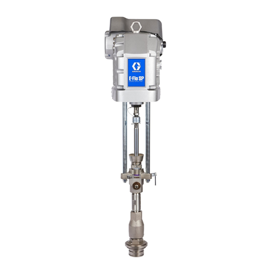
Instructions - Parts
Electric Pumps for
Sealants and Adhesives
For use with non-heated bulk supply of medium to high viscosity sealant and adhesive
materials. For professional use only.
Not approved for use in explosive atmospheres or hazardous locations.
See page 3 for model information, including maximum pump pressure.
Important Safety Instructions
Read all warnings and instructions in this
manual and in all related manuals before
using this equipment. Save all instructions.
EPC100CS
®
Check-Mate
100 Lower Shown
EPD145CS
Dura-Flo™ 145CS
Lower Shown
3A6001B
EPD145SS
Dura-Flo™ 145SS
Lower Shown
EN
Advertisement
Table of Contents

Related Manuals for Graco Check-Mate 100


Summary of Contents for Graco Check-Mate 100
- Page 1 Instructions - Parts Electric Pumps for Sealants and Adhesives 3A6001B For use with non-heated bulk supply of medium to high viscosity sealant and adhesive materials. For professional use only. Not approved for use in explosive atmospheres or hazardous locations. See page 3 for model information, including maximum pump pressure. Important Safety Instructions Read all warnings and instructions in this manual and in all related manuals before...
-
Page 2: Table Of Contents
Flush the Pump ......11 Graco Standard Warranty ....28 Start and Adjust the Pump . -
Page 3: Models
3rd Digit 4th, 5th & 6th Digit 7th Digit 8th Digit ® EP Electric Pump C Check-Mate 100 100cc Check-Mate C Carbon Steel S Severe Duty 6,000 413.0 41.3 ® 200 200cc Check-Mate S Stainless Steel M MaxLife 3,300 227.5 22.7 250 250cc Check-Mate 2,700 186.1 18.6... -
Page 4: Warnings
Warnings Warnings The following warnings are for the setup, use, grounding, maintenance, and repair of this equipment. The exclama- tion point symbol alerts you to a general warning and the hazard symbols refer to procedure-specific risks. When these symbols appear in the body of this manual or on warning labels, refer back to these Warnings. Product-specific hazard symbols and warnings not covered in this section may appear throughout the body of this manual where applicable. - Page 5 Warnings WARNING FIRE AND EXPLOSION HAZARD Flammable fumes, such as solvent and paint fumes, in work area can ignite or explode. Paint or sol- vent flowing through the equipment can cause static sparking. To help prevent fire and explosion: • Use equipment only in well-ventilated area.
- Page 6 Warnings WARNING TOXIC FLUID OR FUMES HAZARD Toxic fluids or fumes can cause serious injury or death if splashed in the eyes or on skin, inhaled or swallowed. • Read Safety Data Sheet (SDS) to know the specific hazards of the fluids you are using. •...
-
Page 7: Component Identification
Component Identification Component Identification EPC100CS Model Shown . 1: Electric Pumps Component ID Key: Electric Driver Wet Cup Coupling Assembly Disconnect Switch Tie Rods Pressure Knob Displacement Pump Grounding Lug Locknut Fluid Outlet Junction Box Fluid Inlet Outlet Check Valve Pump Bleed Valve 3A6001B... -
Page 8: Installation
Installation Installation NOTE: The grounding lug locknut and washer (L) can be used for additional grounding connections such as in spray applications where a ground cable could be con- nected between the electric driver and a metal bucket when flushing a gun into the bucket. Improper wiring may cause electric shock or other serious injury. - Page 9 Installation 2. Remove the two screws and washers to separate 3. Press the junction box gasket tightly against the the junction box cover and disconnect switch (J) back of the junction box cover to ease installation of from the junction box (M) on the electrical driver. the power cord.
-
Page 10: Install System Accessories
Triggering the gun/valve to relieve pres- sure may not be sufficient. NOTE: If you are using the electric pump with Graco supply systems, refer to Electric Supply Systems for . 7: Tighten Cord Grip Sealants and Adhesives manual 3A5379. -
Page 11: Setup
To avoid fire and explosion, always ground the equip- ment and the waste container. To avoid static spark- Before starting, fill the wet cup (H) 1/3 full with Graco ing and injury from splashing, always flush at the Throat Seal Liquid (TSL) or a compatible solvent. -
Page 12: Start And Adjust The Pump
Start and Adjust the Pump Start and Adjust the Pump 5. Pull the pressure adjustment knob (K) out and turn it clockwise until the pump starts moving. Once the pump is moving, push the knob in to lock it. Keep hands and fingers away from the priming piston 6. - Page 13 Start and Adjust the Pump NOTE: When changing fluid containers with the hose and gun/valve already primed, open the pump bleed valve (G) to help prime the pump and vent air before it enters the hose. Close the valve when all air is elimi- nated.
-
Page 14: Shutdown
Shutdown Shutdown 4. Hold a metal part of the gun valve firmly to the side of a grounded metal pail and trigger the gun/valve to relive pressure. 5. Lock the gun/valve trigger. NOTICE Never leave water or water-based fluid in a carbon To reduce the risk of fluid injection, do not use your steel pump overnight. -
Page 15: Maintenance
If oil is low, reduce the product life. open the fill cap and add Graco Part No. 16W645 ISO 220 silicone-free synthetic EP gear oil. Preventative Maintenance The oil capacity is approximately 1.0 - 1.2 quarts (0.9 -... -
Page 16: Troubleshooting
Troubleshooting Troubleshooting 1. Follow the Pressure Relief Procedure on page 14. 2. Check all possible problems and causes before dis- assembling the pump. Problem Cause Solution Pump fails to operate. Obstructed fluid hose or gun/valve; Open, clear*; use a hose with a larger ID. fluid hose ID is too small. -
Page 17: Parts
Parts Parts Electric Pumps with Check-Mate Lowers NOTE: These parts apply to all Check-Mate electric pump configurations. EPC100CS Shown 105a 16/20 16/20/21 Torque to 50-60 ft-lbs (68-81 N•m). Torque to 124-155 ft-lbs (168-210 N•m). Apply blue pipe sealant. Apply tan lubricant. . - Page 18 Parts Parts List for EPC100xx, 200xx, and 250xx Ref Part Description Quantity DRIVER, non-hazardous location 257360 ROD, tie, nxt to cm lower Table 1† LOWER, pump 108098 WASHER, lock, spring 106166 NUT, mach, hex 15H392 ROD, adapter, extreme 244819 COUPLING, assembly, 145-290 xtreme 197340 COVER, coupler 244820...
- Page 19 Parts Pump Lower Warning Labels 184090 PLATE, warning 184462 PLATE, warning, sst 48b 184151 LABEL, warning 50b 172479 LABEL, safety, warning, multiple --- Not available for individual sale. Not Shown. † Refer to Table 1 below for the part number for each model. ...
- Page 20 Parts Parts List for EPC500xx EPC500CS EPC500CM EPC500SS EPC500SM Ref Part Description Quantity DRIVER, non-hazardous location 257360 ROD, tie, nxt to cm lower Table 1† LOWER, cm 500 severe duty 108098 WASHER, lock, spring 106166 NUT, mach, hex 15H370 ADAPTER, 1 1/4-12 184129 COLLAR, coupling 186925...
-
Page 21: Electric Pumps With Dura-Flo Lowers
Parts Electric Pumps with Dura-Flo Lowers NOTE: These parts apply to all Dura-Flo electric pump configurations. EPD115CS Shown 16/18 105a 16/17/18 20/21 Torque to 50-60 ft-lbs (68-81 N•m). Torque to 124-155 ft-lbs (168-210 N•m). Apply blue pipe sealant. Apply tan lubricant. EPDxxxSS/SM . - Page 22 Parts Parts List for All EPDxxxxx Models Ref Part Description Quantity DRIVER, non-hazardous location 257150 ROD, tie, 14 1/4 long 15H562 ROD, tie Table 2† LOWER, xtreme, 115, nf, xseal 101712 NUT, lock 15H392 ROD, adapter xtreme 15H370 ADAPTER, 1 1/4-12 15H371 ADAPTER, m38 x 2 247167...
- Page 23 Parts Ref Part Description Quantity 158586 FITTING, bushing 131523 BUSHING, hex hd, 3/4 npt X 1 npt, ss 101496 BUSHING, pipe 504174 BUSHING, pipe 131519 PLUG, pipe, 3/4 npt, cs 131520 PLUG, pipe, 3/4 npt, ss 17B507 COVER, junction box 115264 SCREW, cap, socket head 104572...
-
Page 24: Dimensions
Dimensions Dimensions EPC100CS Shown . 16: Electric Pump Dimensions Pump Description in. (mm) in. (mm) in. (mm) in. (mm) in. (mm) 100cc Check-Mate - All 38.1 968.6 56.4 1,433.5 200cc Check-Mate - All 39.2 996.3 57.5 1,461.1 250cc Check-Mate - All 39.2 995.6 57.5 1,460.4... -
Page 25: Electric Driver Mounting Hole Pattern
Dimensions Electric Driver Mounting Hole Pattern . 17: Mounting Holes 6.186 in. (157 mm) 6.186 in. (157 mm) Four 3/8-16 Mounting Holes Six 5/8-11 Tie Rod Holes: • 8 in. (203 mm) x 120° bolt circle • 5.9 in. (150 mm) x 120° bolt circle 3A6001B... -
Page 26: Technical Specifications
290cc Dura-Flo - CS 174 lbs 78.9 kg 290cc Dura-Flo - SS 191 lbs 86.6 kg 430cc Dura-Flo - All 195 lbs 88.5 kg Motor Oil Specification Graco part no. 16W645, ISO220 silicone-free synthetic EP gear oil* Capacity 1.5 quarts 1.4 liters 3A6001B... - Page 27 2 in. NPT, female 115CS, 145CS, 180CS, 220CS, 290CS 1 1/4 in. NPT, male Fluid Outlet Sizes - all pump materials Check-Mate 100, 200, 250 1 in. NPT, female Check-Mate 500 1 1/2 in. NPT, female Dura-Flow 115, 145, 180, 220, 290 1 in.
-
Page 28: Graco Standard Warranty
With the exception of any special, extended, or limited warranty published by Graco, Graco will, for a period of twelve months from the date of sale, repair or replace any part of the equipment determined by Graco to be defective.