Table of Contents
Advertisement
Quick Links
Instruction Manual - Parts and Repair
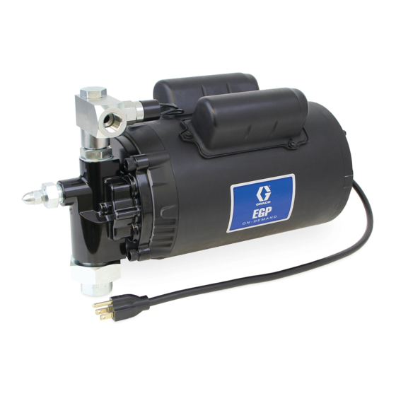
115 VAC EGP
On-Demand Pump
For pumping non-flammable fluids, including motor oils, hydraulic fluid, and antifreeze. Do
not use to pump water. For professional use only.
Not approved for use in explosive atmospheres or hazardous (classified) locations.
25T817 Electric Gear Pump
3.7 gpm (14.0 lpm)
500 psi (3.45 MPa, 34.5 bar) Maximum Working Pressure
Important Safety Instructions
Read all warnings and instructions in this
manual before using the equipment.
Save these instructions.
3A8570B
EN
Advertisement
Table of Contents

Related Manuals for Graco EGP 25T817


Summary of Contents for Graco EGP 25T817
- Page 1 Instruction Manual - Parts and Repair 115 VAC EGP On-Demand Pump 3A8570B For pumping non-flammable fluids, including motor oils, hydraulic fluid, and antifreeze. Do not use to pump water. For professional use only. Not approved for use in explosive atmospheres or hazardous (classified) locations. 25T817 Electric Gear Pump 3.7 gpm (14.0 lpm) 500 psi (3.45 MPa, 34.5 bar) Maximum Working Pressure...
-
Page 2: Table Of Contents
California Proposition 65 ....31 Graco Standard Warranty ....32... -
Page 3: Warnings
Warnings Warnings The following warnings are for the setup, use, grounding, maintenance, and repair of this equipment. The exclamation point symbol alerts you to a general warning and the hazard symbols refer to procedure-specific risks. When these symbols appear in the body of this manual or on warning labels, refer back to these Warnings. Product-specific hazard symbols and warnings not covered in this section may appear throughout the body of this manual where applicable. - Page 4 Warnings WARNING EQUIPMENT MISUSE HAZARD Misuse can cause death or serious injury. • Do not operate the unit when fatigued or under the influence of drugs or alcohol. • Do not exceed the maximum working pressure or temperature rating of the lowest rated system component.
-
Page 5: Typical Installation
. 3 are only guides for selecting and installing system components. Contact your local Graco Distributor for assistance with planning a system to suit your needs. NOTE: The output line fluid pressure should not exceed 400 psi (2.76 MPa, 27.6 bar) while pumping the fluid. - Page 6 Typical Installation . 2: Typical Installation - Option 2: Pump with Hose Reel . 3: Typical Installation - Option 3: Pump with More Than One Hose Reel 3A8570B...
-
Page 7: Component Identification
Typical Installation Component Identification Key: Motor with built in relay Power cord Pressure switch Pressure relief valve Outlet check valve Inlet check with thermal relief Outlet 1/2 npt Pump Power Switch 3A8570B... -
Page 8: Pump Internal Wiring
Typical Installation Pump Internal Wiring 3A8570B... -
Page 9: Installation
115 VAC Graco recommends using 1/2 in. ID hose to keep the The 115 VAC models come wired with a short power working pressure low while the dispense valve is being cord and a grounding electrical plug. -
Page 10: Priming
Installation Priming Pressure Relief Procedure 1. Attach a priming hose to the outlet of the pump. Follow the Pressure Relief Procedure whenever Insert the opposite end of the hose into the tank you see this symbol. through the fill opening. 2. -
Page 11: Operation
Operation Operation Pressure Switch NOTE: When the system is not in use, always turn the power switch (K), (Component Identification, page 7) located on the back of the motor, off. Failure to do so The pressure switch (C) (Component Identification, can result in a spill if a hose ruptures or a leak occurs in page 7) is factory set to 470 psi (3.24 MPa, 32.4 bar). -
Page 12: Recycling And Disposal
Recycling and Disposal Recycling and Disposal End of Product Life At the end of the product’s useful life, dismantle and recycle it in a responsible manner. • Perform the Pressure Relief Procedure. • Drain and dispose of fluids according to applicable regulations. -
Page 13: Troubleshooting
Troubleshooting Troubleshooting 1. Follow Pressure Relief Procedure, page 10, before checking or repairing the equipment. 2. Check all possible problems and causes before disassembling the equipment. Problem Cause Solution Motor is running, but the pump The pump lost the prime. Refer to Priming, page 10. - Page 14 Troubleshooting Problem Cause Solution Remove the inlet suction screen using a The unit pumps, but the output The inlet suction screen is clogged (used flow is low. oil). 3/4 in. (19 mm) hex wrench. Clean or replace the inlet suction screen. There is an air leak in the suction tube.
-
Page 15: Repair
Repair Repair 7. Remove the suction filter (13) using a 3/4 in. (19 mm) hex wrench from the pump inlet (F . 9). Refer to Parts, on page 26 for the numbers in this section. Replace/Clean Suction Screen P/N 133377 Disassembly 1. -
Page 16: Outlet Assembly Kit P/N 133378
Repair Outlet Assembly Kit P/N 133378 11. Pull the pressure switch wire out of the terminal box through the strain relief (F . 11). Disassembly 1. Follow Pressure Relief Procedure. page 10. 2. Turn off and disconnect the power to the pump. 3. -
Page 17: Pump Housing Assembly P/N 133373
Repair 2. Push the pressure switch wire into the wire clamp and into the terminal box through the strain relief . 12 and F . 13). 3. Twist the strain relief nut on using a wrench until tightened (F . 13). 4. - Page 18 Repair 12. Pull the pressure switch wire out of the wire clamp . 17). 13. Remove the four Allen screws (6) using an 5/16 in. (8 mm) hex wrench (F . 17). Wire Clamp terminal Box Cover Screws . 15 6.
- Page 19 Repair Reassembly 1. Put the pump housing assembly onto the motor. The motor shaft key should match the slot on the gear on the inside cover. The pump outlet should face up and the terminal box should be centered between the pump outlet and the pump inlet (F 19 and F .
-
Page 20: Clean And Inspect Pump Gears
Repair Clean and Inspect Pump Gears 11. Pull the pressure switch wire out of the terminal box through the strain relief (F . 23). Disassembly 1. Follow Pressure Relief Procedure. page 10. 2. Turn off and disconnect the power to the pump. 3. - Page 21 Repair wear, replace the pump housing assembly. If neither is present, clean the pump cavity and gears (3) (F . 27). Motor Pump Housing Assembly . 25 . 27 15. Remove four screws (10) on the adapter plate (2) Reassembly using a 1/2 in.
- Page 22 Repair 5. Put the pump housing assembly onto the motor. The motor shaft key should match the slot on the gear on the inside cover. The pump outlet should face up and the terminal box should be centered between the pump outlet and the pump inlet (F 31 and F .
-
Page 23: Clean And Inspect Pressure Relief Valve Assembly
Repair Clean and Inspect Pressure Relief Valve Assembly Disassembly 1. Follow Pressure Relief Procedure. page 10. 2. Turn off and disconnect the power to the pump. 3. Remove the pump from the tank. 4. Remove the suction tube from the pump. 5. -
Page 24: Pump Outlet Check Valve Replacement With Thermal Relief P/N 133097
Repair Reassembly 1. Place the relief ball (7) i into position in the pump housing (see F . 34). 2. Replace the spring guide (8) (see F . 34). 3. Replace the spring (9) (F . 34). 4. Tighten the relief valve housing into the pump housing (F . - Page 25 Notes Notes 3A8570B...
-
Page 26: Parts
Parts Parts Torque value 20 ft.-lb (27.1 N•m) Torque value 30 ft.-lb (40.7 N•m) 3A8570B... - Page 27 Parts Parts Ref. Part No. Description Qty. Pump body ❖ Adapter, pump motor ❖ Gear, pump ❖ Seal, shaft ❖ O-ring ❖ Screw, 3/8 - 16 socket head, cap ❖ Ball, relief valve ❖ Guide, spring ❖ Spring, relief valve ❖...
-
Page 28: Kits And Accessories
Kits and Accessories Kits and Accessories Part Number Description 260124 Suction tube with inlet check assembly 133373 Pump housing assembly 115 V On-Demand Pump 133377 Suction filter 133375 Suction kit 3A8570B... -
Page 29: Pump Performance Chart
Kits and Accessories Part Number Description 133378 Outlet assembly kit 115 VAC On-Demand Pump 133097 Outlet check valve with built-in thermal relief Pump Performance Chart 3A8570B... -
Page 30: Dimensions
Dimensions Dimensions Length (A) Height (B) Width (C) Models Inches Inches Inches 25T817 16.7 421.2 9.67 245.6 226.1 3A8570B... -
Page 31: Technical Specifications
Technical Specifications Technical Specifications 115 VAC Electric Gear On-Demand Pump Metric Maximum working pressure 500 psi 3.45 MPa, 34.5 bar Automatic Relief Setting 500 psi 3.45 MPa, 34.5 bar Pressure Switch Setting 470 psi 3.24 MPa, 32.4 bar Output Flow at 0 psi (0 MPa, 0 bar), 3.7 gpm 14.0 L/min see Pump Performance Chart, page 29... -
Page 32: Graco Standard Warranty
With the exception of any special, extended, or limited warranty published by Graco, Graco will, for a period of twelve months from the date of sale, repair or replace any part of the equipment determined by Graco to be defective.