Table of Contents
Advertisement
Quick Links
Instruction Manual
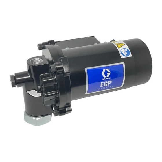
12 VDC EGP
Oil Transfer Pump
For pumping non-flammable fluids, including motor oils, hydraulic fluid, and antifreeze. Do
not use to pump water. For professional use only.
25T819 Electric Gear Pump
3.8 gpm (14.4 lpm)
65 psi (0.45 MPa, 4.5 bar) Maximum Working Pressure
Important Safety Instructions
Read all warnings and instructions in this
manual before using the equipment. Save
these instructions.
3A8569A
EN
Advertisement
Table of Contents

Related Manuals for Graco 12 VDC EGP


Summary of Contents for Graco 12 VDC EGP
- Page 1 Instruction Manual 12 VDC EGP Oil Transfer Pump 3A8569A For pumping non-flammable fluids, including motor oils, hydraulic fluid, and antifreeze. Do not use to pump water. For professional use only. 25T819 Electric Gear Pump 3.8 gpm (14.4 lpm) 65 psi (0.45 MPa, 4.5 bar) Maximum Working Pressure...
-
Page 2: Table Of Contents
California Proposition 65 ....19 Graco Standard Warranty ....20... -
Page 3: Warnings
Warnings Warnings The following warnings are for the setup, use, grounding, maintenance, and repair of this equipment. The exclamation point symbol alerts you to a general warning and the hazard symbols refer to procedure-specific risks. When these symbols appear in the body of this manual or on warning labels, refer back to these Warnings. Product-specific hazard symbols and warnings not covered in this section may appear throughout the body of this manual where applicable. - Page 4 Warnings WARNING PRESSURIZED EQUIPMENT HAZARD Fluid from the equipment, leaks, or ruptured components can splash in the eyes or on skin and cause serious injury. • Follow the Pressure Relief Procedure when you stop spraying/dispensing and before cleaning, checking, or servicing equipment. •...
-
Page 5: Typical Installation
Typical Installation Typical Installation . 1: Typical Installation 3A8569A... -
Page 6: Installation
Installation Installation Grounding then tighten the swivel nut (23) to the bung adapter (14). Mount Hose and Nozzle The equipment must be grounded to reduce the risk of static sparking. Static sparking can cause fumes to 1. Before connecting the hose to the pump, pour 8 z. ignite or explode. -
Page 7: Operation
Operation Operation Pressure Relief Procedure Pump Start Up 1. Check that the ball valve is in the off position. Follow the Pressure Relief Procedure whenever you see this symbol. 2. Turn the power switch, located on the terminal box, to the ON position to start the pump. NOTE: The pump has an internal bypass valve (Pressure Relief Valve) that opens when the pump discharge pressure exceeds 65 psi. -
Page 8: Recycling And Disposal
Recycling and Disposal Recycling and Disposal End of Product Life At the end of the product’s useful life, dismantle and recycle it in a responsible manner. • Perform the Pressure Relief Procedure. • Drain and dispose of fluids according to applicable regulations. -
Page 9: Troubleshooting
Troubleshooting Troubleshooting 1. Follow Pressure Relief Procedure, page 7, before checking or repairing the equipment. 2. Check all possible problems and causes before disassembling the equipment. Problem Cause Solution Motor is running, but the pump There is dirt under the pressure relief Remove the pressure relief valve and will not prime. - Page 10 Troubleshooting Problem Cause Solution The unit pumps, but the output The inlet suction screen is clogged (used Remove the inlet suction screen flow is low. oil). using a 3/4 in. (19 mm) hex wrench. Clean or replace the inlet suction screen.
- Page 11 Troubleshooting Problem Cause Solution The switch does not turn the The fuse or circuit breaker is blown. Check the electrical supply. pump on. There is an electrical problem. Check that proper supply voltage is getting to the pump. There is a defective switch. Replace with a new pump.
-
Page 12: Parts
Parts Parts Torque value 20 ft.-lb (27.1 N•m) Torque value 30 ft.-lb (40.7 N•m) 3A8569A... - Page 13 Parts Ref. Part No. Description Qty. 1 Pump body 2 Adapter, pump motor 3 Gear, pump 4 Seal, shaft 5 O-ring 6 Screw, 3/8 - 16 socket head, cap 7 Ball, relief valve 8 Pin, dowel, steel 3/8 x 3/4 Motor, 12 VDC 10...
-
Page 14: Kits And Accessories
Kits and Accessories Kits and Accessories Part Number Description 133412 Wall mounting kit 260238 Y strainer 260124 Suction tube with inlet check assembly 133376 Dispense kit 3A8569A... - Page 15 Kits and Accessories Part Number Description 133372 Pump housing assembly 230/115 V Transfer Pump 133377 Suction filter 133375 Suction kit 3A8569A...
-
Page 16: Pump Performance Chart
Pump Performance Chart Pump Performance Chart 3A8569A... -
Page 17: Dimensions
Dimensions Dimensions Length (A) Height (B) Width (C) Models Inches Inches Inches 25T819 12.5 317.5 165.1 6.75 171.4 3A8569A... -
Page 18: Technical Specifications
Technical Specifications Technical Specifications 12 VDC Electric Gear Pump Metric Maximum working pressure 65 psi 0.45 MPa, 4.5 bar Automatic Relief Setting 65 psi 0.45 MPa, 4.5 bar Output Flow at 0 psi (0 MPa, 0 bar), 3.8 gpm 14.4 L/min see Pump Performance Chart, page 16 Dimensions... -
Page 19: California Proposition 65
California Proposition 65 California Proposition 65 CALIFORNIA RESIDENTS WARNING: Cancer and reproductive harm – www.P65warnings.ca.gov. 3A8569A... -
Page 20: Graco Standard Warranty
With the exception of any special, extended, or limited warranty published by Graco, Graco will, for a period of twelve months from the date of sale, repair or replace any part of the equipment determined by Graco to be defective.