Endress+Hauser cerabar S Operating Instructions Manual
Pressure transmitter for use in nuclear power plants
Hide thumbs
Also See for cerabar S:
- Operating instructions manual (172 pages) ,
- Operating instructions manual (153 pages) ,
- Operating instructions manual (56 pages)

Related Manuals for Endress+Hauser cerabar S


Summary of Contents for Endress+Hauser cerabar S
- Page 1 BA 234P/00/en/05.07 cerabar S PMP 71 K Software version 7.1 71036531 Pressure Transmitter for use in Nuclear Power Plants Operating Instructions Endress Hauser The Power of Know How...
- Page 2 Short Operating Instructions Cerabar S Short Operating Instructions Remote operation Local operation via Commuwin II Cerabar S without/with display Local operation via keys – – Chapter 3.1 MR = measuring range Level set MR Pressure = required MR? or pressure?
-
Page 3: Table Of Contents
Cerabar S Table of Contents Table of Contents Introduction ... Diagnosis and Trouble-Shooting . . . Diagnosis of errors and warnings . . 37 Measuring system .. - Page 4 Notes on Safety Approved usage The Cerabar S is a pressure transmitter used for measuring gauge or absolute pressure depending on the version. You can display the measured pressure value as a level value using the Commuwin II operating and display program or using the handheld operating terminals for HART.
- Page 5 Cerabar S Notes on Safety Safety Conventions and Symbols In order to highlight safety-relevant or alternative operating procedures in the manual, the following conventions have been used, each indicated by a corresponding icon in the margin. Notes on safety Symbol...
-
Page 6: Introduction
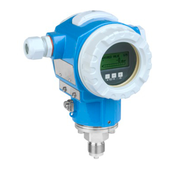
1 Introduction Cerabar S 1 Introduction Applications The Cerabar S pressure transmitter measures the pressure of gases, steam/vapour and liquids and can be used in all areas of chemical and process engineering. ENDRESS+HAUSER CERABAR S Order Code: PMP71K-xxxxxxxxxx Ser.-No.: xxxxxxxxxxx IP 65 p 0…10 bar... -
Page 7: Measuring System
Cerabar S 1 Introduction 1.1 Measuring system The complete measuring system consists of • Cerabar S pressure transmitter with 4…20 mA signal output • optional four-character pressure display • power supply 11.5…45 V DC 4…20 mA Cerabar S with display 0 - 10 bar 11.5…45 V DC... -
Page 8: Installation
2.1 Mounting instructions PMP 71 K The Cerabar S is mounted in the same way as a manometer (DIN EN 839-2). The use of shut-off valves and pigtails is recommended. Its position depends upon the application. •... - Page 9 The PMP 71 K with metallic sensor is available in the following version: Mounting the PMP 71 K • with adapter (welded in) and internal diaphragm. Note! The diaphragm of the Cerabar S must not be pressed in or cleaned with pointed or hard objects. Note! Welded Welded adapter –...
-
Page 10: Mounting Accessories
2 Installation Cerabar S 2.2 Mounting accessories Wall and pipe mounting with accessories 0 - 10 bar Conversion factors 1 mm = 0.039 in 1 in = 25.4 mm Figure 2.6 Dimensions are in mm. Mounted with bracket on a wall 0 - 10 bar ø60.3... -
Page 11: Mounting Position
Cerabar S 2 Installation 2.3 Mounting position After the Cerabar S has been mounted, the housing can be positioned so that: Positioning the housing • the terminal connection compartment can be accessed easily, • the display can be seen optimally, •... -
Page 12: Electrical Connection
2 Installation Cerabar S 2.4 Electrical connection Screened twisted pairs are recommended for the instrumentation cable. Supply voltage: 11.5…45 V DC Internal protection circuits protect against reverse polarity, HF interference and overvoltage peaks. A test signal can be measured using Terminals 1 and 3 without interrupting the process measurement. - Page 13 Connecting the RS 232 C serial interface of a personal computer. This enables the transmitter to be Commubox FXA 191 for remotely operated with the Endress+Hauser Commuwin II operating program. operating via Commuwin II The Commubox FXA191 is used for intrinsically safe signal circuits.
-
Page 14: Operation
The key functions are listed in the table below. Display module Display in measurement mode Figure 3.1 User interface of the Cerabar S, with optional display module -0.1...0.3 bar – – Display in measurement mode 4-figure display of... -
Page 15: Operation Using The Universal Hart Communicator Dxr 275
Cerabar S 3 Operation 3.2 Operation using the Universal HART Communicator DXR 275 PMC 631: LIC0001 LC display Online PMC 631:LIC0001 Online with menu text 1->Group Select 1 >Group Select 2 PV 20 mbar 2 PV 20 mbar HELP Function keys... -
Page 16: Operation With Commuwin
The appropriate server (e.g. HART or ZA 672) must therefore be activated. A description of the operating program Commuwin II is to be found in Operating Instructions BA 124F. Matrix mode You can access the extended functions of the Cerabar S, such as level measurement, (Menu Device) using the "Device/Parameter Matrix" menu. -
Page 17: Local Operation
Cerabar S 4 Local Operation 4 Local Operation 4.1 Commissioning the measuring point This Chapter contains the following information: Contents • General description of operation with keys – Setting lower and upper range-values: calibration without reference pressure – Adjusting lower and upper range-values: adjustment with reference pressure –... - Page 18 4 Local Operation Cerabar S Lower and upper On devices without a display, you can set the lower and upper-range values with the range-values: reference pressure and an ammeter. The reference pressure should be near the lower setting using reference and upper range-values.
-
Page 19: Damping Τ
Fixed damping values are assigned to the switch positions 0…7. They can be adjusted directly on the instrument. (Fixed damping values for root functions are assigned to the switch positions 8…F. This function cannot be selected for the Cerabar S.) Damping-linear function: switch positions 0…7 100 % 63 % τ... -
Page 20: Pressure Measurement
5 Pressure Measurement Cerabar S 5 Pressure Measurement 5.1 Start-up with the Universal HART Communicator DXR 275 or Commuwin II Contents This Chapter contains the following information: • Preparatory work for start-up – Resetting to factory settings – Setting damping –... - Page 21 Cerabar S 5 Pressure Measurement Damping τ The damping affects the speed with which the display in V0H0 and the output signal react to changes in pressure. Setting the damping by remote communication is only possible with switch position "0"...
- Page 22 5 Pressure Measurement Cerabar S Lower and upper The required pressure for lower and upper range-value is set by remote communication. range-values: calibration without reference pressure Matrix Path through the Entry menus Main group: Basic settings Enter known pressure for lower range-value...
- Page 23 Cerabar S 5 Pressure Measurement The "Zero Correction" (V9H5) parameter offers a further possibility of carrying out position Zero correction calibration. Besides the display value, and in contrast to position calibration using bias pressure (V0H5/V0H6), the current value is balanced with the on-site display (measured value (V0H0)).
-
Page 24: Locking/Unlocking Operation
5 Pressure Measurement Cerabar S Alarm mode To indicate an error, an error code is transmitted with the measured value. The bar graph in the display adopts the value selected by the operator. For the "Alarm mode" (V0H8) = "Max. alarm" setting, the current is adjustable from 21…22.5 mA using the "Max. -
Page 25: Measuring Point Information
Cerabar S 5 Pressure Measurement 5.3 Measuring point information The following information on the measuring point can be retrieved: Matrix field Display or entry Measured values V0H0 Main measured value: pressure V2H6 Sensor temperature (units in V7H9 selectable) V7H0 Output current in mA... -
Page 26: Level Measurement
6 Level Measurement Cerabar S 6 Level Measurement 6.1 Start-up with the Universal HART Communicator DXR 275 or Commuwin II Function check The "Level linear", "Level cylindrical horizontal" and "Level manual" modes are selectable via communication. In these modes, the current measured pressure value is automatically converted to "%". - Page 27 Cerabar S 6 Level Measurement Resetting to factory By entering a code, the entries in the matrix Matrix Path through Entry settings the menus are reset partially or completely to factory settings. Further information on the various Main group: Transmitter information...
- Page 28 6 Level Measurement Cerabar S Selecting unit for level, The units for level, volume or weight are selectable using the "Unit After Linearisation" volume or weight (Unit (V3H3) parameter. Selecting a unit only helps to improve the display and does not affect after linearisation) the main measured value in the matrix field V0H0.
- Page 29 Cerabar S 6 Level Measurement If calibration is carried out with water, or if the product changes, the calibration can be Density correction simply corrected by entering a density factor. new density density factor = effective factor • –––––––––––– old density Example: A vessel is filled with water and then calibrated.
-
Page 30: Calibration With Reference Pressure
Empty Calibration point "empty" at the horizontal Confirm 0 hl same height as the mounting Enter the level or volume at the minimum level point for the Cerabar S BA187Y53 V3H1 Display at e.g. 0 4 mA Confirm Enter the level or volume at the maximum level... -
Page 31: Dry Calibration
Dry calibration is a theoretical calibration which can be carried out even though the Cerabar S is not mounted and with a vessel filled to any height. The "empty" calibration point is usually at the mounting point of the measuring cell. If measurement starts at another level, then this must be included in the calculation. -
Page 32: Linearisation
With semi-automatic entry of the linearisation curve the tank is linearisation curve filled or emptied. The height is automatically determined by the "gauging" Cerabar S by the hydrostatic pressure, the appropriate volume is entered. In addition V3H6 offers the functions: Activating table A linearisation table is valid only if it is specifically activated. - Page 33 Cerabar S 6 Level Measurement Manual entry Requirements for manual linearisation are Entering the pairs of values for the as follows: linearisation curve is done after a calibration with reference pressure or a dry • The max. 21 pairs of values for the calibration in %.
- Page 34 6 Level Measurement Cerabar S Semi-automatic entry Requirements for semi-automatic entry of Entering the pairs of values for the the linearisation curve are as follows: linearisation curve is done after a calibration with reference pressure or a dry • The vessel can be filled for e.g. empty/full calibration in %.
-
Page 35: Locking/Unlocking Operation
Cerabar S 6 Level Measurement The current signal range is set to 3.8…20.5 mA as standard when operating correctly. When 4 mA level selecting the 4 mA level, a minimum current signal is not to fall below 4 mA. Thus: •... -
Page 36: Measuring Point Information
6 Level Measurement Cerabar S 6.6 Measuring point information The following information on the measuring point can be retrieved: Matrix field Display or entry Measured values V0H0 Main measured value: level, volume or weight V2H6 Sensor temperature (units in V7H9 selectable) -
Page 37: Diagnosis And Trouble-Shooting
When the Cerabar S detects a warning: Warnings • An error code is transmitted along with the measured value: the Cerabar S continues measuring • The actual error code can be read in V2H0, the last error code in V2H1. - Page 38 7 Diagnosis and Trouble-Shooting Cerabar S Code Type Cause and Remedy Priority E 115 Error Sensor overpressure – Overpressure present. Reduce pressure until message disappears. – Cable connection between sensor and main electronics interrupted. Check cable connection. – Sensor defective. Replace sensor.
-
Page 39: Current Simulation
V2H9 Default values e.g. 2380 The Cerabar S differentiates among different types of reset each with various responses. To find out which parameters are reset with the 5140, 2380 and 731 reset codes, refer to the table on page 40. - Page 40 7 Diagnosis and Trouble-Shooting Cerabar S Reset Codes V0 Measured Set 4 mA Set 20 mA 4 mA 20 mA Bias Set output Alarm Select value value value value value bias pressure damp. mode pressure autom. autom. pressure autom. unit...
-
Page 41: Editing Limits
Cerabar S 7 Diagnosis and Trouble-Shooting 7.4 Editing limits To avoid incorrect device functioning because of excessively large or excessively small values, for some parameters there is a minimum and maximum permissible input value (editing limits). The set measuring range must be within these editing limits. An attempt to exceed or undershoot these editing limits generates an error message (refer to Chapter 7.1 Diagnosis of errors and warnings). - Page 42 7 Diagnosis and Trouble-Shooting Cerabar S Example of editing limits for pressure sensor Maximum measuring range 0…10 bar Set span = 8 bar 10% of 10% of "High "High Set span = 8 bar Sensor Sensor Limit" Limit" Pressure sensor: 0 bar…10 bar...
-
Page 43: Maintenance And Repair
Cerabar S 8 Maintenance and Repair 8 Maintenance and Repair 8.1 Repair If the Cerabar S must be sent to Endress+Hauser for repair, then a note should be enclosed containing the following information. • An exact description of the application •... -
Page 44: Mounting The Display
8 Maintenance and Repair Cerabar S 8.2 Mounting the display BA187Y58 • Mounting the display Switch off power supply. • Open the cover to the display compartment (use a cover with a sight glass after mounting the display). 4. ..2... -
Page 45: Exchanging The Sensor Module And Electronics
Screw in the sensor module right to the stop, taking care to turn the cable with it. • To ensure that the Cerabar S can be fully turned when mounted, turn the unit in the other direction by one complete turn. -
Page 46: Recalibration
8 Maintenance and Repair Cerabar S 8.4 Recalibration If you want to fit the pressure transmitter with a diaphragm seal you can recalibrate the sensor using the "Low Sensor Trim" (V7H4) and "High Sensor Trim" (V7H5) parameters. The highest measurement accuracy is obtained when the value for the "Low Sensor Trim"... -
Page 47: Replacement Parts
8 Maintenance and Repair 8.5 Replacement parts The diagram on the next page shows all replacement parts needed for Cerabar S, together with their order numbers, which can be ordered from Endress+Hauser. When ordering replacement parts, please note the following: •... -
Page 48: Technical Data
Cerabar S 9 Technical Data General information Manufacturer Endress+Hauser Instrument Pressure transmitter Designation Cerabar S PMP 71 K Technical documentation BA 234P/00/en Version 05.07 Technical data DIN 19259 Application Measurement of absolute and gauge pressure in gases, vapours and liquids... - Page 49 Cerabar S 9 Technical Data ≥ 21.5 mA Output Output signal Standard: Options: max.: settling in the range 21…22.5 mA (Continuation) continue: last measured value held min.: 3.6 mA Resolution 1µA Damping (Integration time) adjustable, 0…16 s via rotary switch...
- Page 50 9 Technical Data Cerabar S Accuracy Loca (Loss of Coolant Non-recurring permitted accident load, see temperature and pressure Accident) diagram. Deviation of <0.2% after influence has subsided (see diagram). (Continuation) ϑ [°C (°F)] 100 (212) 90 (194) 80 (176) 70 (158)
- Page 51 Ripple No effect for 4…20 mA signal up to ±5% residual ripple within permissible range Certificates and Approvals CE Mark By attaching the CE Mark, Endress+Hauser confirms that the instrument fulfils all the requirements of the relevant EC directives. Endress+Hauser...
- Page 52 Version- x Cal./Adj. TAG # without display Dat./Insp.: 0 - 10 bar 27 AF Figure 9.1 Dimensions Cerabar S PMP 71 K ENDRESS+HAUSER CERABAR S Order Code: PMP71K-xxxxxxxxxx Ser.-No.: xxxxxxxxxxx IP 65 p 0…10 bar Pmax 26.7 bar KTA 3505 U 45 VDC Span 0.011/10 bar...
-
Page 53: Operating Matrix
Cerabar S 10 Operating Matrix 10 Operating Matrix 10.1 Matrix Commuwin II (Software version 7.1) Measured Set 4 mA Set 20 mA 4 mA value 20 mA Set bias Bias Set output Alarm Select value value value automatic value pressure... -
Page 54: Matrix Universal Hart Communicator
10 Operating Matrix Cerabar S 10.2 Matrix Universal HART Communicator DXR 275 (Software version 7.1) Group Select 1 (H0) 2 (H1) 3 (H2) 4 (H3) 5 (H4) 6 (H5) 7 (H6) 8 (H7) 9 (H8) 10 (H9) Bias Basic Measured... -
Page 55: Description Of Parameters
Cerabar S 10 Operating Matrix 10.4 Description of parameters Parameter Description Measured Value This parameter indicates the current value measured. The matrix field V0H0 (V0H0) corresponds to the on-site display. For the "Pressure" operating mode, select a pressure unit using the parameter "Select Pressure Unit" (V0H9). The measured value is converted and displayed in the pressure unit you selected. - Page 56 Indicates the device and software number. (continuation) (V2H2) The first two digits represent the device number and digits 3 and 4 the software version. Cerabar S HART with SW 7.1 = 6571 Peak Hold P Min Indicates the smallest measured pressure value (maximum pointer). (V2H3) This parameter is reset to the current pressure value when you confirm by pressing the ENTER key.
- Page 57 Cerabar S 10 Operating Matrix Description of Parameter Description parameters Unit after Only for operation modes "Pressure%", "Level linear", "Level cylindrical horizontal", (continuation) Linearisation "Level curve" and "Square root" (flow) (V3H3) Selects a level, volume or weight unit. The options depend on the selected operation mode.
- Page 58 10 Operating Matrix Cerabar S Description of Parameter Description parameters High Sensor Enter the upper point of the sensor characteristic curve for sensor calibration. (continuation) Trim Use this parameter to assign a new value to a reference pressure applied to the device.
- Page 59 Cerabar S 10 Operating Matrix Description of Parameter Description parameters Serial No. Sensor Indicates the serial number of the sensor. (continuation) (VAH3) Process Select and display the process connection material on the plus side. Connection P+ Options: steel, 304 stainless, 316 stainless, Hastelloy C, Monel, tantalum, titanium,...
-
Page 61: Index
... . 55-59 Dimensions Cerabar S ....Position calibration, display only (bias pressure) . . . 18, 22 Display messages for diagnosis . - Page 64 Tel. (0 11) 50 31 34 55, Fax (0 11) 50 31 30 67 Belarus Belorgsintez Poland Philippines Canada Minsk Endress+Hauser Polska Sp. z o.o. Endress+Hauser Ltd. Endress+Hauser Inc. Tel. (01 7) 2 5084 73, Fax (01 7) 2 50 85 83 Wroclaw Pasig City, Metro Manila Burlington, Ontario Tel.