
Related Manuals for Endress+Hauser Stamosens CSM750


Summary of Contents for Endress+Hauser Stamosens CSM750
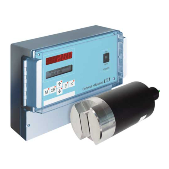
- Page 1 Operating Instructions Stamosens CSM750/CSS70 For measurement of the dissolved organic substances or the spectral absorption coefficient BA305C/07/en/06.05 5150702 Valid as of: Software version 3.7...
- Page 2 You should carry out maintenance work to ensure good performance. Here, you can find the maintenance schedule. Æ Accessories Page 31 Accessories and ordering information Æ Troubleshooting Page 34 System checklist Æ Æ Index Page 44 Use the index to find information quickly. Endress+Hauser...
-
Page 3: Table Of Contents
Stamosens CSM750/CSS70 Table of contents Safety instructions ....4 Technical data ....35 Designated use . -
Page 4: Safety Instructions
Safety instructions Stamosens CSM750/CSS70 Safety instructions Designated use Sensor CSS70 and transmitter CSM750 form an analytical system for continuous measurement of the spectral absorption coefficient. The system is specifically designed to monitor the dissolved organic substances: • in the wastewater effluent stream and •... -
Page 5: Return
Stamosens CSM750/CSS70 Safety instructions Return If the sensor or the transmitter has to be repaired, please return it cleaned to the sales center responsible. Please enclose the completed "Declaration of contamination" (copy the second last page of these Operating Instructions) with the packaging and the transportation documents. -
Page 6: Identification
Identification Stamosens CSM750/CSS70 Identification Device designation 2.1.1 Nameplate Please check the order code from the nameplate with the product structure and with your order. Stamosens CSM750 order code / Best.Nr.: CSM 750-7A1A serial no. / Ser.-Nr.: 610065C3NI1 output 1 / Ausgang 1:... -
Page 7: Scope Of Delivery
Stamosens CSM750/CSS70 Identification Sensor Cleaning unit not selected 230 V 115 V Special version acc. to customer's specification Measuring range 0.3 ... 50 m or 0.4 ... 60 mg/l CSB in reference to KHP 15 ... 700 m or 20 ... 900 mg/l CSB in reference to KHP 2 ... -
Page 8: Installation
Installation Stamosens CSM750/CSS70 Installation Measuring system overview 3.1.1 Immersion A complete measuring system comprises: • Transmitter CSM750 • Sensor CSS70 • An immersion assembly with pendulum frame Optional: • Cleaning unit with compressor • Mounting post and weather protection cover... -
Page 9: Incoming Acceptance, Transport, Storage
Stamosens CSM750/CSS70 Installation 3.1.2 Flow (bypass) POWER M CE a0004451 Fig. 4: Complete measuring system Transmitter CSM750 Outlet Sensor wall bracket Flow assembly Supply of calibration standard/cleaning agent (when Overpressure protection manually calibrating or cleaning) Sensor CSS70 Free outlet Power supply / signal output Incoming acceptance, transport, storage •... -
Page 10: Installation Conditions
Installation Stamosens CSM750/CSS70 Installation conditions 3.3.1 Design, dimensions 241 / 9.49 115 / 4.53 212 / 8.35 60 / 2.36 198 / 7.80 69 / 2.72 198 / 7.80 mm / inch a0000949-en Fig. 5: Transmitter dimensions 360 / 14.17... - Page 11 Stamosens CSM750/CSS70 Installation 214 / 8.43 mm / inch 152 / 5.98 a0003231-en Fig. 7: Compressor of the cleaning unit 3.3.2 Sensor holders " Caution! Do not install the sensor suspended from the cable. Use a wall bracket or an immersion assembly with pendulum frame for sensor mounting.
- Page 12 Installation Stamosens CSM750/CSS70 Ø 40 / 1.57 mm/inch 130/5.12 45° a0000904-en a0000903-en Fig. 9: Immersion assembly for sensor Fig. 10: Pendulum frame for immersion assembly 3.3.3 Weather protection cover and round post mount mm / inch 300 / 11.81 270 / 10.63 mm / inch 150 / 5.91...
- Page 13 Stamosens CSM750/CSS70 Installation 3.3.4 Flow assemblies • Flow assembly for drinking water application, with/without reduction of the dead volume, stainless steel 1.4571 (AISI 316 Ti) / PVDF; 60 / 2.36 mm / inch Ø 6.6 / 0.26 G ¼ a0000946-en Fig.
-
Page 14: Installation
Installation Stamosens CSM750/CSS70 • Flow assembly, – with/without reduction of the dead volume and overpressure protection – PVDF/PVC, without reduction of the dead volume, with stop valves and overpressure protection DN10 G¾ DN10 70 / 2.76 92 / 3.62 88 / 3.46... -
Page 15: Wiring
Stamosens CSM750/CSS70 Wiring Wiring Electrical connection Warning! • The electrical connection must only be carried out by a certified electrician. • Technical personnel must have read and understood the instructions in this manual and must adhere to them. • Ensure that there is no voltage at the power cable before beginning the connection work. -
Page 16: Inputs And Outputs
Wiring Stamosens CSM750/CSS70 Inputs and outputs 4.3.1 Control input (+24 V) Output Terminals Function 24 / 25 Hold function, i.e. measurement is interrupted and the current 24 V DC "INPUT" value in the display is frozen Note! Use U (+24 V, terminal 26) to control the 24 V DC "INPUT". Then connect terminal 27 (0 V) and terminal 24 (0 V). - Page 17 Stamosens CSM750/CSS70 Wiring Warning! Disconnect the device from the power supply before opening it. The connection contacts are live even when the transmitter is switched off. Fuse Transmitter 230V AC / 50Hz 115V AC / 60Hz a0000951-en Fig. 18: Connection of the cleaning unit 4.4.2...
-
Page 18: Serial Interface
Wiring Stamosens CSM750/CSS70 Note! The connection is the same as that of the cleaning unit with integrated compressor. The terminal assignment can be found in the table or illustration in the previous chapter. Serial interface RS 232 of the transmitter... -
Page 19: Operation
Stamosens CSM750/CSS70 Operation Operation Display and operating elements Me as. value 18.0 mg/l -N POWER M CE a0000948-en Fig. 20: Display and operating elements LED (measured value) LC display (status) Operating keys Indicator LEDs Power Supply switch Local operation The operating keys and the integrated indicator LEDs have the following functions:... - Page 20 Operation Stamosens CSM750/CSS70 5.2.1 Main menu Access the main menu by holding down the key until “MEASUREMENT” is displayed. For the main menu options and information about them, please see the following table. Option Display Info • Acquiring and displaying: –...
- Page 21 Stamosens CSM750/CSS70 Operation 5.2.2 MEASUREMENT Note! In the following table and in the tables in the next chapter, example images can be found for each option under "Display". In addition to the numerical values, the parameter is also displayed in some options.
- Page 22 Operation Stamosens CSM750/CSS70 Option Setting range Display Info (factory settings bold) 0 ... 20 mA Selection of the current range, on which the measuring Analog output Analog output 4 ... 20 mA range should be mapped. 4-20 mA Alarm value A...
- Page 23 Stamosens CSM750/CSS70 Operation 5.2.5 CALIBRATION POINTS Option Setting range Display Info (factory settings bold) To access the sub-menu, enter the code "99". 0 ... 99 Code No. Code number If the incorrect code is entered, the program exits to the MEASUREMENT main menu.
- Page 24 Operation Stamosens CSM750/CSS70 5.2.9 DIAGNOSTICS Note! • This menu is a "read-only menu". • You can find the individual error messages, their meaning and solutions to problems in chapter "Troubleshooting instructions". • If at least one error message is displayed for more than 10 s, the signal output is set to "fault".
-
Page 25: Commissioning
Stamosens CSM750/CSS70 Commissioning Commissioning Function check Warning! • Check that all connections are secure. In particular, ensure that all hose connections are secure, so that no leaks occur. • Ensure that the power supply voltage corresponds to the voltage specified on the nameplate! Switch-on 6.2.1... - Page 26 Commissioning Stamosens CSM750/CSS70 Action Display Use the keys to select the configuration for alarm value A and confirm with Repeat the previous step for alarm value B. Alarm B normally open Select the configuration for the diagnostic alarms similar to the alarm value setting.
- Page 27 Stamosens CSM750/CSS70 Commissioning Action Display Press four times and confirm with FREQUENCY Press the key to set the "99" code and confirm with Code No. to set the previously noted frequency associated with the laboratory Frequency measured value. 4836 Hz Press .
- Page 28 Commissioning Stamosens CSM750/CSS70 6.2.3 Five-point calibration When determining the SAC as a correlation to CSB, BSB or TOC, it is not a good idea to use one-point calibration. Therefore, carry out a five-point calibration: Prepare or purchase calibration standards. For example 10, 20, 30 and 40 mg/l DOC (Potassium Hydrogen Phthalate solutions).
-
Page 29: Maintenance
Stamosens CSM750/CSS70 Maintenance Maintenance The measuring system does not contain any wearing parts and generally requires little maintenance. However, you should still carry out the following maintenance work to ensure perfect functionality: • Cleaning the sensor • Calibration • Checking cables and connections "... -
Page 30: Checking Cables And Connections
Maintenance Stamosens CSM750/CSS70 Type of soiling Cleaning agent Light biological coatings Pressurized water or Ultrafiltration cleaner, but never together with acid! " Caution! Do not use halogenated organic solvents and no acetone. These solvents may destroy plastic components of the sensor and are suspected to cause cancer (e.g. chloroform). -
Page 31: Accessories
Stamosens CSM750/CSS70 Accessories Accessories • Weather protection cover CYY101, for field mounting of the transmitter; order no. 50061258 • Round post mount CYY102, for weather protection cover mounting on vertical or horizontal pipes; order no. 50064291 • Immersion assembly, offset 45°... - Page 32 Accessories Stamosens CSM750/CSS70 • Sensor terminal housing, for cable extension from transmitter to sensor; order no. 51502956 110 / 4.33 mm / inch Sensor Pg 11 a0000944-en.eps a0000945-en Fig. 22: Sensor terminal housing Fig. 23: Sensor connection to sensor terminal housing •...
- Page 33 Stamosens CSM750/CSS70 Accessories • Flow vessel, open version; with inlet and outlet order no. 51515762 200 / 7.87 280 / 11.02 40 / 1.57 Ø190 / 7.48 mm / inch a0000943-en Fig. 25: Flow vessel • Flow assembly, without external rinsing unit –...
-
Page 34: Troubleshooting
Troubleshooting Stamosens CSM750/CSS70 Troubleshooting Error messages Error message Error Possible cause Measures frequency Incorrect sensor type - - - - Connected sensor does not correspond to the sensor selected in the • Replace sensor) CONFIGURATION menu • Correct sensor type in the... -
Page 35: Technical Data
Stamosens CSM750/CSS70 Technical data Technical data 10.1 Input Measured variable Spectral absorption coefficient [m Measuring range SAC 0-50 0...50 m or 0...35 mg/l DOC/TOC or 0...80 mg/l CSB/BSB SAC 0-250 0...250 m or 0...150 mg/l DOC/TOC or 0...400 mg/l CSB/BSB SAC 0-700 0...700 m... -
Page 36: Process
Technical data Stamosens CSM750/CSS70 10.6 Process Medium temperature 2 ... 40 °C (36 ... 104 °F) Medium pressure max. 1 bar (14.5 psi) Solid content < 2 g/l 10.7 Mechanical construction Design, dimensions see chapter "Installation" Transmitter approx. 1.6 kg (3.5 lb) -
Page 37: Appendix
Stamosens CSM750/CSS70 Appendix Appendix 11.1 Operating matrix a0001046-en Endress+Hauser... - Page 38 Appendix Stamosens CSM750/CSS70 a0001047-en Endress+Hauser...
-
Page 39: Control For A Customer-Specific Cleaning Unit
Stamosens CSM750/CSS70 Appendix 11.2 Control for a customer-specific cleaning unit CNM 750 max. 250 V AC / 2 A max. 30 V DC / 1 A Terminal Cleaning Solenoid valve 230 V AC 230 V AC a0001048-en Fig. 27: Example 1... - Page 40 Appendix Stamosens CSM750/CSS70 a0001049-en Fig. 28: Example 2 Endress+Hauser...
-
Page 41: Factory Settings
Stamosens CSM750/CSS70 Appendix 11.3 Factory settings 11.3.1 Sensor type SAC 0-50 Parameter Factory setting dependent on the selected measuring unit 1/m SAC mg/l DOC mg/l TOC mg/l BSB mg/l CSB CONFIGURATION Measuring unit 1/m SAC mg/l DOC mg/l TOC mg/l BSB... - Page 42 Appendix Stamosens CSM750/CSS70 11.3.2 Sensor type SAC 0-250 Parameter Factory setting dependent on the selected measuring unit 1/m SAC mg/l DOC mg/l TOC mg/l BSB mg/l CSB CONFIGURATION Measuring unit 1/m SAC mg/l DOC mg/l TOC mg/l BSB mg/l CSB...
- Page 43 Stamosens CSM750/CSS70 Appendix 11.3.3 Sensor type SAC 0-700 Parameter Factory setting dependent on the selected measuring unit 1/m SAC mg/l DOC mg/l TOC mg/l BSB mg/l CSB CONFIGURATION Measuring unit 1/m SAC mg/l DOC mg/l TOC mg/l BSB mg/l CSB...
-
Page 44: Index
Stamosens CSM750/CSS70 Index Accessories........31 Icons Symbols . - Page 45 Stamosens CSM750/CSS70 PARAMETER ENTRY ......22 Performance characteristics ......35 Post-connection check .
- Page 46 Stamosens CSM750/CSS70 Endress+Hauser...
- Page 47 Declaration of Contamination Erklärung zur Kontamination Because of legal regulations and for the safety of our employees and operating equipment, we need the "declaration of contamination", with your signature, before your order can be handled. Please make absolutely sure to include it with the shipping documents, or - even better - attach it to the outside of the packaging.
- Page 48 www.endress.com/worldwide BA305C/07/en/06.05 Printed in Germany / FM+SGML 6.0 / EN 5150702...