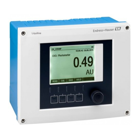
Endress+Hauser Liquiline CM44P Brief Operating Instructions
Universal four-wire multichannel controller for process spectrometers and memosens sensors
Hide thumbs
Also See for Liquiline CM44P:
- Supplementary documentation (75 pages) ,
- Operating instructions manual (204 pages)
Table of Contents
Advertisement
Quick Links
KA01450C/07/EN/02.22-00
71569575
2022-05-31
Products
Brief Operating Instructions
Liquiline CM44P
Universal four-wire multichannel controller for
process spectrometers and Memosens sensors
These instructions are Brief Operating Instructions; they are
not a substitute for the Operating Instructions pertaining to
the device.
Detailed information on the device can be found in the
Operating Instructions and in the other documentation
available at:
• www.endress.com/device-viewer
• Smart phone/tablet: Endress+Hauser Operations App
Solutions
Services
Advertisement
Table of Contents

Related Manuals for Endress+Hauser Liquiline CM44P


Summary of Contents for Endress+Hauser Liquiline CM44P
- Page 1 These instructions are Brief Operating Instructions; they are not a substitute for the Operating Instructions pertaining to the device. Detailed information on the device can be found in the Operating Instructions and in the other documentation available at: • www.endress.com/device-viewer • Smart phone/tablet: Endress+Hauser Operations App...
- Page 2 Liquiline CM44P Order code: XXXXX-XXXXXX Ser. no.: XXXXXXXXXXXX Ext. ord. cd.: XXX.XXXX.XX Serial number www.endress.com/deviceviewer Endress+Hauser Operations App A0040778 Endress+Hauser...
-
Page 3: Table Of Contents
Liquiline CM44P Table of contents Table of contents About this document ............. . 4 Warnings . -
Page 4: About This Document
About this document Liquiline CM44P About this document Warnings Structure of information Meaning This symbol alerts you to a dangerous situation. DANGER Failure to avoid the dangerous situation will result in a fatal or serious injury. Causes (/consequences) If necessary, Consequences of non- compliance (if applicable) ‣... -
Page 5: Symbols On The Device
Documentation The following manuals complement these Brief Operating Instructions and are available on the product pages on the Internet: • Operating Instructions for Liquiline CM44P, BA01954C • Device description • Commissioning • Operation • Software description (excluding sensor menus; these are described in a separate manual - see below) •... -
Page 6: Basic Safety Instructions
Intended use 2.2.1 Non-hazardous atmosphere Liquiline CM44P is a multichannel controller for connecting process spectrometers and digital sensors with Memosens technology in non-hazardous environments. The device is designed for use in the following applications: • Food and beverages •... -
Page 7: Workplace Safety
Liquiline CM44P Basic safety instructions Use of the device for any purpose other than that described, poses a threat to the safety of people and of the entire measuring system and is therefore not permitted. The manufacturer is not liable for damage caused by improper or non-designated use. -
Page 8: Product Safety
Basic safety instructions Liquiline CM44P Product safety 2.5.1 State-of-the-art technology The product is designed to meet state-of-the-art safety requirements, has been tested, and left the factory in a condition in which it is safe to operate. The relevant regulations and international standards have been observed. -
Page 9: Incoming Acceptance And Product Identification
Liquiline CM44P Incoming acceptance and product identification Incoming acceptance and product identification Incoming acceptance Verify that the packaging is undamaged. Notify the supplier of any damage to the packaging. Keep the damaged packaging until the issue has been resolved. -
Page 10: Scope Of Delivery
Click the product overview. A new window opens. Here you fill information pertaining to your device, including the product documentation. 3.2.3 Manufacturer address Endress+Hauser Conducta GmbH+Co. KG Dieselstraße 24 D-70839 Gerlingen Scope of delivery The scope of delivery comprises: •... -
Page 11: Mounting
Liquiline CM44P Mounting Mounting Mounting requirements 4.1.1 Mounting plate 4 x 6.5 (0.26) 80 (3.15) 125 (4.92) A0012426 1 Mounting plate. Engineering unit: mm (in) Endress+Hauser... - Page 12 Mounting Liquiline CM44P 4.1.2 Weather protection cover NOTICE Effect of climatic conditions (rain, snow, direct sunlight etc.) Impaired operation to complete transmitter failure are possible! ‣ Always use the weather protection cover (accessory) when installing the device outdoors. 300 (11.8) 170 (6.69)
- Page 13 Liquiline CM44P Mounting NOTICE Incorrect mounting location in the cabinet, spacing regulations not observed Possible malfunctions as a result of heat buildup and interference from neighboring devices! ‣ Do not position the device directly above sources of heat. The temperature specification must be observed.
- Page 14 Mounting Liquiline CM44P 4.1.4 Wall mounting 205.5 (8.09) 4 x Ø 4.5 (0.18) A0027859 4 Drilling pattern for wall mounting in mm (in) 4.1.5 Mounting the external display The mounting plate also serves as the drilling template. The marks on the side help you mark the position of the drill holes.
-
Page 15: Mounting The Measuring Device (Field Device)
Liquiline CM44P Mounting 4.1.6 Cable length for optional display Length of display cable provided (cabinet device only): 3 m (10 ft) Maximum permitted length of a display cable (cabinet device only): 5 m (16.5 ft) Mounting the measuring device (field device) 4.2.1... - Page 16 Mounting Liquiline CM44P A0033045 A0025885 7 Post mounting 8 Attach the device and click it into place Place the device on the mounting plate. Slide the device downwards in the guide on the mounting rail until it clicks into place.
- Page 17 Liquiline CM44P Mounting A0025886 A0027803 10 Rail mounting 11 Attach the device and click it into place Place the device on the mounting plate. Slide the device downwards in the guide on the mounting rail until it clicks into place.
-
Page 18: Mounting The Measuring Device (Cabinet Device)
Mounting Liquiline CM44P A0027799 A0027797 14 Wall mounting 15 Attach the device and click it into place Place the device on the mounting plate. Slide the device downwards in the guide on the mounting rail until it clicks into place. - Page 19 Liquiline CM44P Mounting Slide the securing clips upwards until they click, thereby securing the device to the DIN rail. Mount the external power unit in the same way. 4.3.2 Wall mounting Mounting material (screws, dowels) are not included in the scope of delivery and must be provided by the customer.
- Page 20 Mounting Liquiline CM44P Mounting the display on the door of the cabinet Hold the mounting plate from the outside against the door of the control cabinet. Choose the point at which you wish to install the display. Make all the markings.
- Page 21 Liquiline CM44P Mounting Pull the display cable through the hole in the middle, and place the display from the outside through the four holes drilled for this purpose, ensuring that the torx screws have been unscrewed to the last half turn but are still in place. Ensure that the rubber frame (seal, highlighted blue) does not become damaged and is properly positioned on the surface of the door.
-
Page 22: Post-Mounting Check
Mounting Liquiline CM44P 16 Mounted display NOTICE Incorrect installation Damage, e.g. to the cable, or malfunctions are possible! ‣ Lay cables in such a way that they do not get squashed e.g. when closing the cabinet door. ‣ Plug the display cable only into the RJ45 socket in the base module. Otherwise, the display will not function. -
Page 23: Electrical Connection
Liquiline CM44P Electrical connection Electrical connection Connecting the measuring device WARNING Device is live! Incorrect connection may result in injury or death! ‣ The electrical connection may be performed only by an electrical technician. ‣ The electrical technician must have read and understood these Operating Instructions and must follow the instructions contained therein. - Page 24 Electrical connection Liquiline CM44P 5.1.2 Cable mounting rail A0048299 19 Cable mounting rail and associated function (field device) Cable mounting rail Cable clamps (fixing and grounding the sensor cables) Threaded bolt (protective ground connection, central grounding point) 5.1.3 Connecting the cable shield The sensor cable, fieldbus cable and Ethernet cable must be shielded cables.
- Page 25 Liquiline CM44P Electrical connection Remove the dummy plug. Attach the gland to the cable end, making sure the gland is facing the right direction. Pull the cable through the gland and into the housing. Route the cable in the housing in such a way that the exposed cable shield fits into one of the cable clamps and the cable cores can be easily routed as far as the connection plug on the electronics module.
- Page 26 Electrical connection Liquiline CM44P All other plug-in terminals ‣ ‣ ‣ Press the screwdriver against the Insert the cable until the limit stop. Remove the screwdriver (closes the clip (opens the terminal). terminal). 5.1.5 Connecting the supply voltage – –...
- Page 27 Liquiline CM44P Electrical connection – – – – + RD - BK – – Power L/+ N/– PE L/+ N/– * A0039624 A0039668 26 Complete wiring diagram using the 25 Connecting the power supply using the example of the BASE2-E and...
- Page 28 Electrical connection Liquiline CM44P Protective ground of power unit Serrated washer and nut Protective ground / ground cable, provided at the installation location (min. 0.75 mm ( 18 AWG)) Serrated washer and nut Mounting bolts 27 Protective ground or grounding connection With a fuse with a 10 A rating.
-
Page 29: Connecting The Sensors
Liquiline CM44P Electrical connection Connecting the sensors 5.2.1 Sensor types for non-hazardous area Sensors with Memosens protocol Sensor types Sensor cable Sensors Digital sensors without With plug-in • pH sensors additional internal power connection and • ORP sensors supply inductive signal •... - Page 30 Electrical connection Liquiline CM44P 5.2.3 Mounting the terminal strip for sensor communication module 2DS Ex-i (cabinet device) A0045451 Fit the cable duct with the central bore over the thread of the sensor communication module 2DS Ex-i. Tighten the cable duct.
- Page 31 Liquiline CM44P Electrical connection 5.2.4 Connecting the functional ground (cabinet device) You must always connect the terminal strip with PE from the central node in the cabinet. Use the conductor with cable clamp that is included with the Memosens cable to connect the functional earth to the terminal strip of the device.
- Page 32 Electrical connection Liquiline CM44P Sensor cable connected directly Sensor Sensor A0039629 A0039622 29 Memosens sensors without additional 30 Memosens sensors with additional supply supply voltage voltage Sensor Sensor Sensor 1 Sensor 2 Sensor A0041609 A0033206 32 Spectrometer connection to SEM module ...
- Page 33 Liquiline CM44P Electrical connection Memosens connection via M12 connection (field device only) Only for connection in non-hazardous area. Device versions with a pre-installed M12 socket are ready-wired upon delivery. Version without a pre-installed M12 socket Insert an M12 socket (accessory) into a suitable...
-
Page 34: Connecting Additional Inputs, Outputs Or Relays
Electrical connection Liquiline CM44P Ex-i Sensor Sensor A0045659 35 Sensors without additional supply voltage at sensor communication module type 2DS Ex-i Intrinsically safe sensors for use in explosive atmospheres may only be connected to the sensor communication module type 2DS Ex-i. Only the sensors covered by the certificates may be connected (see XA). - Page 35 Liquiline CM44P Electrical connection 5.3.1 Digital inputs and outputs DIO module – – – – – – 36 Module 37 Wiring diagram 5.3.2 Current inputs Module 2AI – – 38 Module 39 Wiring diagram Endress+Hauser...
- Page 36 Electrical connection Liquiline CM44P 5.3.3 Current outputs – – – – – – 40 Module 41 Wiring 42 Module 43 Wiring diagram diagram 5.3.4 Relays Module 2R Module 4R 47 Wiring 44 Module 45 Wiring ...
-
Page 37: Connecting Profibus Or Modbus 485
Liquiline CM44P Electrical connection Connecting PROFIBUS or Modbus 485 5.4.1 Module 485 128/SW Service DGND Termi- nation RS485 49 Wiring 48 Module diagram Terminal PROFIBUS DP Modbus RS485 Not connected DGND DGND LEDs on front of module Identifier... - Page 38 Electrical connection Liquiline CM44P Identifier Color Description Power Supply voltage is applied and module is initialized Bus failure Bus failure System failure Device error Communication Modbus message sent or received Bus termination • Off = No termination • On = Termination is used...
- Page 39 Liquiline CM44P Electrical connection Modbus RS485 M12 Y-section Wiring in M12 Y section Pin assignment in plug and socket 55 Plug (left) and socket (right) P5V, 5 V power supply for external terminating resistor P0V, reference potential for n.c., not connected Screen ...
-
Page 40: Hardware Settings
Electrical connection Liquiline CM44P 5.4.3 Bus termination There are 2 ways to terminate the bus: 1. Internal termination (via DIP switch on module board) "OFF" "ON" 58 DIP switch for internal termination ‣ Using a suitable tool such as a tweezer, move all four DIP switches to the "ON" position. -
Page 41: Ensuring The Degree Of Protection
Liquiline CM44P Electrical connection Set the desired bus address via the DIP switches of module 485. For PROFIBUS DP, valid bus addresses are anything between 1 and 126, and anything between 1 and 247 for Modbus. If you configure an invalid address, software addressing is automatically enabled via the local configuration or via the fieldbus. -
Page 42: Post-Connection Check
Electrical connection Liquiline CM44P Post-connection check WARNING Connection errors The safety of people and of the measuring point is at risk! The manufacturer does not accept any responsibility for errors that result from failure to comply with the instructions in this manual. -
Page 43: Operation Options
Liquiline CM44P Operation options Operation options Overview 6.1.1 Display and operating elements A0011764 63 Overview of operation (using the example of the field device) Display (with red display background in alarm condition) Navigator (jog/shuttle and press/hold function) Soft keys (function depends on menu) 6.1.2... -
Page 44: Access To The Operating Menu Via The Local Display
Operation options Liquiline CM44P Access to the operating menu via the local display 6.2.1 Operating concept ‣ ‣ Pressing the soft key: selecting the menu directly Turning the navigator: moving the cursor in the menu Menu/Language English Čeština Nederlands Français... -
Page 45: Commissioning
Liquiline CM44P Commissioning 6.2.2 Locking or unlocking operating keys Locking operating keys Press the navigator for longer than 2 s. A context menu for locking the operating keys is displayed. You have the choice of locking the keys with or without password protection. "With password"... -
Page 46: Basic Setup
Commissioning Liquiline CM44P 7.2.1 Setting the operating language Configuring the language If you have not already done so, close the housing cover and screw the device closed. Switch on the supply voltage. Wait for the initialization to finish. Press the soft key: MENU. - Page 48 *71569575* 71569575 www.addresses.endress.com...