Roland V-Drums TD-20 Owner's Manual
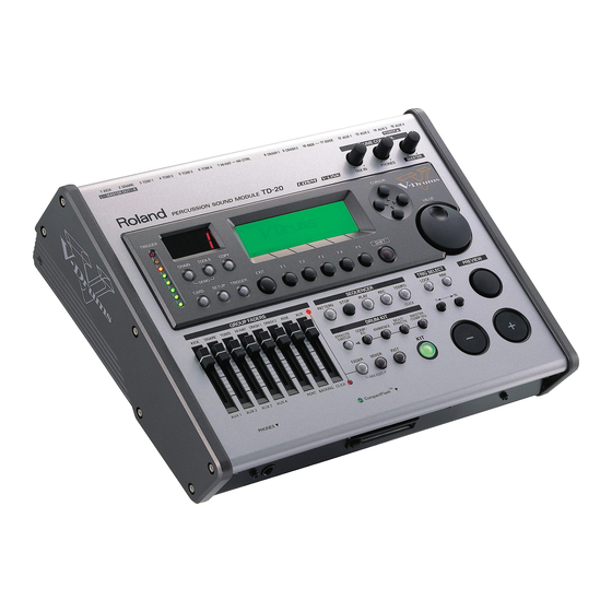
V-drums percusion sound module
Hide thumbs
Also See for V-Drums TD-20:
- Owner's manual (112 pages) ,
- Manual (76 pages) ,
- Cautions on using (1 page)
Table of Contents
Advertisement
Quick Links
Owner's Manual
We'd like to take a moment to thank you for purchasing the Roland Percussion Sound Module TD-20.
201b
Before using this unit, carefully read the sections entitled: "IMPORTANT SAFETY
INSTRUCTIONS" (p. 2), "USING THE UNIT SAFELY" (p. 3), and "IMPORTANT NOTES"
(p. 5). These sections provide important information concerning the proper operation
of the unit. Additionally, in order to feel assured that you have gained a good grasp
of every feature provided by your new unit, Owner's manual should be read in its
entirety. The manual should be saved and kept on hand as a convenient reference.
234
* CompactFlash and
are trademarks of SanDisk Corporation and licensed by
CompactFlash association.
235
* Roland Corporation is an authorized licensee of the CompactFlash™ and CF logo (
trademarks.
236
* Fugue © 2004 Kyoto Software Research, Inc. All rights reserved.
202
Copyright © 2004 ROLAND CORPORATION
All rights reserved. No part of this publication may be reproduced in any form without the
written permission of ROLAND CORPORATION.
)
Advertisement
Table of Contents

Related Manuals for Roland V-Drums TD-20


Summary of Contents for Roland V-Drums TD-20
- Page 1 Owner’s Manual We’d like to take a moment to thank you for purchasing the Roland Percussion Sound Module TD-20. 201b Before using this unit, carefully read the sections entitled: “IMPORTANT SAFETY INSTRUCTIONS” (p. 2), “USING THE UNIT SAFELY” (p. 3), and “IMPORTANT NOTES”...
-
Page 2: Important Safety Instructions
WARNING: To reduce the risk of fire or electric shock, do not expose this apparatus to rain or moisture. CAUTION RISK OF ELECTRIC SHOCK DO NOT OPEN ATTENTION : RISQUE DE CHOC ELECTRIQUE NE PAS OUVRIR CAUTION: TO REDUCE THE RISK OF ELECTRIC SHOCK, DO NOT REMOVE COVER (OR BACK). -
Page 3: Using The Unit Safely
Do not attempt to repair the unit, or replace parts within it (except when this manual provides specific instructions directing you to do so). Refer all servicing to your retailer, the nearest Roland Service Center, or an authorized Roland distributor, as listed on the “Information” page. - Page 4 • Immediately turn the power off, remove the power cord from the outlet, and request servicing by your retailer, the nearest Roland Service Center, or an authorized Roland distributor, as listed on the “Information” page when: • The power-supply cord, or the plug has been damaged;...
-
Page 5: Important Notes
However, in certain cases (such as when circuitry related to memory itself is out of order), we regret that it may not be possible to restore the data, and Roland assumes no liability concerning such loss of data. Memory Backup 501b •... - Page 6 (including padding) that it came in, if possible. Otherwise, you will need to use equivalent packaging materials. • Use a cable from Roland to make the connection. If using some other make of connection cable, please note the following precautions.
-
Page 7: Table Of Contents
Function Buttons ([F1]–[F5])... 23 Changing Data Values... 23 Group Faders ... 24 Choosing Pads from the TD-20’s Top Panel ... 24 How to Play Patterns... 25 How to Turn the Metronome (Click) On/Off... 25 How to Adjust the Tempo ... 25 Adjusting the Display Contrast ... - Page 8 Contents Adjusting the Volume [F1 (VOLUME)]... 29 Assigning a Tempo for Each Kit [F2 (TEMPO)] ... 29 Playing Brushes [F3 (BRUSH)] ... 29 Output Level Monitor [F5 (MONITOR)]... 29 Naming a Drum Kit [F3 (NAME)]... 30 Playing Cross Stick [F5 (XSTICK)]... 30 Chapter 2.
- Page 9 Detecting Trigger Signal Attenuation (Retrigger Cancel) ... 48 Double Triggering Prevention (Mask Time)... 49 Rim/Edge Dynamic Response (Rim Gain)... 49 Rim Shots Response (Rim Shot Adjust)... 49 Cross Stick Threshold (XStick Thrshld)... 49 Playing Bow, Bell, and Edge (3-Way Triggering) ... 50 Naming a Trigger Bank [F5 (Name)] ...
- Page 10 MIDI Settings and Operations [F1 (MIDI)] ... 74 Setting the MIDI Channels for Each Part [F1 (MIDI CH)]... 74 MIDI Settings for the Entire TD-20 [F2 (GLOBAL)] ... 74 MIDI Messages for Detailed Performance Expressions [F3 (CTRL)]... 76 Switching Drum Kits via MIDI (Program Change) [F4 (PROG)] ... 76 Saving Data to an external MIDI Device (Bulk Dump) [F5 (BULK)] ...
-
Page 11: Features
Studio Flexibility of audio routing is important in the professional environment. The TD-20 lets you use all of the outputs in a very efficient way. Each sound of the drum kit can be assigned to one of the 10 individual outs. (Master out can be used as an individual pair. - Page 12 (Tap tempo, p. 53). Expansion Board The TD-20’s bottom panel provides the access for the future Expansion Board, which will not only add new sounds, but provides a system upgrade using Flash ROM (p. 86, p. 88).
-
Page 13: Panel Descriptions
Panel Descriptions Top Panel fig.top 1. Trigger Level Indicator This lights up and moves each time a trigger signal is received from a pad. It monitors the pad connection and is helpful when customizing trigger parameters. 2. LED Display Displays the Kit number (currently selected drum kit). 3. - Page 14 For access to (Compact Flash) memory card functions such as saving/loading data etc. (p. 70) 8. SETUP Button For access to functions that affect the TD-20 globally, such as MIDI parameters etc. (p. 74) 9. TRIGGER Button For access to trigger parameters (p. 44).
-
Page 15: Rear Panel
TD-20’s sounds, or to load data (pp. 74–77). 5. MIDI OUT/THRU Connector For using the TD-20/pads to play sounds in an external MIDI sound module, or recording/saving data to an external MIDI sequencer (pp. 74–77). -
Page 16: Front Panel
2. CompactFlash Card Slot Accepts a CompactFlash memory card (optional). Each memory card can store all settings of the TD-20, such as drum kits and sequencer performance data, etc. (p. 70) * The CompactFlash is the only memory card can be used by the... -
Page 17: Setting Up The Kit
This unit should be used only with a stand that is recommended by Roland. When using the unit with a stand recommended by Roland, the stand must be carefully placed so it is level and sure to remain stable. If not using a stand, you still need to make sure that any location you choose for placing the unit provides a level surface that will properly support the unit, and keep it from wobbling. -
Page 18: Connecting The Pads And Pedals
Setting Up the Kit Connecting the Pads and Pedals Using the provided cables, connect the pads, cymbals, hi-hat, and kick trigger. * When mounting a TD-20 on an MDS-20 drum stand, use the built-in connection cables. Set Up Example fig.Kit.e... -
Page 19: Connecting Headphones, Audio Equipment, Amps, Or Other Gear
Stereo set, etc. Phone type Stereo phone type The TD-20’s MIX IN jack allows you to play along with a CD or other audio sources. • To adjust the volume of the device connected to the MIX IN jack, turn the [MIX IN] knob on the TD-20’s top panel. -
Page 20: Turning On/Off The Power
No Sound When Hitting the Pads or Using the Pedals? Check the following points. When Using an Amp or Audio System • Is the amp or audio system connected to the TD-20’s MASTER OUT jacks? • Is the input of the amp or audio system properly connected? •... -
Page 21: Connecting The Hi-Hat (Vh-12) And Setting The "Vh Offset
Connecting the Hi-Hat (VH-12) and Setting the “VH Offset” Connecting the Hi-Hat TRIGGER OUTPUT jack TRIGGER INPUT HI-HAT jack Adjusting the Offset When using the VH-12, the “VH Offset” needs to be set up. 1. Loosen the clutch of the top hi-hat and let it sit on the bottom hi-hat. -
Page 22: Listening To The Demo Song
Listening to the Demo Song The internal demo song features the TD-20’s expressive capabilities and top quality sounds. The drums on this song were recorded from the TD-20 system to a sequencer in real time. 1. Press [CHAIN] and [TOOLS] simultaneously. -
Page 23: Button Operation And Displays
Operations common to all aspects TD-20 operations. Saving Your Settings Every time you change a value during the editing process, it’s automatically stored in the TD-20’s memory. There’s no “write/save” process. (except when using a memory card) Buttons, Sliders, Dial and... -
Page 24: Group Faders
When using a rim capable pad, [RIM] lets you know you’re editing the rim. [PREVIEW] plays the sound in the display. So it’s easy to edit with only the TD-20 and a pair of headphones. * When you select the hi-hat (trigger number 7), you can sound the closed hi-hat by holding down [SHIFT] and pressing [PREVIEW]. -
Page 25: How To Play Patterns
About the Preset Drum Kits The TD-20 is shipped from the factory with 50 pre-loaded drum kits. After changing the settings, you can restore the factory settings at any time (p. 69). These drum kits are... -
Page 26: Playing Methods
Playing Methods Pad (PD-125/105) fig.Play-Head.e Head Shot Hit only the head of the pad. With certain snare sounds, playing position will change the nuance of the sound. fig.Play-Rim.e Rim Shot Strike the head and the rim of the pad simultaneously. fig.Play-Cross.e Cross Stick Only strike the rim of the pad. -
Page 27: Cymbal (Cy-15R/14C)
With certain ride sounds, playing position will change the nuance of the sound. * Only TRIGGER INPUT 10 RIDE corresponds to the positional sensing. About the instruments corresponding to each playing method, refer to p. 95. Playing Methods Roland logo... -
Page 28: Chapter 1. Drum Kit Settings [Kit]
A: Drum Kit Name B: Overall Kit Effects On/Off status (p. 38) Pressing [KIT] always takes you back to the “DRUM KIT” screen, from any Edit mode in the TD-20. Selecting a Drum Kit from the List [F1 (LIST)] You can select a drum kit by accessing the list of available kits. -
Page 29: Kit Parameters [F2 (Func)]
Kit Parameters [F2 (FUNC)] 1. Press [KIT] - [F2 (FUNC)]. 2. Press [F1]–[F3] and [CURSOR (up/down)] to select the parameter. 3. Use [+/-] or [VALUE] to make settings. Adjusting the Volume [F1 (VOLUME)] fig.01-003_70 Parameter Value Description Kit Volume 0–127 Volume of the entire drum Pedal HH Volume 0–127... -
Page 30: Naming A Drum Kit [F3 (Name)]
Chapter 1. Drum Kit Settings [KIT] Naming a Drum Kit [F3 (NAME)] Each kit’s name can use up to 12 characters. fig.01-005_70 1. Press [KIT] - [F3 (NAME)]. The “DRUM KIT NAME” screen appears. 2. Press [CURSOR (left/right)] to move the cursor to the character to be changed. -
Page 31: Chapter 2. Drum Instrument Settings [Inst]
* You can change the pad to be locked by pressing TRIG SELECT [1] or [15] even if the [LOCK] is lit. Assign an Instrument to a All the TD-20 sounds are referred to as instruments (INST). fig.02-001_70 1. Press [INST]. -
Page 32: Selecting An Instrument From The List [F1 (List)]
Chapter 2. Drum Instrument Settings [INST] Selecting an Instrument from the List [F1 (LIST)] Here you can select from the list of all available instruments. fig.02-003_70 1. Press [INST] - [F1 (LIST)]. The “INST LIST” screen appears. 2. Strike a pad. The settings screen for the struck pad appears. - Page 33 KICK fig.02-KICK_70 Parameter Value [F1 (SHELL)] Shell Depth NORMAL, DEEP1–2 Beater Type FELT, WOOD, PLASTIC [F2 (HEAD)] Head Type CLEAR, COATED, PINSTRIPE Head Tuning -480–+480 [F3 (MUFFLE)] Muffling OFF, TAPE1–2, BLANKET, WEIGHT Snare Buzz OFF, 1–8 [F4 (MIC)] Mic Position OUTSIDE2–1, STANDARD, INSIDE1–2 SNARE...
- Page 34 Chapter 2. Drum Instrument Settings [INST] CRASH/SPLASH/CHINA/RIDE fig.02-CYM_70 Parameter Value [F1 (SIZE)] Size 1”–40” [F2 (SIZZLE)] Sizzle Type OFF, RIVET, CHAIN [F3 (SUSTAIN)] Sustain -31–+31 [F4 (MIC)] Mic Position OUTSIDE2–1, STANDARD, INSIDE1–2 Other Instruments fig.02-005_70 Parameter Value Pitch -480–+480 Decay Time -31–+31 You can edit the instruments of the head and rim simultaneously.
-
Page 35: Using Pads/Pedal As Controllers [F3 (Control)]
Using Pads/Pedal as Controllers [F3 (CONTROL)] 1. Press [INST] - [F3 (CONTROL)]. 2. Strike a pad. The settings screen for the struck pad appears. You can select by using [TRIG SELECT]. 3. Press [F1]–[F5] and [CURSOR (up/down)] to select the parameter. 4. -
Page 36: Midi Settings For Each Pad [F3 (Midi)]
Chapter 2. Drum Instrument Settings [INST] MIDI Settings for Each Pad [F3 (MIDI)] Tx Channel: CH1–CH16, GLOBAL MIDI transmit channel for each pad. GLOBAL: Transmits on the same channel as the drum kit part (p. 74). Note No.: 0 (C -)–127 (G 9), OFF OFF: Note messages are not transmitted. -
Page 37: Chapter 3. Mixer Settings
Chapter 3. Mixer Settings Mixer Parameters [MIXER] Here you can adjust the volume, pan, etc. fig.03-001_70 1. Press [MIXER]. [MIXER] lights. 2. Use [F1]–[F5] or [CURSOR (up/down)] to select the parameter. 3. Use TRIG SELECT [1], [15], [RIM], or [CURSOR (left/right)] to select the instrument you wish to set. -
Page 38: Chapter 4. Effect Settings
Chapter 4. Effect Settings Effects On and Off Switches [EFFECTS SWITCH] These switches allow you to turn all individual effects and master effects on/off within each drum kit. fig.04-001_70 1. Press [EFFECTS SWITCH]. [EFFECTS SWITCH] lights, and the “EFFECTS SWITCH” screen appears. -
Page 39: Compressor (Comp)
Compressor (COMP) A compressor adjusts the envelope (changes in the volume over time) and changes the character of the sound in response to playing dynamics. fig.04-003_70 Parameter Value Attack EMPHASIS, CRUSH Type COMP SOFT 1–2, COMP MED 1–3, COMP HARD 1–2, LIMITER 1–2, EXPANDER 1–3 Time... -
Page 40: Ambience [Ambience]
Chapter 4. Effect Settings Ambience [AMBIENCE] You can choose the type of room where the drums are to be played and modify the sound. fig.04-005_70 1. Press [AMBIENCE]. [AMBIENCE] lights. 2. Press [F2]–[F4] or [CURSOR] to select the parameter. 3. Use [+/-] or [VALUE] to adjust the setting. 4. -
Page 41: Multi-Effects Parameters
Multi-Effects Parameters REVERB Adds reverberation to the sound, simulating an acoustic space. Parameter Value Description Room Type 1–5 Type of reverb PreDly 0–100.0 (ms) Time until the reverb is heard Time 0–127 Duration of reverbera- tion HiDamp 4.0k–12.5k (Hz), Frequency above which THRU the reverb is reduced in level... - Page 42 Chapter 4. Effect Settings FLANGER Produces a metallic resonance that rises and falls somewhat like a jet airplane taking off or landing. Parameter Value Description Delay 0–15.0 (ms) Tone of the flanger LFO Rate 1–128 Frequency of modulation Depth 0–127 Depth of modulation Feedback -98–98 (%)
-
Page 43: Master Effects [Master Comp/Eq]
Master Effects [MASTER COMP/EQ] A stereo compressor (limiter)/three-band equalizer provides final audio touches to the total sound of the TD-20. Can be used for each kit and/or all kits. fig.04-007_70 1. Press [MASTER COMP/EQ]. [MASTER COMP/EQ] lights. -
Page 44: Chapter 5. Trigger Settings [Trigger]
Chapter 5. Trigger Settings [TRIGGER] Selecting the Pad Type [F1 (BANK)] To be sure the TD-20 accurately receives signals sent from the pads, select the trigger type (the type of pads being used) for each trigger input. Trigger Type A trigger type is a group of trigger settings with values optimally adjusted for a particular pad. -
Page 45: Setting The Pad Sensitivity [F2 (Basic)]
Setting the Pad Sensitivity [F2 (BASIC)] When you are using pads made by other manufacturers, try adjusting the following parameters. 1. Press [TRIGGER] - [F2 (BASIC)]. [TRIGGER] lights, and the “TRIGGER BASIC” screen will appear. fig.05-TrigBasic_70 2. Use [CURSOR (up/down)] to select the parameter. -
Page 46: Hi-Hat Settings [F3 (Hi-Hat)]
2. After making the hi-hat settings, release your foot from the pedal, and while keeping your foot off the pedal, turn on the power to the TD-20. 3. Loosen the clutch screw and let the hi-hat rest naturally on the motion sensor unit. -
Page 47: Eliminate Crosstalk Between Pads [F4 (Xtalk)]
5. Set the trigger type for hi-hat to “VH11” (p. 44). 6. Press [TRIGGER] - [F3 (HI-HAT)]. * The “TRIGGER HI-HAT” screen appears. 7. Set the TD-20’s parameters as described below. Parameter Value Hi-Hat Type VH11/FD Foot Splash Sens CC Max... -
Page 48: Advanced Trigger Parameters [F5 (Advance)]
Chapter 5. Trigger Settings [TRIGGER] Advanced Trigger Parameters [F5 (ADVANCE)] The following parameters (Advanced Trigger Parameters) are automatically set to the most efficient values for each pad when you select the Trigger Type (p. 44), and don’t require adjustment, except if you experience any of the problems that are discussed in the explanation of each parameter. -
Page 49: Double Triggering Prevention (Mask Time)
You can also eliminate this problem of retriggering with the Mask Time setting. Mask Time does not detect trigger signals if they occur within the specified amount of time after the previous trigger signal was received. Retrigger Cancel detects the attenuation of the trigger signal level, and triggers the sound after internally determining which trigger signals were actually generated when the head was struck, while weeding out the other false trigger... -
Page 50: Playing Bow, Bell, And Edge (3-Way Triggering)
3Way Trigger: OFF, ON Connect as shown below, set 3Way Trigger to “ON.” fig.05-Ride.e Ride CY-15R or CY-12R/C BOW/BELL BOW/EDGE TD-20 Rear Panel Correspondences Between Playing Method and Trigger Input Playing Method TD-20 TRIGGER INPUT Bow Shot 10 RIDE head... -
Page 51: Chapter 6. Sequencer (Playback)
CD-ROM or equivalent means. The sound recordings contained in this product are the original works of Roland Corporation. Roland is not responsible for the use of the sound recordings contained in this product, and assumes no liability for any infringement of any copyright of any third party arising out of use of the sounds, phrases and patterns in this product. -
Page 52: Choosing A Pattern [Pattern]
Chapter 6. Sequencer (Playback) Choosing a Pattern [PATTERN] fig.06-003_70 1. Press [PATTERN]. [PATTERN] lights, and the “PATTERN” screen appears. 2. Use [+/-] or [VALUE] to select the pattern. * If you press [F5 (NEW)], an empty pattern with the lowest number is called up. -
Page 53: Tempo Adjustment
Synchronizing to the playback of an external sequencer In this case, the TD-20 will be the slave and an external sequencer will be master. 1. Connect the TD-20’s MIDI IN connector with a MIDI cable to the MIDI OUT connector of the external sequencer. -
Page 54: Part Settings [F2 (Part)]
Chapter 6. Sequencer (Playback) Part Settings [F2 (PART)] PATTERN PART screen (Only for User Pattern) fig.06-Part_70 Muting a Specific Part [F1 (MUTE)] You can mute specific parts in user patterns. 1. Press [PATTERN] - [F2 (PART)]. The “PATTERN PART” screen appears. 2. -
Page 55: Master Tuning
Instrument Numbers/Instrument Names You can change the tone by changing the instrument number. Selecting different variations within each instrument number changes the instrument name, with a different tone being selected. Instrument numbers correspond to the program numbers (1-128). Variation Tones These are slightly varied tone types found in an instrument number. - Page 56 Chapter 6. Sequencer (Playback) Selecting a Percussion Instrument from the List [F1 (LIST)] Here you can select from the list of all available instruments. 1. Press [CURSOR (up/down)] to select the note number you wish to set. 2. Press [F1 (LIST)]. The “PERCUSSION SET INST LIST”...
-
Page 57: Volume/Pan Settings For Each Part [F4 (Mixer)]
Volume/Pan Settings for Each Part [F4 (MIXER)] * Drum part cannot be set here. Set in the MIXER settings (p. 37). * To adjust volume/pan settings for each instrument of the percussion part, refer to p. 55. 1. Press [PATTERN] - [F2 (PART)]. The “PATTERN PART”... -
Page 58: Pattern Settings [F3 (Func)]
Chapter 6. Sequencer (Playback) Pattern Settings [F3 (FUNC)] Set various settings for the user patterns. Time Signature/Number of Measures/Tempo Settings [F1 (SETUP)] 1. Press [PATTERN]. The “PATTERN PART” screen appears. 2. Press [F3 (FUNC)] - [F1 (SETUP)]. The “PATTERN SETUP” screen appears. fig.06-PtnSetup_70 3. -
Page 59: Naming A Pattern [F5 (Name)]
Supplementary function for TAP and V-LINK Tap Reset Time: OFF, 0.2–4.0 (sec) This function automatically returns the pattern to the beginning if the set time interval elapses without the pad being hit again. This is the time interval that resets the pattern being used. -
Page 60: Setting The Click
Chapter 6. Sequencer (Playback) Setting the Click 1. Press [TEMPO] - [F1 (CLICK)]. The “CLICK SETTINGS” screen appears. fig.06-Click5_70 2. Press [CURSOR] to select the parameter. 3. Use [+/-] or [VALUE] to make settings. Parameter Value [F1 (INST)] Inst Refer to right col- umn. -
Page 61: Chapter 7. Sequencer (Recording/Editing)
Please keep in mind that even though there are 100 user patterns, the amount of memory available will be determined by how much data is recorded into TD-20. You can check the amount of memory available by pressing [TOOLS] - [F2 (INFO)] - [F1 (MEMORY)]. - Page 62 Chapter 7. Sequencer (Recording/Editing) (2) Set the Time Signature, the Number of Measures, and the Tempo 1. In the “PATTERN” screen, press [F3 (FUNC)] - [F1 (SETUP)]. The “PATTERN SETUP” screen appears. fig.07-Rec2-1_70 2. Press [CURSOR] to select the parameter. 3.
-
Page 63: Checking The Tones And Phrases During Recording (Rehearsal)
(5) Set the Recording Method 1. In the “PATTERN” screen, press [REC]. [PLAY] flashes, and [REC] lights. The “PATTERN REC STANDBY” screen appears, and the click sound begins to play. fig.07-Rec5-1_70 2. Press [CURSOR (up/down)] to select the parameter. 3. Use [+/-] or [VALUE] to make settings. Parameter Value Description... -
Page 64: Editing A Pattern [F4 (Edit)]
Chapter 7. Sequencer (Recording/Editing) Editing a Pattern [F4 (EDIT)] You can edit user patterns. PATTERN EDIT screen (Preset Pattern) fig.07-PrstEdit_70 PATTERN EDIT screen (User Pattern) fig.07-UserEdit_70 Copying a Pattern [F1 (COPY)] Copy the pattern as is to the User patterns. fig.07-Cpy1 You can copy selected measures of a part or pattern. -
Page 65: Connecting Two Patterns [F2 (Append)]
Connecting Two Patterns [F2 (APPEND)] This connects two patterns to create one pattern. The pattern specified as “Dst” will be first, and the pattern specified as “Src” will be connected to it. The new pattern will be created in “Dst.” fig.07-Apd1 1. -
Page 66: Deleting A Pattern [F4 (Delete)]
Chapter 7. Sequencer (Recording/Editing) Pattern Part Measure Pattern to be Part to be Measures to be erased erased erased (First Measure–Last Measure) 6. Press [F5 (ERASE)]. The confirmation screen appears. fig.07-Ers5_70 7. Press [F5 (EXECUTE)]. * To cancel, press [F1 (CANCEL)]. Deleting a Pattern [F4 (DELETE)] This deletes the pattern performance, beat, measure length, part, and all other settings, creating a empty pattern. -
Page 67: Saving Patterns To A Memory Card [F5 (Card)]
The CompactFlash indicator light, and the “PATTERN CARD” screen appears. * If you insert a card being used for the first time by the TD-20, display shows “Unformatted!” Refer to Formatting a Memory Card [F4 (FORMAT)] (p. 72) and initialize it. - Page 68 Card [F2 (LOAD)] Patterns saved on a memory card can be loaded into the TD- 1. Insert a CompactFlash card into the CompactFlash card slot on the TD-20’s front panel. 2. Press [PATTERN] - [F4 (EDIT)]. The “PATTERN EDIT” screen appears.
-
Page 69: Chapter 8. Copy Function [Copy]
Chapter 8. Copy Function [COPY] You can copy drum kits, instruments, etc. to the destination of your choice. Copying will overwrite the data that was in the new destination. So take caution when performing this operation. 1. Press [COPY]. [COPY] lights, and the “COPY” screen appears. If a CompactFlash card is inserted into the CompactFlash card slot, the CompactFlash indicator also lights (p. -
Page 70: Chapter 9. Using A Compactflash Memory Card [Card]
[CARD] AND the CompactFlash indicator light, and the “CARD MENU” screen appears. * If you insert a card being used for the first time by the TD-20, display shows “Unformatted!” Refer to p. 72 and initialize it. 3. Press [F1 (SAVE)]. -
Page 71: Naming A Backup [F4 (Name)]
Chapter 9. Using a CompactFlash Memory Card [CARD] Loading Data from a Memory Card [F2 (LOAD)] Data saved on a memory card can be loaded into the TD-20. 1. Insert the CompactFlash card into the CompactFlash card slot on the TD-20’s front panel. -
Page 72: Deleting Data From A Memory Card [F3 (Delete)]
6. Press [F5 (EXECUTE)] to delete the backup. Formatting a Memory Card [F4 (FORMAT)] When a card is being used for the first time by the TD-20, you must execute the following procedure to initialize the card. (This prepares the card for use with the TD-20.) When a card is initialized, all data on that card will be lost. -
Page 73: Checking The State Of A Memory Card [F5 (Info)]
Checking the State of a Memory Card [F5 (INFO)] 1. Insert a CompactFlash card into the CompactFlash card slot on the TD-20’s front panel. 2. PRESS [CARD]. [CARD] AND the CompactFlash indicator light, and the “CARD MENU” screen appears. 3. Press [F5 (INFO)]. -
Page 74: Chapter 10. Settings For The Entire Td-20 [Setup]
MIDI Settings and Operations [F1 (MIDI)] Setting the MIDI Channels for Each Part [F1 (MIDI CH)] For each part, you can specify the channel on which the TD-20 will receive and transmit MIDI messages. 1. Press [SETUP]. [SETUP] lights. 2. Press [F1 (MIDI)] - [F1 (MIDI CH)]. - Page 75 Suppose that when data was saved via bulk dump (p. 77), the TD-20’s Device ID was set to “17.” When re-transmitting this data back to the TD-20, it won’t receive if the Device ID is set to something other than “17.”...
-
Page 76: Midi Messages For Detailed Performance Expressions [F3 (Ctrl)]
Chapter 10. Settings for the Entire TD-20 [SETUP] MIDI Messages for Detailed Performance Expressions [F3 (CTRL)] 1. Press [SETUP]. [SETUP] lights. 2. Press [F1 (MIDI)] - [F3 (CTRL)]. The “MIDI CONTROL” screen appears. fig.10-MidiCtrl_70 3. Press [CURSOR (up/down)] to select the parameter. -
Page 77: Saving Data To An External Midi Device (Bulk Dump) [F5 (Bulk)]
“Do not receive System Exclusive messages.” Loading Data to the TD-20 At this time, all the TD-20’s current data is overwritten. Make sure you have made the needed backup. 1. Connect the TD-20’s MIDI IN connector with a MIDI cable to the MIDI OUT connector of the external sequencer. -
Page 78: Selecting Output Destinations [F2 (Output)]
Chapter 10. Settings for the Entire TD-20 [SETUP] Selecting Output Destinations [F2 (OUTPUT)] Here you can select the output destination for each TRIGGER INPUTs, sequencer parts, and the sound input from the MIX IN jack. Output Destination for the Drum Instruments 1. -
Page 79: Setting The Switches [F3 (Control)]
4. Use [+/-] or [VALUE] to select the function for foot switches. Chapter 10. Settings for the Entire TD-20 [SETUP] 5. When setting to “USER,” press [CURSOR] to move the cursor to “SW1” or “SW2.” 6. Use [+/-] or [VALUE] to select the functions for SW1 and SW2. -
Page 80: Using Pads As Switches [F2 (Pad Sw)]
Chapter 10. Settings for the Entire TD-20 [SETUP] Using Pads as Switches [F2 (PAD SW)] Pads connected to TRIGGER INPUT 15 (AUX4) and/or 14 (AUX3) can be set to switch drum kits and play back patterns. 1. Connect the pad(s) to the TRIGGER INPUT 15 (AUX 4) and/or 14 (AUX3). -
Page 81: Adjusting The Display Contrast [F5 (Lcd)]
Adjusting the Display Contrast [F5 (LCD)] The display contrast is strongly influenced by the location of the TD-20 and the lighting of the room it’s in. Adjust this parameter when needed. 1. Press [SETUP]. [SETUP] lights. 2. Press [F4 (OPTION)] - [F5 (LCD)]. -
Page 82: Chapter 11. Drum Kit Chain [Chain]
Chapter 11. Drum Kit Chain [CHAIN] Drum Kit Chain allows you to step through the drum kits of your choice and in the order you want. The TD-20 lets you create and store 16 different chains of up to 32 steps each. -
Page 83: Naming A Drum Kit Chain [F5 (Name)]
Naming a Drum Kit Chain [F5 (NAME)] Each chain’s name can use up to 12 characters. fig.11-ChainName_70 1. Select the drum kit chain you want to name in the “DRUM KIT CHAIN” screen. 2. Press [F1 (C EDIT)] - [F5 (NAME)]. The “CHAIN NAME”... -
Page 84: Chapter 12. Other Functions [Tools]
For example, by using the TD-20 and Edirol DV-7PR together, you can use the pads connected to the TD-20 to switch the Edirol DV-7PR’s images (clips/palettes). * In order to use V-LINK with the TD-20 and Edirol DV-7PR, you will need to make connections using an Edirol UM-1X/ UM-1SX (sold separately). -
Page 85: Using V-Link
* The Performance data recorded in the backing part of the sequencer is transmitted on V-LINK MIDI Ch (p. 75). * Set V-LINK Device ID (p. 75) to match the device ID number of the video equipment which is controlled by the TD-20. Chapter 12. Other Functions [TOOLS] V-LINK function Palette 1–20... -
Page 86: About Expansion Board
Expansion boards (optional) are cards that allow you to upgrade the system and add new instruments and drum kits. The bottom panel of the TD-20 has a slot that allows expansion boards to be installed. Install only the specified circuit board (SOUND & SYSTEM EXPANSION BOARD for TD-20). - Page 87 4. While positioning the holes on the board over the board holders, carefully insert the connector on the board into the socket on the TD-20. Make sure the connector is securely connected, and that all three board holders project through the holes.
-
Page 88: À Propos Des Carte D'extension
Le panneau du dessous du TD-20 a un créneau permettant l’installation des cartes d’extension. N’installez que la ou les carte de circuits imprimés spécifiée. - Page 89 4. Pendant que vous alignez les trous de la carte au-dessus des supports, insérez délicatement le connecteur sur la carte dans la prise du TD- 20. Assurez-vous que le connecteur est raccordé correctement et que les trois supports s’emboîtent bien dans les trous. 5.
-
Page 90: Messages And Error Messages
Messages and Error Messages This section lists the messages (error messages) that the TD-20 produces and explains the meaning of each message, giving you the appropriate action to take. fig.Message_70 When an indication of “ACCEPT” is shown above [F5] as in the figure, pressing that button will close the message window. - Page 91 Action Correct the receive address. If the same error message is displayed repeat- edly, there is a problem with the MIDI messag- es that are being transmitted to the TD-20. Make the interval of the data shorter. Action – –...
-
Page 92: Drum Instrument List
Drum Instrument List Name Remark KICK 22”Birch 22”Solid 22”StdMple K 22”Maple 24”Carbon 22”CbnMple K 22”GT 22”TitanHp K 22”Mahogny K 20”Lite 22”RoseWd 22”Oak Recording1 K Recording2 K Universal BigOpen JazzCombo1 K JazzCombo2 K Cannon Roto Booth Ballad Swing Heavy Fusion Latin Meat Pillow DryMed... - Page 93 Name Remark 12”Birch T1 12”Birch T1R 13”Birch T2 13”Birch T2R 16”Birch T3 16”Birch T3R 18”Birch T4 18”Birch T4R 12”GT 12”GT 13”GT 13”GT 16”GT 16”GT 18”GT 18”GT 10”Univ 10”Univ 12”Univ 12”Univ 14”Univ 14”Univ 16”Univ 16”Univ 12”Clasc T1 12”Clasc T1R 13”Clasc T2 13”Clasc T2R 16”Clasc T3 16”Clasc T3R...
- Page 94 Drum Instrument List Name Remark SPLASH 6”SplazhSpBw 6”SplazhSpEg 8”Thin SpBw 8”Thin SpEg 8”Bell SpBw 8”Bell SpEg 8”Open SpBw 8”Open SpEg 10”Med SpBw 10”Med SpEg CHINA 12”PgyBack 12”PgyBackEg 16”Swish 16”Swish 18”CB Low 18”CB Low Eg 20”U-China China PgBack Crash PgBack RIDE 18”PRideRd 18”PRideRdBl 18”PRideRdEg...
- Page 95 TD-20. Reproduction or duplication of any of the sound contained in the TD-20, either as they exist on this sound module or by any means of reformatting, mixing, filtering, re-...
-
Page 96: Note Number (Factory Settings)
Note Number (Factory Settings) Percussion Set 1. Latin Toys Note No. Bass Gliss GuitarScrtch WahGt1 Down WahGt1 Up WahGt2 Down WahGt2 Up CR78Guiro CR78Tamb TR808Clap TR808Cowbell TR808Maracas TR909Clap Hi-Q R8Slap Scratch2 Scratch3 Sticks Click MetroClick MetroBell Clap VibraSlap SquareBlock Beep Crotale SquareBlock 6"SplazhSpEg... - Page 97 Note No. Bongo Hi Bongo Lo Conga Hi Conga HiSlap Conga Lo Timbale Hi Timbale Lo Agogo Hi Agogo Lo Cabasa Maracas WhistleShort Whistle Guiro Short Guiro Long Claves Block Hi Block Lo Cuica Hi Cuica Lo TriangleCls Triangle Shaker SleighBell BellTree Castanet...
-
Page 98: Backing Instrument List
Backing Instrument List CC0 Name VOICES PIANO PIANO 1 PIANO 1W PIANO 1D PIANO 2 PIANO 2W PIANO 3 PIANO 3W HONKY-TONK HONKY-TONK W E. PIANO E.PIANO 1 DETUNED EP 1 60’S E.PIANO FM+SA EP HARD EP E.PIANO 2 BRIGHT FM EP CLAVI HARPSICHORD COUPLED HPS. - Page 99 * To switch instruments from the external MIDI device, send “0” on the CC32# (Control Change Bank Select) from the external MIDI device to the TD-20. * The value of the CC32# (Control Change Bank Select) that the TD-20 transmits is always “0.”...
-
Page 100: Midi Implementation Chart
MIDI Implementation Chart PERCUSSION SOUND MODULE Model TD-20 Function... Basic Default Channel Changed Default Mode Messages Altered Note Number : True Voice Note On Velocity Note Off After Key’s Touch Channel’s Pitch Bend 0, 32 6, 38 Control Change 16–19... - Page 101 PERCUSSION SOUND MODULE MIDI Implementation Chart Model TD-20 Function... Basic Default 1–16, OFF Channel Changed 1–16, OFF Default Mode 3 Mode Messages Altered ************** Note 0–127 Number : True Voice ************** Note On O 9nH, v = 1–127 Velocity Note Off...
-
Page 102: Specifications
Specifications TD-20: Percussion Sound Module Sound Generator Variable Drum Modeling Maximum Polyphony 64 Voices Instruments Drum Instruments: 560 Backing Instruments: 262 Drum Kits Drum Kit Chains 16 chains (32 steps per chain) Instrument Parameters V-EDIT (KICK): Shell Depth, Beater Type, Head Type, Head Tuning, Muffling,... -
Page 103: Output Impedance
It provides complete details concerning the way MIDI has been implemented on this unit. If you should require this publication (such as when you intend to carry out byte- level programming), please contact the nearest Roland Service Center or authorized Roland distributor. 962a... -
Page 104: Td-20 Block Diagram
INST Volume Backing Part MELODY INST BASS INST BACK 1 INST BACK 2 INST PATTERN /PART /BACKING TEMPO/CLICK/INST Click INST TD-20 Block Diagram MIXER MIXER /VOLUME /KIT VOL Volume KICK Volume Volume SNARE Volume Volume TOMS Volume Volume HI-HAT Volume... - Page 105 SETUP MULTI MIXER /OUTPUT EFFECTS /PAN /MASTER MFX Send MFX Send MFX Send MFX Send MFX Send MFX Send MFX Send MFX Send MFX Send SETUP /OUTPUT MFX Send /DIRECT MFX Send MFX Send MFX Send MFX Send MFX Send MFX Send SETUP /OUTPUT...
-
Page 106: Index
Index Symbols +/- ... 14, 23 Numerics 3-WAY ... 48 Acoustic Drum Kit ... 32 Add Tambourine ... 33 ADVANCE ... 48 AMB SEND LEVEL ... 37 Amb Send Level ... 60 APPEND ... 65 Backing Instrument ... 98 Backing Part ... 57 BANK ... - Page 107 F RESET ... 81 Factory Reset ... 81 FADER ... 24, 37 FIXED ... 33 Fixed Hi-Hat ... 33 Foot Splash Sens ... 46 FOOT SW ... 79 FOOT SWITCH ... 15 Foot Switch ... 79 FORMAT ... 72 FUNC ... 29 Function Button ...
- Page 108 Index ONESHOT ... 58 Open Rim Shot ... 26 OPTION ... 80 Other Instruments ... 34 OUTPUT ... 78 Output ... 60 Output Destination ... 78 Output Level ... 29, 84 Pad ... 18, 21, 26 Pad Pattern ... 35 Pad Ptn Velocity ...
- Page 109 TAMB ... 33 TAP ... 58–59 Tap Ptn Mute Grp ... 35 Tap Reset Time ... 58–59 TEMPO ... 29 Tempo ... 25, 53, 58, 62 Tension ... 21 Threshold ... 45 Time ... 57 Time Signature ... 58, 60, 62 TIMESIG ...
-
Page 110: Preset Drum Kit List
Preset Drum Kit List No. Name No. Name 1 VPro 11 Spark! 2 Slamin’ 12 >>GT>> 3 METAL 13 Antique 4 JazzCombo 14 =BreakBeats= 5 OverDrive 15 Studio 6 Titanium 16 Groover 7 RotoKit 17 Mallet 8 UNIVERSE 18 Drumline 9 Skanky 19 JazzGig 10 Brushes... -
Page 111: Federal Communications Commission
Apparatus containing Lithium batteries ADVARSEL! Lithiumbatteri - Eksplosionsfare ved fejlagtig håndtering. Udskiftning må kun ske med batteri af samme fabrikat og type. Levér det brugte batteri tilbage til leverandøren. ADVARSEL Eksplosjonsfare ved feilaktig skifte av batteri. Benytt samme batteritype eller en tilsvarende type anbefalt av apparatfabrikanten. -
Page 112: North America
Information When you need repair service, call your nearest Roland Service Center or authorized Roland distributor in your country as shown below. PHILIPPINES AFRICA G.A. Yupangco & Co. Inc. 339 Gil J. Puyat Avenue EGYPT Makati, Metro Manila 1200, Al Fanny Trading Office...