Advertisement
Available languages
Available languages
Quick Links
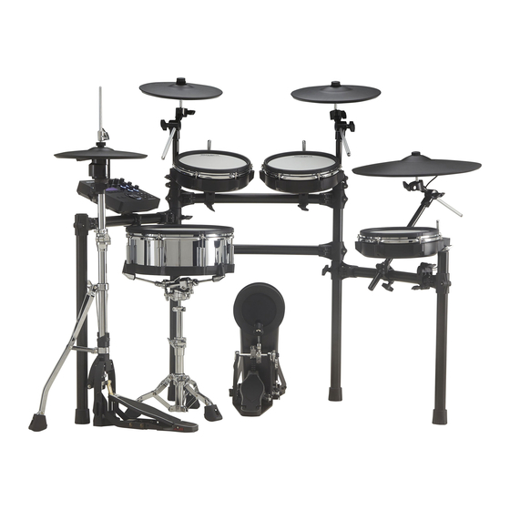
TD-27KV
Check the included items
1
As soon as you open the package, check to see that all items are included.
If anything is missing, please contact your dealer.
TD-27KV (Drum Set)
8 TD-27 (Drum sound module) x 1
Owner's Manuals
8 TD-27KV Setup Guide (this document)
8 PD-140DS (V-Pad digital snare) x 1
8 TD-27 Quick Start
8 CY-18DR (V-Cymbal digital ride) x 1
8 PD-140DS Owner's Manual
8 VH-10 (V-Hi-hat) x 1
8 CY-18DR Owner's Manual
8 KD-10 (Kick Pad) x1
8 VH-10 Owner's Manual
8 PDX-100 (V-Pad) (tom1, 2, 3) x 3
8 KD-10 Owner's Manual
8 CY-12C (V-Cymbal for crash 1) x 1
8 PDX-100 Owner's Manual
8 CY-13R (V-Cymbal for crash 2) x 1
8 CY-13R / CY-12C Owner's Manual
* The TD-27/PD-140DS/CY-18DR accessories are in
the respective packing cartons.
MDS-Standard 2 (Drum Stand)
* When checking the items included with the drum stand, refer to "MDS-Standard 2 Owner's
Manual. "
Assemble the drum stand (MDS-Standard 2)
2
Assemble the drum stand using the procedure described in "MDS-Standard 2 Owner's Manual. "
* This drum set illustration is for a right-handed player. If you want to set up for a left-handed player, assemble it as described in "Assembly
for a left-handed player" in "MDS-Standard 2 Owner's Manual. "
Cymbal mounts
Mount holder
Pad mounts
Attaching Various Parts to the
5
Drum Stand
Use the included drum key to attach the various parts.
* The settings explained in this guide are for a right-handed player. If you want to set up for a
left-handed player, refer to "Assembly for a Left-Handed Player" in the next page.
* For details on each part, refer to the owner's manual of each part.
Attach the drum sound module (TD-27)
1.
Use the included wing bolts to attach the
sound module mounting plate to the drum
sound module.
Roland logo faces
outward
Sound module mounting plate
2.
Loosen the hand knob of the drum stand
mount holder, and insert the sound module
mounting plate.
Hand knob of
mount holder
3.
Using the drum key included with the drum
sound module, adjust the angle of the sound
module mounting plate.
Installing the hi-hat (VH-10)
Position it so that the Roland logo on the farther
side, as viewed from the player.
Adjusting the position of the cymbal
Attach the cymbal
so that its center
Adjust the height
does not extend
of the rod so that
toward the back
the highest point
1.2 m
beyond the pipes
of the cymbal is
(47 inches)
of the stand (the
less than 1.2 meters
pipes at the back
(47 inches).
of the stand).
Mounting the snare (PD-140DS) on a snare stand
The PD-140DS can only be used with a commercially available snare stand.
* Make sure that the snare stand you are using is able to support a 14-inch shell.
Insert the plug of the connection cable into the PD-140DS's DIGITAL TRIGGER
OUT connector.
Protector
DIGITAL TRIGGER OUT connector
Connection cable
Use the protector to lock the connection.
*
5
1
0
0
0
6
8
7
9
1
-
0
1
*
Setup Guide
8 Cables
Dedicated connection cable x 1
(Packed with the TD-27)
Trigger cable x 1
Connection cable x 2
(Packed in the respective cartons
of the PD-140DS and CY-18DR)
* This package does not include a kick pedal, a hi-hat stand, and a
snare stand. Use with a commercially available kick pedal, hi-hat
stand, and snare stand.
* The drum key used to attach the pads is inside the packing carton
of the drum sound module.
Assembly procedure
1.2 m
(47 inches)
* For reasons of safety, do not spread the drum stand
wider than 1.2 meters (47 inches). Doing so can cause
the stand to fall over.
1.
Position the cymbal so that the convex portion
of the cymbal mount is aligned with the concave
portion of the bottom of the cymbal.
2.
Tighten the cymbal nut to obtain an appropriate
amount of sway.
* Use the cymbal nut and felt washer that are included with the
drum stand.
CRASH1
(CY-12C)
TD-27
HI-HAT
(VH-10)
SNARE
(PD-140DS)
OK
Adjusting the head tension
6
8
Adjust the tension so that the pad
responds to your strikes with the
4
4
1
appropriate feel.
2
2
3
1.
Adjust each tuning bolt little
by little, across the head as
7
7
5
5
indicated in the illustration.
2.
Adjust the tightness of each
tuning bolt so that the head is
tuning bolt
tensioned evenly.
Before using this unit, carefully read "USING THE UNIT SAFELY" and "IMPORTANT NOTES" of this document and accessories.
After reading, keep the document(s) where it will be available for immediate reference.
© 2020 Roland Corporation
Assembling the Hi-Hat (VH-10)
3
Clutch Screw
Hi-Hat
* "Roland" logo on the farther
side, as viewed from the
player
Motion Sensor Unit
* CONTROL OUT jack on the farther
side, as viewed from the player
Insulating Plate
* Sponge side up
Cymbal Rod
Compatible Stands
Diameter: 6.0–7.0 mm
(1/4 to 5/16 inches)
Diameter: 11.7 mm
(1/2 inches) Max.
Assembling the Kick (KD-10)
4
1.
Attach the kick pedal (commercially available) to the
KD-10.
Position the beater so that it strikes the center of the head,
then secure the kick pedal and KD-10 rmly in place.
* Take care not to pinch your ngers.
Beater
Install the kick pedal securely.
Reference
For details on the kick, refer to "KD-10 Owner's Manual. "
Attach the crash cymbal (CY-12C / CY-13R) and ride cymbal (CY-18DR)
Cymbal nut
Felt washer
"Roland" logo on
the farther side, as
viewed from the
player
Convex portion
CRASH2
(CY-13R)
TOM1
TOM2
(PDX-100)
(PDX-100)
(CY-18DR)
TOM3
(PDX-100)
KICK
(KD-10)
If you're using this unit on a V-Drums mat, on a Noise Eater (NE-10), or on
carpet, extending the anchor bolts will secure the unit in place, making it
easier for you to perform.
* When used on ooring, the anchor bolts may damage the oor.
* The tips of the anchor bolts are sharp. Handle with care.
Assembly procedure
1.
Remove the clutch included with the hi-
4.
Place the motion sensor unit with the
hat stand (commercially available) from
cymbal rod passing through the hole of
the cymbal rod.
the motion sensor unit.
* The clutch included with the hi-hat stand will not
* Position the CONTROL OUT jack on the farther side,
be used.
as viewed from the player.
* It is not necessary to remove the felt component
5.
(or rubber portion) on the hi-hat stand used for
Pass the hi-hat over the cymbal rod.
supporting the bottom cymbal.
Positioning the "Roland" logo on the farther
2.
Con rm that the cymbal rod is rmly
side, as viewed from the player will provide
secured.
the best sensitivity.
For instructions on tightening the cymbal
6.
With the hi-hat completely separated
rod, refer to the owner's manual for your
from the motion sensor unit, power-on
cymbal stand.
the TD-27.
* Looseness or play in the cymbal rod can make the
top hi-hat unstable, causing it to shake or turn, and
prevent proper functioning.
3.
With the sponge surface of the anti-
Separated
vibration plate facing upward, pass it
over the cymbal rod.
This will rest on top of the felt component (or
* When turning the VH-10 upside down, protect the
clutch and the sensor from damage. Handle the unit
rubber portion) of the hi-hat stand's cymbal
with care so that it is not dropped or overturned.
receiver.
Reference
For details on the hi-hat, refer to "VH-10 Owner's Manual. "
Assembly procedure
2.
Step on the kick pedal and make sure that it's properly
attached and in a stable position.
Check to make sure that the KD-10 and the kick pedal both
make contact with the oor.
Beater must hit the center
Beater must hit the center
of the striking surface
of the striking surface
Check to be sure they're making contact with the oor
Insert the plug of the connection cable
into the CY-18DR's DIGITAL TRIGGER OUT
connector.
DIGITAL TRIGGER OUT connector
Attach the toms (PDX-100)
Loosen
Tighten
Adjusting the head tension
Adjust the tension so that the pad responds to your
strikes with the appropriate feel.
RIDE
* Before using the pad, tighten the head so that the tension is
rather rm.
1
3
1.
Adjust each tuning bolt little
by little, across the head as
indicated in the illustration.
6
5
2.
Adjust the tightness of each
tuning bolt so that the head is
4
2
tensioned evenly.
tuning bolt
NOTE
Adjusting the head tension a ects only the head response,
and does not change the pitch of the sound as it would on an
acoustic drum.
Pitch adjustments are made by editing the sound in your drum
sound module. For details, refer to the "TD-27 Quick Start. "
Installing the kick (KD-10)
Adjusting the anchor bolts
When using on
the V-Drums mat,
Noise Eater, or carpet
clutch screw
motion sensor unit
Protector
Connection cable
Use the protector
to lock the
connection.
Rod
When using on the
oor
Advertisement

Related Manuals for Roland V-Drums TD-27KV


Summary of Contents for Roland V-Drums TD-27KV
- Page 1 KICK (KD-10) tuning bolt Installing the hi-hat (VH-10) Position it so that the Roland logo on the farther side, as viewed from the player. NOTE Adjusting the head tension a ects only the head response, Adjusting the position of the cymbal...
- Page 2 • Roland, BOSS, and V-Drums are either registered trademarks or produced when it’s played. However, since sound vibrations copyright owner.
- Page 3 クラッチ ・ スクリュー ているクラッチを、シンバル・ロッ ドか ンバル・ロッ ドに通します。 らはずします。 8 ケーブル類 8 TD-27(ドラム音源)× 1 8 取扱説明書 ハイハッ ト ※ CONTROL OUT 端子を演奏者から見て ※ Roland ロゴを演奏者 8 PD-140DS(V パッド・デジタル・スネア)× 1 8 TD-27KV セットアップ・ガイド(本書) ※ ハイハッ ト・スタン ドに付属のクラッチは、 奥側にします。 側から見て奥側に 使いません。 8 TD-27 クイック・スタート 8 CY-18DR(V シンバル・デジタル・ライド)× 1 専用接続ケーブル ×...
- Page 4 使用上のご注意 修理について 知的財産権について • 本製品は、T-Engine フォーラム(www.tron.org)の 注意 T-License 2.0 に基づきμT-Kernel ソースコードを利用し • 第三者の著作物(音楽作品、 映像作品、 放送、 実演、 その他) ています。 • お客様が本機または付属品を分解(取扱説明書に指示があ スタンドを使う前に安全を確認する の一部または全部を、権利者に無断で録音、録画、複製あ る場合を除く) 、改造された場合、以後の性能について保証 • Roland、BOSS、V-Drums は、日本国およびその他の国 るいは改変し、配布、販売、貸与、上演、放送などを行う 取扱説明書に記載の注意事項が守られていても、取 できなくなります。また、 修理をお断りする場合もあります。 におけるローラン ド株式会社の登録商標または商標です。 ことは法律で禁じられています。 り扱いによってはスタン ドから本機が落下したりスタ • 当社では、本機の補修用性能部品(製品の機能を維持す ン ドが転倒したりする可能性があります。使用にあ • 文中記載の会社名および製品名などは、各社の登録商標ま • 第三者の著作権を侵害する恐れのある用途に、本製品を使 るために必要な部品)を、製造打切後 6 年間保有していま たっては事前に安全を確認した上でお使いください。...
- Page 5 KICK Stimm- (KD-10) schraube Installieren der Hi-hat (VH-10) Das Roland-Logo muss sich vom Spieler aus gesehen auf der gegenüberliegenden Seite be nden. WICHTIG Das Spannen des Fells verändert nur das Spielgefühl und nicht (wie bei Einstellen der Position des Cymbal-Pads einer akustischen Trommel) die Tonhöhe.
- Page 6 Spielgeräusche erzeugt. Es ist aber möglich, Gerät sicher und stabil aufgestellt sind. • Verwenden Sie dieses Instrument nicht mit per Copyright bzw. Warenzeichen der Roland Corporation in den USA und/ dass bei Spielen dieses Geräts die entstehenden Vibrationen geschützten Audiodaten, wenn Sie keine Genehmigung oder anderen Ländern.
-
Page 7: Guide D'installation
(KD-10) Tirants de réglage Installation du charleston (VH-10) Positionnez-le de manière à ce que le logo Roland se trouve du côté opposé au batteur (de son point de vue). REMARQUE Le réglage de la tension de la peau a ecte seulement la Réglage de la position de la cymbale... - Page 8 • Ce document présente les spéci cations du produit à la date violations de droits d’auteurs de tiers découlant de l’utilisation • Roland, BOSS et V-Drums sont des marques déposées ou des de publication du document. Pour obtenir les informations les Débranchez l’ensemble des cordons/câbles avant de...
- Page 9 KICK (KD-10) bullone di accordatura Installare l’hi-hat (VH-10) Posizionate il logo “Roland” sul lato più lontano, rispetto al batterista. NOTA Regolando la tensione della pelle si in uenza solo la sua Regolare la posizione del piatto risposta, e non si cambia l’intonazione del suono come avviene Montate il piatto su un tamburo acustico.
-
Page 10: Modulo Sonoro
Non salite mai, ne ponete oggetti pesanti sull’unità. fate attenzione a nché tali suoni non divengano fonte di • Roland, V-Drums, e BOSS sono marchi di fabbrica registrati o violare i diritti di autore detenuti da una terza parte. Non ci disturbo per i vostri vicini. -
Page 11: Guía De Instalación
(KD-10) tornillo de a nación Instalación del charles (VH-10) Sitúelo con el logotipo de Roland en el lado más alejado, desde el punto de vista del músico. NOTA El ajuste de la tensión del parche afecta solamente a la Ajuste de la posición del platillo... - Page 12 • Utilice con cuidado los sensores de la unidad, así como los • La ley prohíbe realizar grabaciones de audio o vídeo, copias de dichas marcas por parte de Roland se realiza bajo licencia. Considere todas las cuestiones de seguridad antes enchufes y conectores de la misma.
-
Page 13: Guia De Instalação
(KD-10) parafuso de a nação Instalação do chimbal (VH-10) Posicione de forma que o logotipo “Roland” que no lado oposto, do ponto de vista de quem estiver tocando. OBSERVAÇÃO Ajustar a tensão da pele afeta apenas a resposta da pele e não Ajuste da posição do prato... - Page 14 Não assumimos qualquer pesados sobre ele • Roland, BOSS e V-Drums são marcas registradas ou comerciais proximidades. responsabilidade no que diz respeito a qualquer infração da Roland Corporation nos Estados Unidos e/ou em outros Caso contrário, você...
- Page 15 KICK passen. (KD-10) stembouten De hi-hat installeren (VH-10) Plaats het zodat het Roland-logo het verste weg vanuit het standpunt van de speler is. OPMERKING Als u de bovenvelspanning regelt, heeft dit alleen invloed op De positie van het cimbaal aanpassen de reactie van het bovenvel.
- Page 16 Ga niet boven op het apparaat staan en plaats er • Roland, BOSS en V-Drums zijn geregistreerde handelsmerken derde. Wij aanvaarden geen enkele verantwoordelijkheid voor geen zware voorwerpen op •...