Table of Contents
Advertisement
Quick Links
Read this manual carefully before you use this machine and keep it handy for future reference. For safe and correct use, be sure to read the Safety
Information in this manual before using the machine.
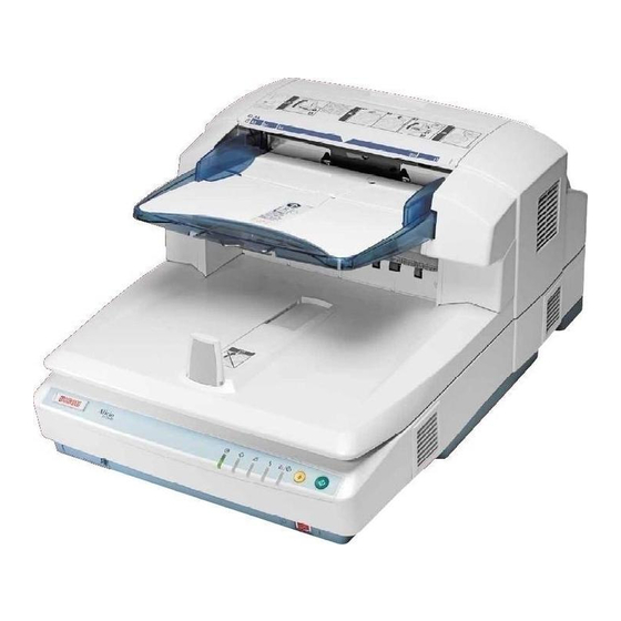
Image Scanner
Guide to Components
Setting up the Scanner
Installing Software
Setting Originals
Using the TWAIN Driver
Appendix
Operating Instructions
Advertisement
Table of Contents

Related Manuals for Ricoh IS760


Summary of Contents for Ricoh IS760
-
Page 1: Operating Instructions
Read this manual carefully before you use this machine and keep it handy for future reference. For safe and correct use, be sure to read the Safety Information in this manual before using the machine. Image Scanner Operating Instructions Guide to Components Setting up the Scanner Installing Software Setting Originals Using the TWAIN Driver Appendix... - Page 2 If you have any questions concerning the legality of copying or printing cer- tain items, consult with your legal advisor. Power Source Color Scanner: 120V, 60Hz, 10A or more Please be sure to connect the power cord to a power source as above. Trademarks Adobe, PostScript, and Acrobat are trademarks of Adobe Systems Incorporated.
-
Page 3: Table Of Contents
Connecting the SCSI Cable (When the Scanner is at the End of the Daisy Chain) ...24 Connecting the SCSI Cable (When the Scanner is not at the End of the Daisy Chain) ...26 Using the Scanner only with the SCSI Connection ... 27 Connecting with USB Interface ...28... - Page 4 When [Gray Scale] or [256 Colors] is Selected... 83 When [8 Colors] or [8 Colors(Photo)] is Selected ... 83 When [16770K colors] is Selected... 84 Options ... 85 Image Processing Unit Type B... 85 IEEE1394 Interface Unit Type IS760 ...85 Specifications...86 INDEX... 88...
-
Page 5: Safety Information
Safety Information When using this machine, the following safety precautions should always be fol- lowed. Safety During Operation In this manual, the following important symbols are used: R WARNING: Indicates a potentially hazardous situation which, if instructions are not followed, could result in death or serious injury. R CAUTION: Indicates a potentially hazardous situation which, if instructions are not followed, may result in minor or moderate injury or damage to property. - Page 6 Have all in- spections, adjustments, and repairs inside the scanner performed by an authorized dealer only. • Do not attempt to modify this scanner in any way. Modification can cause fire or electrical shock.
- Page 7 • Be careful not to pinch your fingers when closing the Automatic Document Feeder (ADF). • This scanner weighs approximately 72.8 lbs. • Make sure to lift it carefully with two persons or more so as to minimize physical strain.
-
Page 8: Energy Star Program
Energy Star Program The ENERGY STAR Guidelines intend to establish an international energy-saving system for developing and introducing energy-efficient office equipment to deal with environmental is- sues, such as global warming. When a product meets the ENERGY STAR Guidelines for energy efficiency, the Partner shall place the ENERGY STAR logo onto the machine model. -
Page 9: Manuals For This Scanner
❖ ❖ ❖ ❖ Quick Installation Guide Describes how to install the scanner. ❖ ❖ ❖ ❖ Operating Instructions (this manual) Provides all of the information how to install, set up, and use the scanner. This manual is provided as a PDF file. Note... -
Page 10: How To Read This Manual
How to Read This Manual Symbols The following set of symbols is used in this manual. R WARNING: This symbol indicates a potentially hazardous situation that might result in death or serious injury when you misuse the machine without following the in- structions under this symbol. -
Page 11: Guide To Components
Rotary Switch Use to set SCSI ID. DIP Switches Use to set the operation mode of this scanner. ⇒ p.10 “DIP Switches” Hard Reset Switch This switch resets the power to the scan- ner. Use this switch when validate the settings of the DIP Switches or the Rotary Switch. - Page 12 Guide to Components Pressure Panel Holds the originals down on the Expo- sure Glass. Background Panel for Exposure Glass Panel to set the background color for the original in black or white when you place the original on the exposure glass. ⇒ p.54 “Changing the Color of the Background Panel for the Exposure Glass”...
-
Page 13: Understanding Indicators
Scanning operation in progress Originals are set to the ADF Error When SADF mode or during standby for the manual scan Guide to This Scanner ADC126S Power Off No originals are set to the ADF No error or the current status... -
Page 14: Dip Switches
SCSI cable longer than recommended, or a cable out of the standard. In that case, turn the DIP Switch No.2 ON (SCSI synchronous transmission dis- abled). ❒ When the scanner is connected to the middle of the daisy chain, set the DIP Switch No.3 ON. Function... -
Page 15: Setting Up The Scanner
2. Setting up the Scanner This section explains how to setup the scanner to get it ready for use, and how to make necessary connections. Confirmations Before the Setup Location, Space and Environment ❖ ❖ ❖ ❖ Location R WARNING: •... - Page 16 Setting up the Scanner ❖ ❖ ❖ ❖ Environment Important ❒ Do not set up the scanner in any of the following types of locations. It may be the cause of the malfunction. • In a location exposed to direct sunlight •...
-
Page 17: Disengaging The Lock For Transportation
Disengaging the lock for transportation In this section, we explain how to disengage the lock after you take the scanner out of the package for transportation. A A A A Remove two lock screws fixed on the back of this machine. - Page 18 Setting up the Scanner C C C C The removed lock screws are to be kept on the back of the Pressure Panel as follows: A Lift the Pressure Panel and carefully pull out the Background Panel that is fixed with the Velcro.
- Page 19 Confirmations Before the Setup Note ❒ Be sure to set the lock lever to the “Unlock” position. Turning the power on leaving the lock lever to the “Lock” position could result not only in fail- ure in scanning but in malfunction of the machine.
-
Page 20: Installing Options
B B B B Remove the three screws on the lower back surface of the product. C C C C Pull out the scanner control unit by pulling the black ribbon on the center of the board. Important ❒ The control unit is heavy. Please take care not to drop it when pulling it out. -
Page 21: Control Unit
Close the scanner control unit cover and fix with seven screws, then insert the scanner control unit into the main unit. Note ❒ Be sure to place the scanner on the level surface when inserting the scanner control unit. ❒ Insert the scanner control unit till you see the screw holes. -
Page 22: Installing The Ieee1394 Interface Board
B B B B Remove the three screws on the lower back surface of the product. C C C C Pull out the scanner control unit by pulling the black ribbon on the center of the board. Important ❒ The control unit is heavy. Please take care not to drop it when pulling it out. - Page 23 D D D D Remove the seven screws on the cover of the scanner control unit. E E E E Open the cover of the scanner control unit. F F F F Remove the USB 2.0 interface board fixed with 6 screws.
- Page 24 Close the scanner control unit cover and fix with seven screws, then insert the scanner control unit into the main unit. Note ❒ Be sure to place the scanner on the level surface when inserting the scanner control unit. ❒ Insert the scanner control unit till you see the screw holes.
-
Page 25: Connecting To The Computer
IEEE1394 interface. An optional board will be required to connect with IEEE1394. Important ❒ Do not turn the power of the scanner ON before the software installation. If you run the "Found New Hardware Wizard" beforehand, you will not be able to in- stall the software correctly. -
Page 26: Setting The Scsi Id
Setting up the Scanner Setting the SCSI ID A A A A Open the cover of the switch box on the lower left of the frontside of the scanner. Note ❒ Push the knob of the cover to the left and pull the cover to open. -
Page 27: Setting The Scsi Id Automatically
SCSI device, set the SCSI ID manually. A A A A Open the cover of the switch box on the lower left of the frontside of the scanner. Note ❒ Push the knob of the cover to the left and pull the cover to open. -
Page 28: Connecting The Scsi Cable (When The Scanner Is At The End Of The Daisy Chain)
Setting up the Scanner Connecting the SCSI Cable (When the Scanner is at the End of the Daisy Chain) A A A A Shut down the computer and all of the SCSI connected devices. B B B B Daisy chain the computer, scanner and SCSI connected devices. - Page 29 Connecting to the Computer Note ❒ Press the Hard Reset Switch if you changed the SCSI ID while the power is ON. ⇒ p.34 “Using the Hard Reset Switch”...
-
Page 30: Connecting The Scsi Cable (When The Scanner Is Not At The End Of The Daisy Chain)
Setting up the Scanner Connecting the SCSI Cable (When the Scanner is not at the End of the Daisy Chain) A A A A Shut down the computer and all of the SCSI connected devices. B B B B Daisy chain the computer, scanner and SCSI connected devices. -
Page 31: Using The Scanner Only With The Scsi Connection
ON. ⇒ p.34 “Using the Hard Reset Switch” Using the Scanner only with the SCSI Connection You can set the scanner to the SCSI synchronous transmission for high-speed data transfer and shorten the total scan time. The USB and the optional IEEE1394 connection cannot be used when the SCSI synchronous transmission is set. -
Page 32: Connecting With Usb Interface
As for the recommended cables, please ask your service representative. ❒ You can connect the scanner to two computers at the same time. One with the SCSI interface, and one with the USB 2.0 interface. Though, you cannot use the scanner at the same time from two computers. -
Page 33: Connecting With Ieee1394 Interface
PC. Please use the recommended IEEE1394 interface board for your PC. As for the recommended boards, please ask you service representative. ❒ You can connect the scanner to three computers at the same time. One with a SCSI interface, and two with the optional IEEE1394 interface. Though, you cannot use the scanner at the same time from three computers. - Page 34 Setting up the Scanner B B B B Confirm the DIP Switch No.2 is in the ON position. Note ❒ If the DIP Switch No.2 is set to OFF, set it to ON. If the switch is set to OFF, "Found New Hardware Wizard"...
-
Page 35: Connecting To A Power Source
Connecting to a Power Source This section explains how to connect this machine to a power source, using a bundled AC power cord. R WARNING: • Do not use with a power source with a voltage different from the specified voltage. Do not use a power outlet with multiple devices plugged in. - Page 36 Setting up the Scanner Important ❒ Be sure to remove the lock screws. Turning the power on without remov- ing the screws could result not only in failure in scanning but in malfunc- tion of this machine. C C C C Confirm that the lock lever located on the back of the machine is set to the “Unlock”...
-
Page 37: Turning The Power On/Off
There is no order to turn on the power when you connect the scanner with USB or IEEE1394 interface. You can turn on either the scanner or the computer first. Turning the Power Off There is no order to turn off the power. You can turn off either the scanner or the computer first. ADC101S... -
Page 38: Using The Hard Reset Switch
You need to hard reset the scanner when validate the settings of the DIP Switch- es or the Rotary Switch. To hard reset the scanner, you can turn off the scanner and turn it on again, or follow the procedures below. -
Page 39: Installing Software
3. Installing Software This machine can be used both as a TWAIN scanner and an ISIS scanner. A TWAIN driver and its applications are to be installed for the TWAIN scanner, and an ISIS driver and its applications are to be installed for the ISIS scanner. -
Page 40: Installing Twain Driver
Start the computer, retaining the power of the scanner OFF. Note ❒ If the power of the computer turns ON, retaining the power of the scanner ON, before driver installation, the "Found New Hardware Wizard" auto- matically starts. In this case, click [Cancel] button. - Page 41 - Changing the connecting interface When you change the connecting interface from the interface first installed, change the cable to the new interface and start from step D. "Scanner Driver(s), Utilities and Operating Instructions" CD-ROM is not required. Note ❒...
-
Page 42: Installing Desktopbinder Lite
This soft- ware is compatible with a TWAIN driver. You can use this software to scan doc- uments with this scanner. System Requirements Install DeskTopBinder Lite to the computer that meets the system requirements below. -
Page 43: Installing Desktopbinder Lite
Log on to the computer as a member of the Administrators group, for instal- lation to Windows 2000/XP, or Windows Server 2003. A A A A Start Windows, and then insert the supplied CD-ROM labeled “Scanner Driver(s), Utilities and Operating Instructions” into the CD-ROM drive of the client computer. -
Page 44: Installing Isis Driver
Installing Software Installing ISIS Driver When this machine is used as the ISIS scanner; it is necessary to install the ISIS driver to be used for the ISIS compliant applications. Preparation Start installation, retaining the power of the scanner OFF. -
Page 45: Installing Isis Driver
Start the computer, retaining the power of the scanner OFF. Note ❒ If the power of the computer turns ON, retaining the power of the scanner ON, before driver installation, the "Found New Hardware Wizard" auto- matically starts. In this case, click [Cancel] button. - Page 46 [Continue]. - Changing the connecting interface When you change the connecting interface from the interface first installed, change the cable to the new interface and start from step D. "Scanner Driver(s), Utilities and Operating Instructions" CD-ROM is not required. Note...
-
Page 47: Installing Quickscan
Log on to the computer as a member of the Administrators group, for instal- lation to Windows 2000/XP, or Windows Server 2003. A A A A Start Windows, and then insert the supplied CD-ROM labeled “Scanner Driver(s), Utilities and Operating Instructions” into the CD-ROM drive of the client computer. - Page 48 Installing Software...
-
Page 49: Setting Originals
This chapter describes how to set an original to be scanned with this machine. It is possible to set an original on the exposure glass or the ADF. To scan several pages successively, using the ADF is convenient. Sizes and Weights of Recommended Originals Where original Original size (Main scanning ×... -
Page 50: Original Sizes Available For Auto Detection
Setting Originals Original Sizes Available for Auto Detection The scanner can detect the following document sizes automatically. ❖ ❖ ❖ ❖ When the Background Panel is Black All of the original size can be detected from Exposure glass and ADF. -
Page 51: Originals That Require Special Care
❖ ❖ ❖ ❖ Originals that are difficult to detect the size automatically It is difficult for the scanner to automatically detect the sizes of the following types of originals, so select the original size manually. • Originals with indexes, tags, or other protrusions •... -
Page 52: Placing Originals
Setting Originals Placing Originals Placing the Original on the Exposure Glass Important ❒ Be careful not to pinch your fingers when closing the ADF. A A A A Lift the Pressure Panel. B B B B With the side to be scanned facing down, place the original on the exposure glass, and align it with the home position and scale. -
Page 53: Placing The Originals In The Adf
Placing the Originals in the ADF The ADF allows you to place multiple originals at one time. ❖ ❖ ❖ ❖ Precautions when placing an original in the ADF • For information about the originals that cannot be placed in the ADF, see p.47 “Originals that cannot be set in the ADF”. - Page 54 Setting Originals Important ❒ Do not hold the stopper to open the ADF. B B B B Align the originals. To have the originals scanned in order, set the originals in order illustrated below. • Simplex scanning • Duplex scanning C C C C Fan the originals and align them well.
- Page 55 D D D D Place the originals with first page on the top with the face up. Adjust the side guides to the size of your originals. Side guides Note ❒ Adjust the original guide carefully by moving the root part of the original guide located over the original tray ditch.
-
Page 56: Changing The Color Of The Background Panel
❒ To scan the transparent originals which is simplex printed, set the Back- ground Panel to White. Changing the Color of the Background Panel for the ADF Preparation Skip this procedure if you use the simplex scanner. A A A A Lift the Pressure Panel. B B B B Take off the Background Plate for Exposure Glass. - Page 57 C C C C Turn down blue levers on both sides. The unit which stores the Background Panel for the ADF is drawn out. D D D D Push down a lever on the left, and change the color of the Background Pan- el by rotating the screw on the right to the ∆...
-
Page 58: Changing The Color Of The Background Panel For The Exposure Glass
Setting Originals Changing the Color of the Background Panel for the Exposure Glass Note ❒ To change the color of the Background Panel for the Exposure Glass, reverse the panel. A A A A Lift the Pressure Panel, and carefully pull out the Background panel that is fixed with magic tapes. - Page 59 C C C C Align upper right of the Background Panel, with the home position for originals. Home position D D D D Close the Pressure Panel slowly, and press it down firmly. E E E E Lift the Pressure Panel again, and press all over the Pressure Panel with a clean, soft cloth.
- Page 60 Setting Originals...
-
Page 61: Using The Twain Driver
5. Using the TWAIN Driver This chapter describes the operations for scanning originals with the TWAIN driver using DeskTopBinder Lite. In addition, some functions of the TWAIN driver are introduced. Procedure Breakdown The following overview diagram shows the flow of the steps for scanning docu- ments from a computer using the TWAIN driver. -
Page 62: Scanning Originals
C C C C Click [Select Scanner Driver...]. The name of the scanner you installed with the TWAIN driver will be dis- played in the [Source] list. D D D D Select the model name and then click [Select...]. - Page 63 Click [Scan...] Note ❒ If you checked [Start from Scanner] on the TWAIN driver, press the { { { { Start} } } } key after you clicked [Scan...]. The image is scanned. It will be displayed in the DeskTopBinder Viewer and the TWAIN driver dialog will close.
-
Page 64: What You Can Do With The Twain Driver
← Detects and corrects the tilt of the text strings. ← Press the { { { { Start} } } } key of the scanner to start scan- ning the originals. ← You can confirm the settings you made for the scanning images before scanning the originals. - Page 65 Functions About Original Size Auto detect(Mixed-size) /Auto detect(Uni-size) /Various fixed form sizes /Custom size Double Feed Detect Ultrasonic Wave /Length /Ultrasonic Wave+Length /Off What You Can Do with the TWAIN Driver Explanation When the Background Panel is black, an optional width and length of originals will be automati- cally detected for both ADF and Exposure Glass by the [Auto detect(Mixed-size)] function.
- Page 66 Using the TWAIN Driver...
-
Page 67: Appendix
Troubleshooting Error Indicators The following table shows the meaning of error indicators of this machine, and how to fix the errors. — — — ❍ ❍ ❍ : On ❍: Blinking —: Off Note ❒ When the indicators show a status that is not listed above table, turn off the power of this machine, and then back on. -
Page 68: When The Original Is Jammed Or Double Fed In The Adf
Appendix When the Original is Jammed or Double Fed in the ADF When the original jammed in or double fed to the ADF, remove the original by the following procedure. A A A A Open the ADF cover and remove if the original is jammed. B B B B Remove the original if it is jammed in the cove of the Original Table. - Page 69 D D D D In case the jammed original is not found so far, follow the procedures be- low: A Take off the Background Panel. Reference ⇒ p.54 “Changing the Color of the Background Panel for the Exposure Glass” B Turn down blue levers on both sides. The unit which stores the Background Panel for the ADF is drawn out.
-
Page 70: When The Originals Are Not Fed Correctly
Appendix When the Originals are Not Fed Correctly A A A A Remove the originals from the ADF. B B B B Lift the Pressure Panel or open the ADF cover. Unusual conditions of the Original Table will be corrected. C C C C Shutdown the Pressure Panel or the ADF cover. -
Page 71: When An Error Message Appears
Hard Reset Switch in the switch box when you use the USB or IEEE1394 connection. • Wait for a while after turning on the power of the scanner till it gets ready. • Check the ADF. • Note the error message and error number and call the service repre- sentative. - Page 72 • There is an error in the • Restart the operating system. driver, scanner, or in • If the same error occurs again, the operating system. please call the service representa- tive.
- Page 73 Message • The number of figures Cannot continue exceeded or dipped endorsing due to from the values set for the limit. the endorser counter. • Maximum number of Cannot add any the scanning modes is more scanning registered. mode. • Maximum number of Cannot specify the scanning areas is any more scanning...
-
Page 74: When In Installation And Other Problems
Possible Cause • Wrong Installation • First, install the TWAIN Driver from of the hardware "Scanner Driver(s), Utilities and Oper- and the software. ating Instructions" CD-ROM. Then start the "Found New Hardware Wiz- ard." See p.35 “Installing Software” for details. -
Page 75: Cleaning
Have all in- spections, adjustments, and repairs inside the scanner performed by an authorized dealer only. • Do not attempt to modify this scanner in any way. Modification can cause fire or electrical shock. R CAUTION: •... -
Page 76: Cleaning The Original Table Cove
Appendix Cleaning the Original Table Cove A A A A Turn off the power of the scanner and unplug the power cord from the out- let. B B B B Wipe all around the Feed Roller with a tightly wrung cloth, by turning the roller with your fingers. -
Page 77: Cleaning Under The Pressure Panel
Cleaning Under the Pressure Panel A A A A Turn off the power of the scanner and unplug the power cord from the out- let. B B B B Lift the Pressure Panel. C C C C Wipe the Background Panel, the ADF Exposure Glass 1, and the Exposure Glass with the cleaning cloth or a dry and soft cloth, taking a good care of the magic tapes not getting entangled in the cloth. -
Page 78: Cleaning Under The Background Panel
Note ❒ The cleaning procedures below are not necessary for the simplex model. A A A A Turn off the power of the scanner and unplug the power cord from the out- let. B B B B Lift the Pressure Panel. - Page 79 E E E E Wipe the ADF Exposure Glass 2 with the cleaning cloth or a dry and soft cloth. ADF Exposure Glass 2 F F F F Wipe the rollers with a tightly wrung cloth. Rollers Reference Regarding how to set back the store box for the ADF Background Panel, please refer to the step Panel for the ADF”...
-
Page 80: Cleaning Inside The Adf Cover
Appendix Cleaning Inside the ADF Cover A A A A Turn off the power of the scanner and unplug the power cord from the out- let. B B B B Open the cover of the ADF. C C C C Wipe the rollers with a tightly wrung cloth, by turning them with your fin- gers. -
Page 81: Cleaning The Ventilation Panel
Please clean the filter and the ventilation panel in every six months. However, please clean it properly when it gets dirty. A A A A Turn off the power of the scanner and unplug the power cord from the out- let. B B B B Open the ventilation cover panel on the left side of the ADF, and clean the inside filter and the ventilation panel. -
Page 82: Moving And Transporting The Scanner
However, packaging and transport are to be per- formed by the customer. Moving Over Short Distances A A A A Turn off the power of the scanner and unplug the power cord from the out- let. B B B B Disconnect all cables connected to the scanner. -
Page 83: Transporting The Scanner
Transporting the Scanner A A A A Turn on the Power Switch. Allow the scanner to remain on for at least 20 seconds, and then turn it off. B B B B Set the Lock Lever on the left side of the scanner to the “Lock” position. - Page 84 Place the scanner in original box and transport. Important ❒ This scanner is a precision device. Be careful so that it is not damaged dur- ing transport. ❒ Use the cushioning materials provided with the scanner at the time of pur- chase.
-
Page 85: Disposing Of The Scanner
Disposing of the Scanner Disposing of the Scanner When you want to dispose of your scanner, contact your dealer or a service rep- resentative. -
Page 86: How Data Size Changes Depending On Scan Area And Resolution
Appendix How Data Size Changes Depending on Scan Area and Resolution Scan area and resolution determine the data size of a scanned data. The follow- ing general rules apply: • High resolution (dpi) makes data size larger and scan area smaller. •... -
Page 87: When [Gray Scale] Or [256 Colors] Is Selected
When [Gray Scale] or [256 Colors] is Selected Scan Area 100dpi 200dpi 300dpi 400dpi 500dpi 600dpi 700dpi 800dpi 1,888 1,416 11” × 17” 1,826 ” × 14” 1,162 × 13” 1,079 ”/ ” × 11” ” × 8 ” Values: Data size in KB When [8 Colors] or [8 Colors(Photo)] is Selected Scan Area 100dpi 200dpi 300dpi 400dpi 500dpi 600dpi 700dpi 800dpi... -
Page 88: When [16770K Colors] Is Selected
Appendix When [16770K colors] is Selected Scan Area 100dpi 200dpi 300dpi 400dpi 500dpi 11” × 17” ” × 14” ” × 13” ” × 11” ” × 8 ” Values: Data size in KB 5,663 22,655 50,977 90,628 4,247 16,989 38,231 67,964 2,831... -
Page 89: Options
(gray) tone. The maximum number of ranges to have partially different setting from the overall setting is 4. IEEE1394 Interface Unit Type IS760 You can connect your PC to the IEEE1394 Interface board Two IEEE1394 connectors are available, and you can connect a total of 3 PCs to this machine together with another SCSI connector equipped. -
Page 90: Specifications
Option Life Operating environ- ment Power flatbed type color scanner with ADF Fixed document scanning and moving document scanning The duplex model enables scanning of both sides of an original simul- taneously. ❖ ❖ ❖ ❖ ADF • One side color Main direction: 12 inch (297 mm) Max., 2.7 inch (69 mm) Min. - Page 91 19.3 inch × 27.4 inch × 13 inch (490 mm × 695 mm × 332 mm) (W × D × H) Dimensions Weight Simplex Scanner: Approximately 68.3 lbs (31 kg) Duplex Scanner: Approximately 72.8 lbs (33 kg) The maximum scanning range varies by the level of resolution and grade.
-
Page 92: Index
Filter , 77 Guide to This Scanner , 7 Hard Reset Switch , 7 , 34 IEEE1394 Board , 18 IEEE1394 Interface Unit Type IS760 , 85 Image-Processing Unit , 16 Image Processing Unit Type B , 85 Indicators , 7... - Page 93 Operating Instructions , 5 Options , 85 Originals Size , 45 Original Stopper , 7 Originals Weight , 45 Original Table , 7 Output Table , 7 Placing Originals In the ADF , 49 On the Exposure Glass , 48 Power Connector , 8 Power Switch , 7 Pressure Panel , 8...
- Page 94 MEMO G418-8602...
- Page 95 In accordance with IEC 60417, this machine uses the following symbols for the main power switch: a means POWER ON. b means POWER OFF. Copyright © 2004...
- Page 96 EN USA G418-8602...