Ricoh IS450DE Operator's Manual
Operation manual
Hide thumbs
Also See for IS450DE:
- Operating instructions manual (74 pages) ,
- Operator's manual (71 pages) ,
- Service manual (100 pages)
Table of Contents
Advertisement
Quick Links
Advertisement
Table of Contents

Related Manuals for Ricoh IS450DE


Summary of Contents for Ricoh IS450DE
- Page 1 Image Scanner Operator’s Manual...
- Page 2 Other product names used herein are for identification purpose only and may be trademarks of their respective companies. We disclaim any and all rights in those marks. Copyright Copyright, 1997 Ricoh Co., Ltd. All rights reserved. No part of this publication may be reproduced, stored in a retrieval system, or transmitted in any form or by any means, electronic, mechanical, photocopying, recording, or otherwise, without the prior written permission.
-
Page 3: Safety Information
SAFETY INFORMATION SAFETY INFORMATION When using your machine, the following safety precautions should always be followed. R WARNING: Ignoring this warning could cause serious injury or even death. R CAUTION: Ignoring this caution could cause injury or damage to property. Symbols R means a situation that requires you take care. - Page 4 SAFETY INFORMATION R WARNINGS: Only connect the machine to the power source described in the Important Information Section. Avoid multi-wiring. Do not damage , break or make any modifications to the power cord. Do not place heavy objects on it, pull it hard or bend it more than necessary.
- Page 5 SAFETY INFORMATION R CAUTIONS: Keep the machine away from humidity and dust. A fire or an electric shock might occur. Do not place the machine on an unstable or tilted surface. If it topples over, it could cause injury. When you move the machine, unplug the power cord from the wall outlet to avoid fire or electric shock.
-
Page 6: Important Information
SAFETY INFORMATION IMPORTANT INFORMATION IMPORTANT INFORMATION 1. Read all of these instructions and keep them for later reference. 2. Follow all warnings and instructions marked on the machine. 3. Unplug this machine from the wall outlet before cleaning. Do not use liquid cleaners or aerosol cleaners. - Page 7 SAFETY INFORMATION IMPORTANT INFORMATION 12. Except as specifically explained in the operator’s manual, do not attempt to service this device yourself. Opening or removing those covers that are marked “Do Not Remove” may expose you to dangerous, voltage points or to other risks.
-
Page 8: Table Of Contents
TABLE OF CONTENTS TABLE OF CONTENTS SAFETY INFORMATION IMPORTANT INFORMATION INTRODUCTION Overview ....................ix Features ....................ix Options ....................x Using this Manual................... x Conventions ..................xi SETTING UP THE SCANNER GENERAL GUIDE ..................1-1 Front View ...................1-1 Rear View....................1-2 Scanner Indicators ................1-2 CHECKING THE PARTS ...............1-3 SCANNER LOCATION ................1-4 CONNECTING TO THE HOST ..............1-5... - Page 9 TABLE OF CONTENTS INSTALLING THE DRIVERS ............... 1-14 Installing the TWAIN Scanner Driver ..........1-14 Installing the ISIS Scanner Driver ............. 1-14 USING THE SCANNER INTRODUCTION..................2-1 PLACING ORIGINALS ON THE SCANNER.......... 2-2 USING THE BOOK MODE ..............2-3 To manually place an original onto the scanner........2-3 USING THE DOCUMENT FEEDER MODE ..........
- Page 10 TABLE OF CONTENTS A. SCANNER FEATURES SCANNER FUNCTIONALITY ............... A-1 Prescan ....................A-1 Scan ....................A-2 Scanning composition ................ A-3 Binary Scanning-Threshold ..............A-4 Dynamic threshold................A-5 Halftone scanning................A-6 Multi-value scanning................A-7 Area extraction ................... A-8 Section area (multi-area settings) ............. A-9 Auto photo/letter ................
-
Page 11: Introduction
INTRODUCTION INTRODUCTION This manual contains detailed instructions on the operation and maintenance of your scanner. To obtain maximum versatility from your scanner, you should carefully read this manual and follow the instructions it provides. Make sure to read the “Safety Information” section of this manual before using the scanner. -
Page 12: Options
INTRODUCTION Options The following are available to you as options that you can add to the basic components provided with your scanner: Image Processing Unit Operation Panel Kit Using this Manual This manual explains how to configure and use the scanner. This section provides short descriptions of the chapters that make up this manual, the conventions used throughout the manual, and various publications that may be of further use to you when using the scanner. -
Page 13: Conventions
INTRODUCTION Conventions The following conventions are used throughout this manual: Square brackets - the names of the hard keys, soft keys and buttons on the scanner and on your host computer are enclosed in square brackets. For example, the [Start] button. Italics - names of documents are shown in italics. - Page 14 INTRODUCTION General Information Some of the illustrations of the scanner in this manual may differ slightly from the actual appearance of your scanner. Some of the options described in this manual may not be available in your country. Contact your local dealer for details on the options available to you. Two kinds of size notation are employed in this manual.
-
Page 15: Setting Up The Scanner General Guide
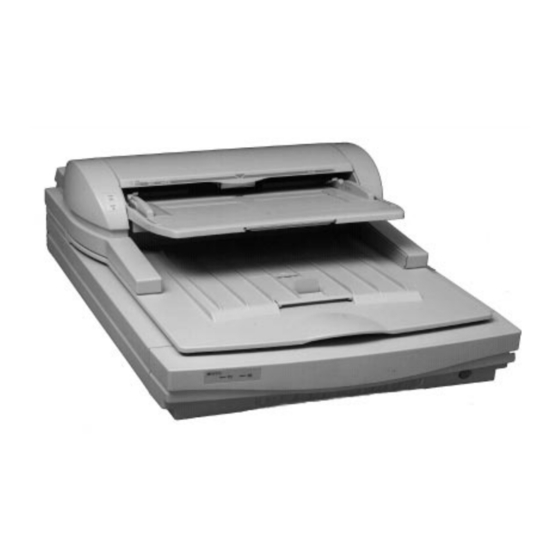
SETTING UP THE SCANNER SETTING UP THE SCANNER GENERAL GUIDE The following illustrations show the names of the various components that make up the scanner. Front View Document Feeder Closed Document table Output table Document stopper Scanner indicators Power switch Front View Document Feeder Open White sheet... -
Page 16: Rear View
SETTING UP THE SCANNER Rear View SCSI Power cord socket RS-232C connector Rotary switch connectors DIP switches Service switch CAUTION: Do not touch the service switch. This switch is provided for use by service personnel only. Scanner Indicators Power on Machine busy Document in place Error... -
Page 17: Checking The Parts
SETTING UP THE SCANNER CHECKING THE PARTS Make sure that you have all the parts shown below in your packing box. Parts list Name Q’ty Name Q’ty Scanner Power cord Terminator driver soft & manual (ISIS) 1set Operator’s manual Scanner Power cord driver soft &... -
Page 18: Scanner Location
SETTING UP THE SCANNER SCANNER LOCATION Before actually setting up the scanner, take a few minutes to consider where you plan to use it. Remember the following points when doing this. Set up the scanner in an easily accessible area with temperatures between 50 and 90 degrees Fahrenheit (10 to 32 degrees Celsius) with a relative humidity of... -
Page 19: Connecting To The Host
SETTING UP THE SCANNER CONNECTING TO THE HOST Use the following procedure to connect the scanner to a host computer using a SCSI cable. Note the following important points when making SCSI cable connections. Turn all devices being connected before making any connections. The use of cables other than the specified shielded cables or their equivalents will invalidate your scanner’s certification and can cause interference levels that exceed the limits established for this equipment. - Page 20 SETTING UP THE SCANNER Plug one end of the shielded high density 50-pin SCSI II cable (ANSI-compliant*1) into the SCSI II port located on the back of the scanner. If you do not plan to connect anything to the other port, cap it with a terminator*2.
- Page 21 SETTING UP THE SCANNER *2 Terminators Generally you need to have two terminators at each end of a SCSI chain. If you connect this scanner at the end of a SCSI chain, you should cap the scanner’s unused SCSI port with a terminator. If the scanner is located inside of a SCSI chain that is already terminated, you do not need to terminate the scanner’s other port.
-
Page 22: Setting The Scsi Id
SETTING UP THE SCANNER SETTING THE SCSI ID Each device in a SCSI chain must have its own unique ID. Use the procedure below to set the scanner’s SCSI ID. Note the following important points when setting the scanner’s SCSI ID. No two devices in the SCSI chain can have the same SCSI ID. -
Page 23: Using Two Scanners In The Same Scsi Chain
SETTING UP THE SCANNER USING TWO SCANNERS IN THE SAME SCSI CHAIN Two of these scanners can be included in the same SCSI chain. In such a case, you must make sure to correctly make certain settings in order to avoid conflicts in the chain. -
Page 24: Connecting The Power Cord
SETTING UP THE SCANNER CONNECTING THE POWER CORD Use only the power cord that comes with the scanner to connect it to a power source. Note the following important points when connecting the power cord. Use only the power cord supplied with the scanner. Connect the power cord to the scanner and plug it into a wall outlet before turning on the power switch. -
Page 25: Turning On The Scanner
SETTING UP THE SCANNER TURNING ON THE SCANNER Use the procedure below to turn on scanner power. To turn on the scanner power Check to make sure that the DIP switches on the back of the scanner are set correctly. Note: The setting as shown is one example. -
Page 26: Dip Switch Settings
SETTING UP THE SCANNER DIP SWITCH SETTINGS DIP switches on the back of the scanner can be used to control certain scanner features and functions. The following describes the DIP switch settings that can be made by you. Note: You can change the settings of DIP switches 1, 3, and 4 only. Never change the settings of switches 2, 5, 6, 7, or 8. -
Page 27: To Change Dip Switch Settings
SETTING UP THE SCANNER To change DIP switch settings Turn off the scanner and make the DIP switch settings described above. Turn the scanner back on. 1-13... -
Page 28: Installing The Drivers
SETTING UP THE SCANNER INSTALLING THE DRIVERS You must intall the scanner driver software on the host computer before you can use the scanner. Installing the TWAIN Scanner Driver Follow these steps to install the TWAIN scanner driver on your Windows 3.1, Windows 95, and Windows NT system: Insert the “TWAIN Scanner Driver for Windows”... -
Page 29: Using The Scanner Introduction
USING THE SCANNER USING THE SCANNER INTRODUCTION This chapter describes what you need to know to how to use the scanner. Note that only operation of the scanner’s hardware is covered here. For details about using the scanner’s software driver you need to consult the separate Scanner Driver Manual for ISIS and the Driver Online-help for TWAIN. -
Page 30: Placing Originals On The Scanner
USING THE SCANNER PLACING ORIGINALS ON THE SCANNER You can place your originals on the scanner for scanning in one of two ways: you can place them manually directly onto the glass one at a time (Book Mode), or you can use the document feeder to feed the originals automatically (Document Feeder Mode). -
Page 31: Using The Book Mode
USING THE SCANNER USING THE BOOK MODE With the Book Mode, you place the object you want to scan directly onto the glass. You must use this mode when scanning pages in a book, magazine, or other bound document. You can scan a page that contains figures written in pencil, toner, ink, ball point pen, or anything else that does not stick to the scanner’s glass. - Page 32 USING THE SCANNER Slowly close the document feeder. Execute the scan operation from the host computer. R CAUTION: Take care to avoid strong pressure on or impact to the scanner’s glass while the document feeder is open, otherwise glass is broken and this may cause injury. Also keep your fingers away from the scanner’s hinges to avoid pinching your fingers whenever opening or closing the document feeder.
-
Page 33: Using The Document Feeder Mode
USING THE SCANNER USING THE DOCUMENT FEEDER MODE The Document Feeder Mode lets you automatically feed single-sheet originals from the document feeder for high-speed scanning. The following defines the type of original that can be scanned using the Document Feeder Mode. Any original that does not meet the following specifications must be scanned using the Book Mode. -
Page 34: To Use The Document Feeder
USING THE SCANNER To use the document feeder Fan the stack of originals and even up its four sides. Raise the document stopper. Squeezing the guide lock on the left side of the guide, adjust the document guides so they match the wide of the original. - Page 35 USING THE SCANNER Note: Make sure the top of the stack of originals is not above the top lines marked on the guides. Place the stack of originals onto the document feeder, and slide them into the feeder until the indicator lights.
-
Page 37: Maintenance Overview
MAINTENANCE MAINTENANCE OVERVIEW This chapter tells you everything you need to know about maintenance of your scanner and procedures to take to solve scanner problems. This information helps keep your scanner in good working condition and helps you correct any problems that might occur. -
Page 38: Cleaning The Scanner
MAINTENANCE CLEANING THE SCANNER This section describes the cleaning requirements of your scanner. Remember that keeping scanner components clean is the secret to both good scanning results and long scanner life. Contact Glass, Slit Glass, White Sheet, White Bar Dirty glasses or white sheet and bar adversely affects the quality of your scanned images. -
Page 39: Rollers And Belt
MAINTENANCE Rollers and Belt Feed errors such as jams or multiple feeding indicate that the scanner’s rollers or belt may need cleaning. Open the document feeder cover to inspect the rollers and belt for dirt. If they are dirty, clean them with a damp cloth. Open the document feeder cover. - Page 40 MAINTENANCE After closing the feed roller unit, use a damp soft cloth to clean the two rollers inside the document feeder cover. If feed errors continue to occur after you clean the rollers, it may mean that it’s time to replace the roller set (see the next section). Note: Always clean the feed rollers after scanning documents that smear or contain substances that may be transferred to the rollers.
-
Page 41: Replacing The Roller Set
MAINTENANCE REPLACING THE ROLLER SET Your scanner requires periodic cleaning of the roller set in order to keep originals feeding properly. If feed problems continue to occur even after you clean the roller set, it means that you must replace the roller set with a new one. Contact your dealer for information about purchasing a roller assembly. - Page 42 MAINTENANCE Pull out the black plastic cover next to the large white roller, and then remove the white roller. Note: Take care that you do not damage the nearby mylar guide when removing Roller A. Insert a new white roller into the scanner.
- Page 43 MAINTENANCE Replace the black plastic cover. Install the new feed roller unit into the scanner as shown in the illustration. Double check to make sure that the pins on the end of the shaft that is towards the back of the scanner seat properly into the holes that are provided.
-
Page 45: Troubleshooting Overview
TROUBLESHOOTING TROUBLESHOOTING OVERVIEW This chapter provides information on problems that may occur while using the scanner, as well as the actions you can take to solve the problems. Operational errors are indicated by indicators located on the front of the scanner, above the power switch. -
Page 46: Document Feeder Raised
TROUBLESHOOTING Document Feeder Raised Indicator Color Green Green Green Status This error indicates that the document feeder is raised. Lower the document feeder cover, making sure it goes all the way down. Paper Jam Indicator Color Green Green Green Status Blinking This error indicates that an original is jammed in the document feeder. - Page 47 TROUBLESHOOTING Inspect the original for tears or curling. If it is in good condition, return it to the starting position on the document feeder and restart the scan job. If the original is wrinkled, smooth it out and scan using the Book Mode. Open the document feeder.
-
Page 48: Paper Misfeed
TROUBLESHOOTING Paper Misfeed Indicator Color Green Green Green Status This error indicates that the document feeder could not feed the originals for some reason. Open the document feeder cover and carefully remove the original as shown in the illustration. If the original does not pull out easily, perform step 2. -
Page 49: System Error
TROUBLESHOOTING Return the green release lever to its original position. Inspect the original for tears or curling. If it is in good condition, return it to the starting position on the document feeder and restart the scan job. If the original is wrinkled, smooth it out and scan using the Book Mode. - Page 50 TROUBLESHOOTING The following table shows other possible problems that are not indicated by the indicators, along with the actions you should take to correct them. Condition Action Scanner is not Make sure that the power switch is on. turned on. Make sure that the power cord is properly plugged in to an appropriate power outlet.
-
Page 51: Scanner Specifications Specifications
SCANNER SPECIFICATIONS SCANNER SPECIFICATIONS SPECIFICATIONS This section contains the electrical and hardware specifications for your scanner as well as information on the paper feed capabilities provided by the Automatic Document Feeder (ADF). Electrical and Hardware Specifications Note: All specifications are subject to change without notice. Type: Desktop type scanner Scanning Method:... -
Page 52: Environmental Specifications
SCANNER SPECIFICATIONS Environmental Specifications Temperature: 10 to 32 degrees Celsius Humidity: 20 to 80 percent Air circulation: 30 cubic meters, per person, per hour Clearance: 600 mm (24”) above 30 mm (1”) left and right sides 50 mm (2”) rear... -
Page 53: Interfaces
SCANNER SPECIFICATIONS This section provides information on the shielded high density 50-pin SCSI II cable you use to connect your scanner to your host computer, on the SCSI II Terminator plug you use on your machine, and on the RS-232C interface. It is your responsibility to make sure that you have a SCSI II port available on the host computer and to provide the SCSI II cable. -
Page 54: Scsi Ii Interface
SCANNER SPECIFICATIONS SCSI II Interface The SCSI II connection is a standard SCSI II interface and requires a shielded high density 50-pin SCSI II bus and tag cable with an A Connector and a SCSI II port available on the host computer. The terminator is a standard SCSI II Terminator plug and is provided with the scanner. - Page 55 SCANNER SPECIFICATIONS Code Signal DB<2> Data DB<3> Data DB<4> Data DB<5> Data DB<6> Data DB<7> Data DB<P> Data Signal Ground Signal Ground RESERVED Reserved TERMPWR* Term Power RESERVED Reserved Signal Ground -ATN Attention Signal Ground -BSY Busy -ACK Acknowledge -RST Reset -MSG Message...
-
Page 56: Rs-232 Interface
SCANNER SPECIFICATIONS RS-232C Interface This interface is provided for connection of the optional Operation Panel. It requires a standard RS-232C cross cable (3 meters maximum length) for connection. The scanner side of the cable should have a 25-pin male connector, while the other end of the cable should have a connector that matches the needs of your host computer. -
Page 57: Options
SCANNER SPECIFICATIONS OPTIONS This section describes the options that are available for this scanner. Options include an Image Processing Unit (IPU) and an Operation Panel. The optional Image Processing Unit (IPU) adds the following functionality: Dynamic threshold - the scanned image is automatically converted to line art using the appropriate threshold. -
Page 59: Scanner Features Scanner Functionality
SCANNER FEATURES A. SCANNER FEATURES SCANNER FUNCTIONALITY This appendix contains descriptions and illustrations of the functions and features provided by your scanner, as well as illustrations of how your scanned images will output based on various specifications. Note: The scanner is controlled by the driver software you are using. Some software does not support all of the functions discussed in this appendix. - Page 60 SCANNER FEATURES Function Scanning a selected area of an image using the settings you specify. Usage Enter the settings you want to use, for example, the scan area, scanning composition, resolution, and so forth. Use Scan to scan the image using these parameters. Determine the value of the settings based on the original and the output device (screen, printer, and so forth).
-
Page 61: Scanning Composition
SCANNER FEATURES Scanning composition Function You can scan using one of three compositions: binary, halftone, or multi-value. Binary scanning records only black and white from the original. Halftone scanning records gray shades from the original using a pattern of black and white dots. Multi-value scanning records grays over 16, 64, or 256 levels. -
Page 62: Binary Scanning-Threshold
SCANNER FEATURES Binary Scanning - Threshold Function Binary scanning converts every pixel included in the image to either black or white. When the image contains a gray area, the threshold value determines whether the scanner records the area as black or white. -
Page 63: Dynamic Threshold
SCANNER FEATURES Dynamic threshold The scanned image is converted to binary using an appropriate threshold. The threshold is determined by the scanner using an optional image processing unit. Dynamic threshold Note:Dynamic threshold is available only when the optional Image Processing Unit is installed. -
Page 64: Halftone Scanning
SCANNER FEATURES Halftone scanning Function Creates the illusion of gray scales by simulating shades of gray from patterns of black and white dots. Usage Use halftone scanning when you are scanning an image that has gray shadings (for example, a photograph) when you want to print or display the image on a monochrome device, such as a laser printer. -
Page 65: Multi-Value Scanning
SCANNER FEATURES Multi-value scanning Function Multi-value scanning can record 4, 6, or 8 bits of information for each dot on the image. The 4-bit multi-value data represents 16 different shades of gray, the 6-bit data represents 64 shades of gray, and the 8-bit data represent 256 different shades of gray. Therefore, an 8-bit scan of an image requires eight times more space than a binary (1-bit) scan of the same image. -
Page 66: Area Extraction
SCANNER FEATURES Area extraction Function Extracts a rectangular area from the whole scannable area. Usage Use area extraction when you want to extract a portion of an image. For example, when you want to extract a photograph from a page, define a rectangle over the photograph, as shown below. -
Page 67: Section Area (Multi-Area Settings
SCANNER FEATURES Section area (multi-area settings) Function Within the scan area, you can set separate rectangular areas and define separate scanning modes, such as binary scanning, halftone scanning, or binary filters, for each area. You can specify up to six areas for one scan. -
Page 68: Auto Photo/Letter
SCANNER FEATURES Auto photo/letter Function The auto photo/letter mode detects photograph (halftone) areas and letter (binary) areas of the original so that the binary areas are scanned in the binary mode, and the halftone areas are scanned in the halftone mode. Note: This function is available only when the optional image processing unit is installed in the scanner. -
Page 69: Resolution
SCANNER FEATURES Resolution Function Sets vertical and horizontal resolution independently at 60, 75, and 100 to 800 dots per inch (dpi). The higher the resolution, the finer the detail. However, a high resolution image requires much more memory and processing time than a low resolution image. Note: When the resolution is set at more than 400 dpi, the maximum scanning width is less than 304 mm. -
Page 70: Brightness
SCANNER FEATURES Brightness Function Adjusts the brightness value between 1 and 255. A high brightness setting results in a lighter overall image, while a low brightness setting results in a darker overall image. Usage When scanning a dark image, the darker area may display as deep black, even though it has gray scales. -
Page 71: Gamma Correction
SCANNER FEATURES Gamma correction Function Selects the following gamma correction settings: Normal - emphasizes contrast slightly to improve a scanned image. Sharp - emphasizes contrast to sharpen an image. Smooth - weakens contrast to soften an image. Linear - outputs an image as scanned. User defined - loads user gamma correction curve into the scanner. -
Page 72: Binary Filter
SCANNER FEATURES Binary filter Function You can use the following binary filters for binary scanning: Noise elimination - eliminates independent black or white dots. Smoothing - flattens uneven dots. Thickening black lines - thickens thin lines. Edge extraction - extracts outlines of the image. Usage Use these filters as shown below. -
Page 73: Parameter Download
SCANNER FEATURES Parameter download Function Downloads a gamma curve and a dither pattern to the scanner. You can modify the scanned image with your gamma curve and convert it to binary using your dither pattern. Refer to your software manual for information on how to download these parameters to the scanner. -
Page 75: Glossary Acronyms
GLOSSARY GLOSSARY ACRONYMS This section contains a list of the acronyms you may use while working with the scanner and the scanner documentation. Automatic Document Feeder dots per inch Input/Output Light Emitting Diode Megabyte Personal Computer pages per minute Random Access Memory Read Only Memory SCSI II Small Computer Systems Interface type two. -
Page 76: Terms
GLOSSARY TERMS This section contains a list of the terms you may use while working with the scanner and the scanner documentation. application Software program, or programs used to process information. asynchronous Data communication transmissions that are controlled by start and stop characters, causing the time intervals between the transmission of data blocks to be unequal in length. - Page 77 GLOSSARY Dots per inch. The number of dots that scan in an inch. These are used to form a character or graphic on the scanned page. drivers Software used to provide scanner characteristics. image area Area of the scanned page that can contain graphics or text. initialize Setting all computer system information to the starting or default values.
- Page 78 GLOSSARY raster Graphic created using a pattern of dots. graphics Raster image Processor board (RIP) that builds a raster image that is processor passed to the scanner. rasterization Transformation of an image onto a page using bitmap dots. resolution Number of dots per inch (dpi) or spots per inch (spi). The greater the number of dots or spots per inch, the higher the resolution and the clearer the image.
- Page 80 Part number G4058600A Printed in Japan...