
Related Manuals for Omron JZA24P0BAA


Summary of Contents for Omron JZA24P0BAA
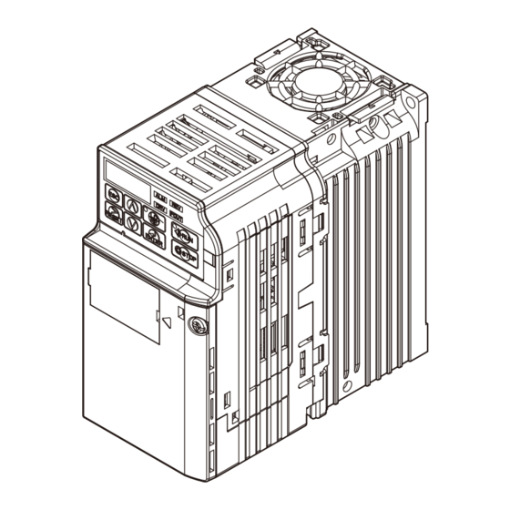
- Page 1 Manual No. I80E-EN2-01 J1000 Compact General Purpose Inverter Model: JZA 200 V Class Three-Phase Input 0.1 to 0.4 kW 200 V Class Single-Phase Input 0.1 to 1.5 kW 400 V Class Three-Phase Input 0.2 to 4.0 kW QUICK START GUIDE...
- Page 3 Compact V/f Control AC Drive J1000 Quick Start Guide Type: JZA Models: 200 V Class, Three-Phase Input: 0.1 to 4.0 kW 200 V Class, Single-Phase Input: 0.1 to 1.5 kW 400 V Class, Three-Phase Input: 0.2 to 4.0 kW Manual No. I80E-EN YE Ref.
-
Page 4: Table Of Contents
J1000 Quick Start Guide 1 Safety Instructions and General Warnings ..4 2 Mechanical Installation ......9 3 Electrical Installation . -
Page 5: Safety Instructions And General Warnings
1 Safety Instructions and General Warnings Safety Instructions and General Warnings Omron Yaskawa Motion Control B.V. (OYMC) supplies component parts for use in a wide variety of industrial applications. The selection and application of OYMC products remain the responsibility of the equipment designer or end user. OYMC accepts no responsibility for the way its products are incorporated into the final system design. - Page 6 1 Safety Instructions and General Warnings NOTICE Indicates a property damage message. Safety Warnings WARNING Electrical Shock Hazard • Do not attempt to modify or alter the drive in any way not explained in this manual. Failure to comply could result in death or serious injury. OYMC is not responsible for any modification of the product made by the user.
- Page 7 1 Safety Instructions and General Warnings WARNING Sudden Movement Hazard • System may start unexpectedly upon application of power, resulting in death or serious injury. Clear all personnel from the drive, motor, and machine area before applying power. Secure covers, couplings, shaft keys, and machine loads before applying power to the drive. Fire Hazard •...
- Page 8 1 Safety Instructions and General Warnings NOTICE Equipment Hazard • Observe proper electrostatic discharge procedures (ESD) when handling the drive and circuit boards. Failure to comply may result in ESD damage to the drive circuitry. • Never connect or disconnect the motor from the drive while the drive is outputting voltage. Improper equipment sequencing could result in damage to the drive.
- Page 9 1 Safety Instructions and General Warnings Precautions for CE Low Voltage Directive Compliance This drive has been tested according to European standard EN61800-5-1: 2007, and it fully complies with the Low Voltage Directive. The following conditions must be met to maintain compliance when combining this drive with other devices: Do not use drives in areas with pollution higher than severity 2 and overvoltage category 3 in accordance with IEC664.
-
Page 10: Mechanical Installation
2 Mechanical Installation Mechanical Installation Upon Receipt Please perform the following tasks after receiving the drive: • Inspect the drive for damage. If the drive appears damaged upon receipt, contact your sup- plier. • Verify receipt of the correct model by checking the information on the nameplate. If you have received the wrong model contact your supplier. - Page 11 2 Mechanical Installation Installation Orientation and Spacing Always install the drive in an upright position. 30mm 30mm 100mm Leave space around the unit for proper cooling as shown in the figure on the right. Note: Several units can be installed closer together than shown in the figure by using “Side-by-Side”...
-
Page 12: Electrical Installation
3 Electrical Installation Electrical Installation The figure below shows the main and control circuit wiring. Terminals marked -,+1,+2,B1,B2 are for connecting an option. Do not wire AC power lines to these terminals. DC reactor Braking Thermal (option) For 1-phase relay resistor (option) power supply use... - Page 13 3 Electrical Installation Wiring Specification Main Circuit Use the fuses and line filters listed up in the table below when wiring the main circuit. Make sure not to exceed the given tightening torque values. EMC Filter Type Main Circuit Terminal Sizes Recom.
- Page 14 3 Electrical Installation EMC Filter Installation This drive has been tested in accordance with European standards EN61800-3:2004. In order to comply to the EMC standards, wire the main circuit as described below. 1. Install an appropriate EMC noise filter to the input side.See the list above or refer to the instruction manual for details.
- Page 15 3 Electrical Installation • Use only circuit breakers that have been designed specifically for drives. • If using a ground fault circuit breaker, make sure that it can detect both DC and high fre- quency current. • If using an input switch is used, make sure that the switch does not operate not more than once every 30 minutes.
- Page 16 3 Electrical Installation Main Circuit Terminals Terminal Type Function Connects line power to the drive. Main circuit power sup- R/L1, S/L2, T/L3 Drives with single-phase 200 V input power use terminals R/L1 ply input and S/L2 only (T/L3 is not used). U/T1, V/T2, W/T3 Drive output Connects to the motor.
-
Page 17: Keypad Operation
4 Keypad Operation Keypad Operation LED Operator and Keys The LED operator is used to program the drive, to start/ stop it, and to display fault information. The LEDs indi- cate the drive status. STOP Keys and Functions Display Name Function Data Display Area Displays the frequency reference, parameter number, etc. - Page 18 4 Keypad Operation Menu Structure and Modes The following illustration explains the operator keypad menu structure. Key operation description Turn the power on (DRV flashes) Forward Selection Reverse Selection<1> Output Frequency Output Current Output Voltage The Monitor Displays are used to read out drive data like terminal Monitor Display status, output frequency, fault...
-
Page 19: Start Up
5 Start Up Start Up Drive Setup Procedure The illustration below shows the basic setup procedure. Each step is explained more detailed on the following pages. START Intstall and wire the drive as explained. Turn the power on. Initialize the drive if necessary using parameter A1-01. Set/check the basic parameters: * b1-01, b1-02 for frequency reference and RUN command source * H1-... - Page 20 5 Start Up Power On Before turning on the power supply, • Make sure all wires are connected properly. • Make sure no screws, loose wire ends or tools are left in the drive. • After turning the power on, the drive mode display should appear and no fault or alarm should be displayed.
- Page 21 5 Start Up Analog Monitor Output (H4- Use the H4- parameters to set up the output value of the analog monitor output and to adjust the output voltage levels. The default monitor value setting is “Output frequency”. Frequency Reference and Acceleration/ Deceleration Times Frequency Reference Setup(b1-01) Set parameter b1-01 according to the frequency reference used.
-
Page 22: Parameter Table
6 Parameter Table Parameter Table This parameter table shows the most impor- Par. Name Description tant parameters. Default settings are bold DC Inj. type. Refer to the instruction manual for a Braking Sets the time of DC Injection Brak- complete list of parameters. Time/DC b2-03 ing at start in units of 0.01 seconds. - Page 23 6 Parameter Table Par. Name Description Par. Name Description 1:2.0 kHz Motor 2:5.0 kHz E2-03 No-Load Magnetizing current in Ampere. Current 3:8.0 kHz Carrier Fre- 4:10.0 kHz Motor Line- C6-02 quency Sets the phase-to-phase motor 5:12.5 kHz E2-05 to-Line Selection resistance in ohms.
- Page 24 6 Parameter Table Par. Name Description Monitor Description Stall Prevention Output Terminal Status 0:Disabled - Motor accelerates at Stall : ON : OFF active acceleration rate and may U1-11 Prevention stall with too heavy load or too 1: Relay Output Reserved Selection (terminal MA-MC closed...
-
Page 25: Troubleshooting
7 Troubleshooting Troubleshooting General Fault and Alarms Faults and alarms indicate problems in the drive or in the machine. An alarm is indicated by a code on the data display and the flashing ALM LED. The drive output is not necessarily switched off. A fault is indicated by a code on the data display and the ALM LED is on. - Page 26 7 Troubleshooting LED Display ALM FLT Cause • Surrounding temperature is too high. Heatsink • The cooling fan has stopped. Overheat • The heatsink is dirty. • The airflow to the heatsink is restricted. • The motor load is too heavy. Motor •...
- Page 27 7 Troubleshooting Operator Programing Errors An Operator Programming Error (OPE) occurs when an inapplicable parameter is set or an individual parameter setting is inappropriate. This monitor will display the parameter that is causing the OPE error. LED Operator Cause Corrective Action Display oPE01 Drive capacity and value set to o2-04 do not...
- Page 28 Revision History The revision dates and numbers of the revised manuals are given on the bottom of the back cover. MANUAL NO. TOEP C710606 28A Published in Japan December 2007 07-11 Revision number Date of original publication Date of publication Date of Publication Rev.