Chapters
Table of Contents

Related Manuals for Omron CIMR-J7AZ - QUICK


Summary of Contents for Omron CIMR-J7AZ - QUICK
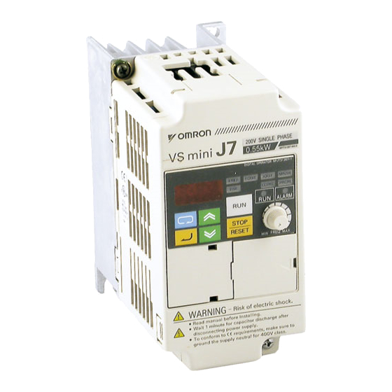
- Page 1 Manual No. I39E-EN-01 VS mini J7 Compact General Purpose Inverter Model: CIMR-J7AZ 200V Class 3-phase 0.1 to 4.0kW 200V Class Single-phase 0.1 to 1.5kW 400V Class 3-phase 0.37 to 4.0kW QUICK MANUAL...
-
Page 3: General Precautions
This manual may be modified when necessary because of improvements to the product, modifications, or changes in specifications. To order a copy of this manual, or if your copy has been damaged or lost , contact your OMRON YASKAWA Motion Control B. V. (Hereinafter called the OYMC) representatives. - Page 4 Additional insulation may be necessary in the end product to conform to CE requirements. · For 400 V class Inverters, make sure to ground the supply neutral to conform to CE requirements. · For conformance to EMC directives, refer to section 3 in this document.
-
Page 5: Warning Display
Warning Display Japanese/French Warning Display An English warning display is on the front panel of the inverter. If you need Japanese or French warning display, use the stickers at the back of this manual. Place it over the English warning display. -
Page 6: Checking The Name Plate
· Mount the Inverter on nonflammable material (i.e., metal). Failure to observe this caution may result in a fire. · When mounting Inverters in an enclosure, install a fan or other cooling device to keep the intake air temperature below 122°F (50°C) for IP20 (open chassis type), or below 105°F(40°C) for NEMA1 (TYPE1). - Page 7 · For 400V class, make sure to ground the supply neutral. Failure to observe this warning may result in an electric shock or a fire. · If the power supply is turned ON during the FWD(or REV) RUN command is given, the motor will start automatically.
- Page 8 Preautions for wiring Wiring the control circuit terminals Screwdriver blade width Insert the wire into the lower part of the terminal block and connect it tightly with a screwdriver. Wire sheath strip length must be 5.5mm (0.22in).
- Page 9 · Never touch the terminals while current is flowing, even if the Inverter is stopping. Failure to observe this warning may result in an electric shock. · When the fault retry function is selected, stand clear of the Inverter or the load. The Inverter may restart suddenly after stopping.
- Page 10 WARNING · If an alarm is reset with the operation signal ON, the Inverter will restart automatically. Reset an alarm only after verifying that the operation signal is OFF. Failure to observe this warning may result in injury. · When the 3-wire sequence is set, do not make the wiring unless the multi-function input terminal parameter is set.
-
Page 11: Maintenance And Inspection
Confirm that all indicators are OFF before proceeding. If the indicators are not OFF, the capacitors are still charged and can be dangerous. · Do not perform withstand voltage test on any part of the VS mini. -
Page 12: Periodical Inspection
Periodical Inspection Periodically inspect the inverter as described the following table to prevent accidents and to ensure high performance with high-reliability. Location to check Check for Solution Terminals, unit mounting screws, Connection hardware is properly Properly seat and tighten etc. - Page 13 CAUTION · Do not subject the Inverter to halogen gases, such as fluorine, chlorine, bromine, and iodine, at any time even during transportation or installation. Otherwise, the Inverter can be damaged or interior parts burnt.
-
Page 15: Quick Start Guide
VS MINI J7 Quick Start Guide 1. Wiring 2. Control Circuit Terminals 3. Installation 4. Start up and Trial run 5. Quick Parameter List 6. Monitors 7. Faults and Alarms... - Page 16 (2 kΩ 1/4 W min.) Frequency reference common Note 1: Connect single-phase 200 V AC to terminals R/L1 and S/L2 of the J7AZB Note 2: The braking resistor cannot be connected because no braking transistor is incorporated. Ground terminal...
-
Page 17: Control Circuit Terminals
10 V DC AC Analogue Monitor output Common Common for AM use *1 NPN is the setting for these terminals. No external power supply is required. Refer to connections shown below *2 Functions in parentheses are default settings. Selecting Input Method... - Page 18 3. Installation Two 5 dia holes Dimensions (mm) Supply Recommendations Rated Model Voltage J7AZ MCCB (A) Wire (mm²) Three Phase 20P1 200 V AC 20P2 20P4 20P7 21P5 22P2 24P0 Single Phase B0P1 200 V AC B0P2 B0P4 B0P7 B1P5...
- Page 19 Filter J7AZ 3G3JV- 40P2 PFI3005-SE 111 40P4 40P7 PFI3010-SE 111 41P5 42P2 43P0 PFI3020-SE 144 44P0 Installation of noise filter and J7 Shield Shield Cable Cable Control Panel Control Panel Metal Mounting Metal Mounting Schaffner Schaffner Plate Plate RFI Filter...
-
Page 20: Mounting Dimensions
The output frequency of the Inverter can be monitored or set while this indicator is lit. IOUT indicator The output current of the inverter this indicator is lit. MNTR indicator The values set in U01 through U10 are monitored while this indicator is lit. - Page 21 CIMR-J7AZB@@@: Single phase 200 to 240VAC (Wire R/L1 and S/L2) CIMR-J7AZ4@@@: Three phase 380 to 460VAC 1-2 Make sure that the motor output terminals (U/T1, V/T2, W/T3) are connected to the motor. 1-3 Ensure that the control circuit terminals and the control device are wired correctly.
- Page 22 Step 3 – Initializing parameters To initialize the drive parameters to factory defaults, set parameter n01 = 8. This will set the J7 to accept start/stop commands in what in termed “2-wire control”, i.e. 1 wire for a motor forward/stop command, and 1 wire for a motor reverse/stop command.
- Page 23 Step 6 – Set the operation command This is the method for motor run and stop commands (i.e. how the inverter will start and stop the motor). The two basic operations are for the RUN and STOP/RESET keys on the Digital Operator, or for one of multi-function inputs through the control circuit terminals.
- Page 24 Function Reverse/Stop Fault Output External Fault (NO) During Run External Fault (NC) Frequency agree Faul reset Overtorque being monitored (NO) Multi-step speed reference 1 RUN mode Multi-step speed reference 2 Inverter ready *1 Refer to user’s manual for complete list...
- Page 25 In approximately The parameter number will be displayed. Note 1: To cancel the set value, press the Mode Key instead, The parameter number will be displayed. 2: There are parameters that cannot be changed while the Inverter is in operation. Refer to the list of parameters.
- Page 26 6. Monitors The Vs mini J7 allows you to monitor various conditions, such as output current and status of multi- function inputs. This monitoring is performed via the “U” parameters. Key Secuence Indicator Display example Explanation Power On Press the Mode Key repeatedly until the MNTR indicator is lit.
-
Page 27: Faults And Alarms
Overcurrent Check output for short circuit or ground fault. Output current is higher than 250% of The Load is too large, reduce it ore use larger Inverter. inverter rated current. Check motor FLA rating compared to inverter and V/F setting. - Page 29 VS MINI J7 Kurzanleitung 1. Anschlussplan 2. Steuerklemmen 3. Installation 4. Inbetriebnahme und Testlauf 5. Parameterübersicht 6. Überwachungsanzeige 7. Fehler und Alarme...
- Page 30 Externer Frequenzsollwerteingang Frequenzeinsteller (Potentiometer) Frequenzsollwert-Bezugspotenzial (2 kΩ min. 1/4 W) Hinweis 1: 200 V Wechselspannung: Anschluss an die Klemmen R/L1 und S/L2. Hinweis 2: Der Frequenzumrichter verfügt über keinen Bremstransistor, daher kann kein Bremswiderstand angeschlossen werden. Erdungs- klemme Versorgungsspannungseingangsklemmen Anordnung der Steuerklemmen...
- Page 31 Bezugspotenzial für die Klemme AM Überwachungsausgang *1 Werkseinstellung: NPN-Spannungseingänge. Keine externe Spannungsversorgung erforderlich (siehe nachstehende Anschlussdiagramme) *2 Bei den Funktionsangaben in Klammern handelt es sich um die Standardeinstellungen. Auswahl der Eingangspolarität Mithilfe der Schalter SW7 und SW8 oberhalb des Steuerklemmenblocks kann die Eingangspolarität und die Art...
- Page 32 3. Installation Zwei Bohrungen Ø 5 Abmessungen (mm) Zuleitungen Nenn- Modell Leistungs- spannung J7AZ Draht (mm²) schalter (A) Drehstrom 20P1 200 V AC 20P2 20P4 20P7 21P5 22P2 24P0 Wechselstrom B0P1 200 V AC B0P2 B0P4 B0P7 B1P5 Drehstrom 40P2...
- Page 33 Abmessungen Modell Filter J7AZ 3G3JV- 40P2 PFI3005-SE 111 40P4 40P7 PFI3010-SE 111 41P5 42P2 43P0 PFI3020-SE 144 44P0 Installation von Entstörfilter und Frequenzumrichter Kabelschirm Kabelschirm Schaltschrank Schaltschrank Montageplatte Montageplatte Schaffner Schaffner (Metall) (Metall) Drehstrom- Drehstrom- Entstörfilter Entstörfilter Erdungs- Erdungs- flächen flächen...
- Page 34 IOUT-Anzeige Wenn diese Anzeige leuchtet, wird der Ausgangsstrom des Frequenzumrichters angezeigt. MNTR-Anzeige Wenn diese Anzeige leuchtet, können die durch U01 bis U10 bestimmten Betriebsparameterwerte angezeigt werden. F/R-Anzeige Wenn diese Anzeige leuchtet, kann die Drehrichtung ausgewählt werden, die bei Aktivierung des Frequenzumrichters mit der RUN-Taste verwendet...
- Page 35 1-5 Trennen Sie den Motor von der Last. Schritt 2 – Anschließen der Spannungsversorgung und Überprüfen des Anzeigestatus 2-1 Schließen Sie nach Durchführen der Überprüfungen in Schritt 1 die Spannungsversorgung an den Frequenzumrichter an. 2-2 Treten beim Anschließen und Einschalten der Spannungsversorgung keine Fehler auf, zeigt die...
- Page 36 (OL1). Bei korrekter Einstellung dieses Parameters verhindert der Frequenzumrichter das Durchbren- nen des Motors bei Überlastung. Lesen Sie den auf dem Typenschild des Motors angegebenen Nennstrom (A) ab, und stellen Sie den Parameter n32 auf diesen Wert. Das folgende Beispiel zeigt die Einstellung des Werts 1,8 A.
- Page 37 Wert. Schritt 6 – Einstellen der Befehlsquelle Legen Sie fest, wie die Start- und Stoppbefehle gegeben werden. Dies kann wahlweise über die RUN- und die STOP/RESET-Taste oder über entsprechende Signale an Multifunktionseingängen erfolgen. Die Einstellung der Befehlsquelle erfolgt durch Setzen des Parameters n02 auf den entsprechenden Wert: 0: Die RUN- und die STOP/RESET-Taste sind aktiviert.
- Page 38 Blockierschutz bei Verzögerung: 0: Aktiviert 1: Deaktiviert Multifunktionseingänge Multifunktionsausgänge Einstellung Funktion Einstellung Funktion Rückwärts/Stopp Fehlerausgang Externer Fehler (Schließer) In Betrieb Externer Fehler (Öffner) Frequenzübereinstimmung Fehlerrücksetzung Drehmomentüberschreitung wird überwacht (Schließer) Multistep-Drehzahlsollwert 1 RUN-Betriebsart *1 Eine vollständige Liste finden Sie in der Bedienungsanleitung.
- Page 39 Sie einfach stattdessen die Betriebsartentaste. Anschließend wird wieder die Parameternummer angezeigt. 2: Bestimmte Parameter können während des laufenden Frequenzumrichterbetriebs nicht geändert werden (siehe Parameterliste). Wenn Sie versuchen, einen dieser Parameter zu ändern, zeigt die Datenanzeige beim Drücken der Erhöhen- oder Verringern-Taste keine Änderung.
- Page 40 6. Überwachungsanzeige Der Frequenzumrichter VS Mini J7 ermöglicht die kontinuierliche Anzeige bestimmter Betriebspara- meter (z. B. Ausgangsstrom oder Status der Multifunktionseingänge). Diese Überwachung erfolgt mithilfe der „U“-Parameter. Datenanzeige Tastenfolge Anzeige Erläuterung (Beispiel) Spannung EIN Drücken Sie wiederholt die Betriebsartentaste, bis die MNTR- Anzeige leuchtet.
- Page 41 Dem Frequenzumrichter wurde ein Einer der Parameter für die Funktion der Multifunktionseingänge externer Fehler signalisiert. wurde auf 3 oder 4 gesetzt. Dieser Fehlerzustand kann erst nach Aufheben des RUN-Signals gelöscht werden. Sequenzfehler Umschaltung zwischen lokaler und dezentraler Steuerung kann nur...
-
Page 43: Table Of Contents
VARIADOR DE VELOCIDAD J7 Guía rápida 1. Cableado 2. Terminales del circuito de control 3. Instalación 4. Inicio y prueba de funcionamiento 5. Lista rápida de parámetros 6. Monitorización 7. Fallos y alarmas... - Page 44 Común de referencia de frecuencia Nota 1: Conecte la alimentación monofásica de 200 V c.a. a los terminales R/L1 y S/L2 del J7AZB Nota 2: La resistencia de freno no puede conectarse porque no hay incorporado un transistor de freno.
-
Page 45: Terminales Del Circuito De Control
AC Común de salida de monitorización Común para uso de AM analógica *1 La configuración de estos terminales es NPN. No se requiere una fuente de alimentación externa. Consulte las conexiones que se indican a continuación *2 Las funciones entre paréntesis indican la configuración predeterminada. - Page 46 3. Instalación Dos orificios de 5 de diá. Línea y protección Dimensiones (mm) Tensión Modelo recomendada nominal J7AZ MCCB (A) Hilo (mm²) Trifásica de 20P1 200 V c.a. 20P2 20P4 20P7 21P5 22P2 24P0 Monofásica de B0P1 200 V c.a.
- Page 47 40P2 PFI3005-SE 111 40P4 40P7 PFI3010-SE 111 41P5 42P2 43P0 PFI3020-SE 144 44P0 Instalación del filtro de ruido y J7 Cable Cable apantallado apantallado Panel de control Panel de control Placa de mon- Placa de mon- Filtro trifásico Filtro trifásico taje metálica...
-
Page 48: Inicio Y Prueba De Funcionamiento
Display de datos Muestra los elementos de datos pertinentes, como referencia de frecuencia, frecuencia de salida y valores seleccionados de parámetro. Potenciómetro de Selecciona la referencia de frecuencia en un intervalo entre 0 Hz ajuste de frecuencia y la frecuencia máxima. (FREQ) - Page 49 CIMR-J7AZB@@@: Monofásica de 200 a 240 Vc.a. (hilo R/L1 y S/L2) CIMR-J7AZ4@@@: Trifásica de 380 a 460 Vc.a. 1-2 Asegúrese de que los terminales de salida del motor (U/T1, V/T2, W/T3) estén conectados al motor. 1-3 Asegúrese de que los terminales del circuito de control y el dispositivo de control estén cableados correctamente.
- Page 50 De este modo, el J7 quedará configurado para aceptar comandos de inicio/parada en lo que se denomina “control de 2 hilos”. Es decir, un hilo para el comando de marcha directa/parada y el otro para un comando de marcha inversa/parada de un motor.
- Page 51 Es la frecuencia máxima a la que puede funcionar el motor, y permite al J7 controlarlo correctamente. Lea la frecuencia nominal (en Hz) en la placa de referencia del motor, y especifique este valor en los parámetros n09 y n11.
-
Page 52: Lista Rápida De Parámetros
0: operador digital (potenciómetro) 1: referencia de frecuencia 1 (n21) 2: terminal del circuito de control (0 a 10 V) 3: terminal del circuito de control (4 a 20 mA) 4: terminal del circuito de control (0 a 20 mA) 6: comunicaciones (opcional) Frecuencia de salida máxima... - Page 53 Se mostrará número de parámetro. mente 1 s. Nota 1: Para cancelar el valor seleccionado, pulse la tecla Modo. De este modo se visualizará el número del parámetro. 2: Existen parámetros que no pueden modificarse mientras el variador está en funcionamiento.
-
Page 54: Monitorización
6. Monitorización El variador de velocidad J7 permite monitorizar diversas situaciones, como por ejemplo la corriente de salida y el estado de las entradas multifunción. La monitorización se realiza mediante los parámetros “U”. Secuencia de Ejemplo de Indicador Explicación teclas display Alimentación ON... -
Page 55: Fallos Y Alarmas
Una entrada digital multifuncional ha sido configurada como 12 ó 13. baseblock externo. Se ha producido un error de secuencia Se ha aplicado simultáneamente la señal RUN de directa e inversa. (parpadea) *1 Consulte en el manual del usuario la lista completa de códigos de fallos... - Page 57 VS MINI J7 Guide de démarrage rapide 1. Câblage 2. Bornes de circuit de contrôle 3. Installation 4. Démarrage et essai 5. Aperçu de la liste des paramètres 6. Moniteurs 7. Erreurs et alarmes...
- Page 58 (2 kΩ 1/4 W min.) Commun de référence de fréquence Remarque 1 : Connectez le monophasé 200 Vc.a. aux bornes R/L1 et S/L2 du J7AZB Remarque 2 : La résistance de freinage ne peut être connectée car aucun transistor de freinage n'est incorporé. Connecteur terre Bornes d'entrée du...
- Page 59 Commun de sortie moniteur Commun pour l’utilisation AM analogique *1 NPN est le paramètre de ces bornes. Aucune alimentation externe n’est nécessaire. Consultez les connexions illus- trées ci-après *2 Les fonctions entre parenthèses sont les paramètres par défaut. Choix de la méthode d'entrée Les commutateurs SW7 et SW8, tous deux situés au-dessus des...
- Page 60 3. Installation Deux trous de 5 de diamètre Dimensions (mm) Conseil d’alimentation Tension Modèle nominale J7AZ MCCB (A) Câble (mm²) Triphasé 20P1 200 Vc.a. 20P2 20P4 20P7 21P5 22P2 24P0 Monophasé B0P1 200 Vc.a. B0P2 B0P4 B0P7 B1P5 Triphasé 40P2 400 Vc.a.
- Page 61 J7AZ 3G3JV- 40P2 PFI3005-SE 111 40P4 40P7 PFI3010-SE 111 41P5 42P2 43P0 PFI3020-SE 144 44P0 Installation du filtre d’entrée et J7 Câble Câble blindé blindé Panneau de commande Panneau de commande Plaque de Plaque de Filtre Filtre montage en montage en...
- Page 62 Le courant de sortie du variateur lorsque ce voyant est allumé. Voyant MNTR Les valeurs définies dans U01 à U10 sont surveillées quand ce voyant est allumé. Voyant F/R Le sens de rotation peut être sélectionné quand ce voyant est allumé pendant le fonctionnement du variateur via la touche RUN...
- Page 63 CIMR-J7AZB@@@: Monophasé 200 à 240 Vc.a. (Câble R/L1 et S/L2) CIMR-J7AZ4@@@: Triphasé 380 à 460 Vc.a. 1-2 Veillez à ce que les bornes de sortie du moteur (U/T1, V/T2, W/T3) soient correctement connec- tées au moteur. 1-3 Veillez à ce que la borne du circuit de contrôle et l'appareil de contrôle soient correctement câblés.
- Page 64 = 8. Le J7 acceptera ainsi les commandes marche/arrêt pour ce que nous avons appelé le « contrôle à 2 câbles », c-à-d. 1 câble pour la commande marche/arrêt d’un moteur et 1 câble pour la commande inversion/arrêt d’un moteur.
- Page 65 Etape6 – Définition de la commande de fonctionnement Il s’agit de la méthode de commande de marche et d’arrêt du moteur (c-à-d la manière dont le varia- teur démarrera et arrêtera le moteur). Les deux opérations de base sont pour les touches RUN et STOP/RESET de l’opérateur numérique ou pour l’une des entrées multifonctions via les bornes du cir-...
- Page 66 0: Opérateur numérique (potentiomètre) 1: Référence de fréquence 1 (n21) 2: Borne du circuit de contrôle (0 à 10 V) 3: Borne du circuit de contrôle (4 à 20 mA) 4: Borne du circuit de contrôle (0 à 20 mA) 6: Communication (option) Fréquence de sortie maximale...
- Page 67 (cfr remarque 1) Environ en 1s. Le chiffre du paramètre s'affiche. Remarque 1 : Pour annuler la valeur définie, appuyez sur la touche Mode. Le numéro du paramètre s’affichera. 2 : Certains paramètres ne peuvent pas être modifiés pendant que le variateur fonctionne.
-
Page 68: Moniteurs
6. Moniteurs Le Vs mini J7 vous permet de surveiller plusieurs situations telles que le courant de sortie et le statut des entrées multifonctions. Cette surveillance est possible grâce aux paramètres « U ». Exemple Séquence clé Voyant Explication d’affichage Sous tension Appuyez plusieurs fois sur la touche Mode jusqu’à... -
Page 69: Erreurs Et Alarmes
Cause possible et solution l’erreur Surintensité Vérifiez s’il n’y a pas un court-circuit ou une erreur de terre à la Le courant de sortie est supérieur à sortie. La charge est trop importante. Diminuez-la ou utilisez un 250 % du courant nominal du plus grand variateur. - Page 71 VS MINI J7 Guida di avvio rapido 1. Cablaggio 2. Terminali circuito di controllo 3. Installazione 4. Avvio e collaudo 5. Elenco dei parametri principali 6. Funzioni di monitoraggio 7. Errori e allarmi...
- Page 72 Comune frequenza di riferimento Nota 1: Collegare il circuito monofase 200 V c.a. ai terminali R/L1 e S/L2 del J7AZB Nota 2: Non è possibile collegare la resistenza di frenatura perché non è integrato alcun transistor di frenatura. Terminale di...
-
Page 73: Terminali Circuito Di Controllo
10 V c.c. AC Comune uscita analogica di monitor Comune per l'utilizzo di AM *1 L'impostazione di questi terminali è NPN. Non è necessaria alcuna alimentazione esterna. Fare riferimento ai collegamenti mostrati qui di seguito *2 Le funzioni tra parentesi sono impostazioni predefinite. - Page 74 3. Installazione Due fori diametro 5 Raccomandazioni per Dimensioni (mm) Tensione Modello l'alimentazione nominale J7AZ MCCB (A) Filo (mm²) Trifase 20P1 200 V c.a. 20P2 20P4 20P7 21P5 22P2 24P0 Monofase B0P1 200 V c.a. B0P2 B0P4 B0P7 B1P5 Trifase 40P2 400 V c.a.
- Page 75 J7AZ 3G3JV- 40P2 PFI3005-E 40P4 40P7 PFI3010-E 41P5 42P2 43P0 PFI3020-E 44P0 Installazione del filtro antidisturbo e del J7 Cavo Cavo schermato schermato Pannello di comando Pannello di comando Piastra metallica Piastra metallica Trifase con Trifase con di montaggio di montaggio...
-
Page 76: Avvio E Collaudo
Quando questa spia è accesa, è possibile monitorare o impostare la frequenza di uscita dell'inverter. Spia IOUT Quando questa spia è accesa, è possibile monitorare la corrente di uscita dell'inverter. Spia MNTR Quando questa spia è accesa, vengono monitorati i valori impostati nei parametri U01 ... - Page 77 CIMR-J7AZB@@@: Monofase tra 200 e 240V c.a. (Filo R/L1 e S/L2) CIMR-J7AZ2@@@: Trifase tra 380 e 460V c.a. 1-2 Verificare che i terminali di uscita del motore (U/T1, V/T2, W/T3) siano collegati al motore. 1-3 Verificare che i terminali del circuito di controllo e il dispositivo di controllo siano collegati correttamente.
- Page 78 Per inizializzare i parametri secondo le impostazioni di fabbrica, occorre impostare il parametro n01 = 8. In tal modo, il J7 accetterà i comandi di avvio/arresto nel cosiddetto "controllo a 2 fili", cioè 1 filo per il comando marcia avanti/arresto e 1 filo per il comando marcia indietro/arresto.
- Page 79 Il diagramma riportato qui di seguito illustra come collegare un interruttore per avviare e arrestare il motore in marcia avanti nel "controllo a 2 fili". Impostare il parametro n02=1. Per abilitare un interruttore a parte per la marcia indietro sul terminale di controllo S2, impostare il parametro n36=2 (è...
-
Page 80: Elenco Dei Parametri Principali
Uscita d'errore Errore esterno (NA) Durante la marcia Errore esterno (NC) Raggiungimento frequenza di riferimento Sblocco errore Monitoraggio superamento del momento di rotazione (NA) Multivelocità di riferimento 1 Modalità RUN *1 Per conoscere l'elenco completo, fare riferimento al manuale per l'utente... - Page 81 Il numero del parametro verrà visualizzato. mente in 1s. Nota 1: Se invece si desidera cancellare il valore impostato, premere il tasto di selezione modalità. Verrà visualizzato il numero del parametro. 2: Alcuni parametri non possono essere modificati quando l'inverter è in funzione. Fare riferimento all'elenco dei parametri.
-
Page 82: Funzioni Di Monitoraggio
6. Funzioni di monitoraggio Il J7 permette di monitorare varie condizioni, quali la corrente di uscita e lo stato degli ingressi multifunzione. Tale monitoraggio viene effettuato mediante i parametri a "U". Esempio di Sequenza di tasti Spia Spiegazione visualizzazione Accensione Premere ripetutamente il tasto di selezione modalità... -
Page 83: Errori E Allarmi
Un ingresso digitale multifunzione è stato impostato a 12 o 13. blocco delle basi esterno. Si è verificata una sequenza di I segnali di marcia avanti e indietro sono stati attivati contemporanea- (lampeggiante) errore mente. *1 Per conoscere l'elenco completo dei codici di errore, fare riferimento al manuale per l'utente... - Page 85 VS MINI J7 Breve Guia de Introdução 1. Cablagem 2. Terminais do circuito de controlo 3. Instalação 4. Arranque e funcionamento experimental 5. Breve lista de parâmetros 6. Monitores 7. Falhas e alarmes...
- Page 86 (2 kΩ 1/4 W min.) Comum de referência de frequência Nota 1: Ligue a tensão monofásica de 200 V CA aos terminais R/L1 e S/L2 de J7AZB Nota 2: Não é possível ligar a resistência de frenagem, uma vez que não existe qualquer transístor de frenagem incorporado.
- Page 87 10 V CC AC Comum da saída analógica Comum para utilização de AM *1 A definição para estes terminais é NPN. Não é necessária qualquer fonte de alimentação externa. Consulte as ligações mostradas abaixo. *2 As funções entre parênteses constituem as predefinições.
- Page 88 3. Instalação Dois orifícios de 5 dia Recomendações de Dimensões (mm) Tensão Modelo alimentação nominal J7AZ MCCB (A) Fio (mm²) Trifásica 20P1 200 V CA 20P2 20P4 20P7 21P5 22P2 24P0 Monofásica B0P1 200 V CA B0P2 B0P4 B0P7 B1P5 Trifásica...
- Page 89 3G3JV- 40P2 PFI3005-SE 111 40P4 40P7 PFI3010-SE 111 41P5 42P2 43P0 PFI3020-SE 144 44P0 Instalação do filtro de ruído e J7 Cabo Cabo blindado blindado Painel de controlo Painel de controlo Placa de fixação Placa de fixação Filtro Filtro de metal...
- Page 90 Apresenta itens de dados relevantes, tais como a frequência ção de dados de referência, a frequência de saída e valores de parâmetros definidos. Regulador de FREQ Define a frequência de referência num intervalo entre Ohz e a frequência máxima. Indicador FREF É...
- Page 91 CIMR-J7AZ4@@@: Trifásica de 380 a 460VCA 1-2 Certifique-se de que os terminais de saída do motor (U/T1, V/T2, W/T3) estão ligados ao motor. 1-3 Certifique-se de que os terminais do circuito de controlo e o dispositivo de controlo estão ligados correctamente.
- Page 92 Para inicializar os parâmetros para os predefinidos de fábrica, defina o parâmetro n01 = 8. Este pro- cedimento parametriza o J7 para aceitar os comandos de arranque/paragem conhecidos por “con- trolo a 2 fios”, ou seja, 1 fio para o comando directo/paragem do motor e um fio para o comando inverso/paragem do motor.
- Page 93 Passo 6 – Definir o comando de operação Trata-se do método de comandos para arranque e paragem do motor (ou seja, o modo como o varia- dor arranca e pára o motor). As duas operações básicas são executadas utilizando as teclas RUN e STOP/RESET na Consola digital ou utilizando umas das entradas multifunções através dos terminais...
- Page 94 Saída de falha Falha externa (NO) Durante o funcionamento Falha externa (NC) Frequência coincidente Reset de falha BMonitorização de sobrebinário (NO) Velocidade de referência multi- step 1 Modo RUN *1 Consulte o manual de utilizador para obter a lista completa...
- Page 95 O número do parâmetro é apresentado. mente 1s. Nota 1: Para cancelar o valor definido, prima, em alternativa, a tecla de modo. O número do parâmetro é apresentado. 2: Não é possível alterar determinados parâmetros quando o Variador está em funcionamento.
- Page 96 6. Monitores O VS mini J7 permite monitorizar várias condições, tais como a corrente de saída e o estado das entradas multifunções. Esta monitorização é efectuada através dos parâmetros “U”. Sequência Indicador Exemplo de visor Explicação de teclas Ligado Prima a tecla de modo repetidamente até que o indicador MNTR fique iluminado.
- Page 97 Verifique a cablagem do terminal de controlo. Foi definida uma entra- Deu entrada uma falha externa. da digital multifunções para 3 ou 4. É necessário que o sinal de fun- cionamento seja removido antes do reset desta falha. Erro de sequência É...
- Page 99 VS MINI J7 Инструкция по быстрому запуску 1. Подключение цепей 2. Клеммы схемы управления 3. Монтаж 4. Пробный запуск 5. Список основных параметров 6. Контролируемые параметры 7. Коды неисправностей...
- Page 100 1. Подключение цепей 3G3JV PFI @...
- Page 101 (Выходная частота) при 0 … 10 В= AC Общая цепь выхода контроля Общая цепь выхода AM *1 Для этих клемм выбран тип NPN. Внешний источник питания не требуется. Схемы подключения показаны ниже. *2 В скобках приведены значения, принимаемые по умолчанию.
- Page 102 B0P2 B0P4 B0P7 B1P5 400 В~ 40P2 3-фазное 40P4 40P7 41P5 42P2 43P0 44P0 Примечание: МССВ = Автоматический выключатель в литом корпусе. Технические характеристики фильтра подавления помех Размеры Модель Фильтр J7AZ 3G3JV- 20P1 PFI2010-SE 82 20P2 20P4 20P7 21P5 PFI2020-SE 111...
- Page 103 Размеры Модель Фильтр J7AZ 3G3JV- 40P2 PFI3005-SE 111 40P4 40P7 PFI3010-SE 111 41P5 42P2 43P0 PFI3020-SE 144 44P0 Монтаж фильтра подавления помех и инвертора J7 CIMR-J7@@@@20P1 ... 24P0 CIMR-J7@@@@B0P1 ... B4P0 CIMR-J7@@@@40P2 ... 44P0...
- Page 104 Информационный Отображение значений соответствующих параметров, например, дисплей опорной частоты, выходной частоты и настраиваемых параметров. Ручка регулировки Настройка значения опорной частоты в диапазоне от 0 Гц до FREQ максимального значения частоты. Индикатор FREF Когда светится этот индикатор, можно контролировать или настраивать опорную частоту.
- Page 105 CIMR-J7AZB@@@: 200 … 240 В~, 1-фазное (на клеммы R/L1 и S/L2) CIMR-J7AZ4@@@: 380 … 460 В~, 3-фазное 1-2 Убедитесь в том, что к выходным силовым клеммам (U/T1, V/T2, W/T3) подключен двигатель. 1-3 Проверьте цепи, подключенные к клеммам схемы управления, и цепи управляющего...
- Page 106 Шаг 3 – Инициализация параметров Чтобы инициализировать параметры привода (вернуть заводские значения), следует выбрать параметр n01 = 8. В результате инвертор J7 перейдет в так называемый "2-проводный" режим управления. В этом режиме для подачи команд "Ход"/"Стоп" используются два сигнала (два...
- Page 107 значение номинальной частоты (в Гц), указанное на паспортной табличке двигателя. Шаг 6 – Задайте способ подачи команд Выберите способ подачи команд на запуск и останов двигателя (т.е., как инвертор будет запускать и останавливать двигатель). Предусмотрено два основных способа управления: с...
- Page 108 выходного тока инвертора n36 - n39 Многофункциональный вход (S2 -S5) 0 ... 35 Многофункциональный выход (МА-MB-MC) 0 ... 18 Многофункциональный аналоговый выход (AM-AC): 0: Выходная частота (10В/макс. частота) 1: Выходной ток (10В/Номинальный ток инвертора) *1 Полный список приведен в Руководстве по эксплуатации...
- Page 109 Команда 3 выбора предустановленной Пониженное напряжение скорости (частоты) Команда "Толчковый ход" Функции аналоговых выходов Внешний сигнал блокировки выхода Значение Функция (нормально-разомкнутая цепь) Внешний сигнал блокировки выхода Выходная частота (нормально-замкнутая цепь) Выбор локального/дистанционного Выходной ток управления *1 Полный список приведен в Руководстве по эксплуатации...
- Page 110 значение. Индикатор перестанет мигать (см. прим. 1) Приблиз. через 1 с Будет отображен номер параметра. Примечание 1: Чтобы отменить введенное значение, нажмите вместо клавиши "Ввод" клавишу "Режим". Будет отображен номер параметра. 2: Некоторые параметры нельзя изменить, когда инвертор находится в режиме...
- Page 111 параметра Опорная частота (FREF) Гц Контроль значения опорной частоты (как и при использовании FREF) Выходная частота (FOUT) Гц Контроль значения выходной частоты (как и при использовании FOUT) Выходной ток (IOUT) Контроль значения выходного тока (как и при использовании IOUT) Выходное напряжение...
- Page 112 Слишком инерционная нагрузка, двигатель входит в режим Превышен допустимый уровень регенерации. Увеличьте время торможения (n020 или n022). напряжения в шине постоянного Подсоедините внешний тормозной резистор и выберите n092 = 1. тока (уровень обнаружения Проверьте тормозной резистор и его цепи. повышенного напряжения).
- Page 113 Проверьте цепи клемм схемы управления. (мигает) выхода Для многофункционального дискретного входа выбрана Подана внешняя команда функция 12 или 13. блокировки выхода. Ошибка управления Одновременно поданы сигналы "Ход вперед" и "Ход назад". (мигает) *1 Полный список кодов ошибок содержится в Руководстве по эксплуатации...
- Page 116 YASKAWA In the event that the end user of this product is to be the military and said product is to be employed in any weapons sxstems or the manufacture thereof, the export will fall under the relevand regulations as stipulated in the Foreign Exchange and Foreign Trade Regulations.