Omron SYSDRIVE 3G3EV SERIES User Manual
Sysmac bus model compact low-noise inverter
Hide thumbs
Also See for SYSDRIVE 3G3EV SERIES:
- User manual (88 pages) ,
- User manual (119 pages) ,
- User manual (90 pages)
Table of Contents
Advertisement
Advertisement
Table of Contents

Related Manuals for Omron SYSDRIVE 3G3EV SERIES


Summary of Contents for Omron SYSDRIVE 3G3EV SERIES
- Page 1 USER’S MANUAL SYSDRIVE 3G3EV SERIES (SYSMAC BUS Model) Compact Low-noise Inverter...
- Page 2 You should assume that anything not described in this manual is not possible. 2. Although care has been given in documenting the product, please contact your OMRON representative if you have any suggestions on improving this manual. 3. The product contains potentially dangerous parts under the cover. Do not attempt to open the cover under any circumstances.
-
Page 6: Items To Be Checked When Unpacking
Chapter 1 1-1 Items to be Checked when Unpacking Checking the Product On delivery, always check that the delivered product is the SYSDRIVE 3G3EV Inverter that you ordered. Should you find any problems with the product, immediately contact your nearest local sales representative. -
Page 7: Checking Accessories
Chapter 1 Checking Accessories Note that this manual is the only accessory provided with the 3G3EV (SYSMAC BUS Model). Set screws and other necessary parts must be prepared by customers. 1-2 Precautions To ensure safe operation of the 3G3EV, note the following items: Always Hold the Heat Sink During Removal. - Page 8 Chapter 1 Do Not Modify Wiring or Check Signals When the Main Circuit is On. Always turn the main circuit off before modifying wiring or checking signals. Touching terminals while the main circuit is on may cause an electrical shock and dam- age the equipment.
-
Page 10: Easy To Use
Chapter 2 2-1 Features Easy to Use Basic Constants Displayed On Indicators Constants for basic operations such as frequency setting and acceleration/deceleration time setting are displayed on dedicated indicators. Therefore, constant numbers can be confirmed easily. Easy to Install Very Small and Lightweight The 3G3EV Inverter is approximately half the size of our Low-noise General-purpose Inverters in terms of volume and weight percentage. -
Page 11: Low Noise
Chapter 2 Easy to Wire Using Two-conductor Cables to Minimize Wiring Two-conductor cables (VCTF) enable the Inverter to be connected a higher-level PC. Easy Wiring without Having to Open the Front Cover This Inverter can be wired just by opening the terminal block cover. Separate Input and Output Terminal Blocks Power input terminals are located in the upper section, while motor output terminals are in the lower section. -
Page 12: Component Names
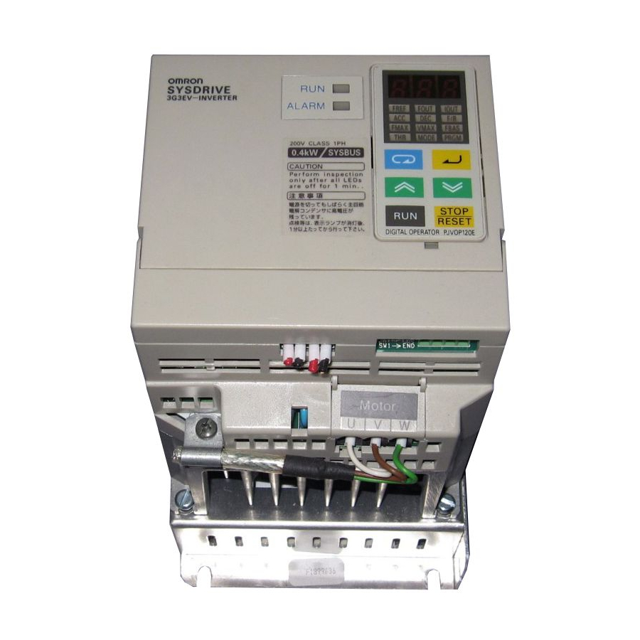
Chapter 2 2-2 Component Names Main Unit Main Circuit Terminals (Input) Power input Braking resistor terminals connection terminals L1 N/L2 L3 B1 B2 Run indicator Digital Operator Alarm indicator Transmission indicator End unit setting switch Transmission Control circuit terminals terminals Ground terminal Motor output terminals... -
Page 13: Digital Operator
Chapter 2 Digital Operator Data display section Monitor item indicators In-service item indicators (green indicators) Display These items can be monitored or set even section during operation. Stopped item indicators (red indicators) These items can be set only when the Inverter is stopped. -
Page 15: Installation
Chapter 3 3-1 Installation 3-1-1 Outside/Mounting Dimensions Note All dimensions are in millimeters. 3G3EV-A2001R to 3G3EV-A2004R (0.1 to 0.4 kW): Three-phase 200-VAC Input 3G3EV-AB001R to 3G3EV-AB002R (0.1 to 0.2 kW): Single/Three-phase 200-VAC Input 4.5 dia. Note 1. For the 3G3EV-A2001R, 3G3EV-A2002R, and 3G3EV-AB001R, a U-shaped notch (4.5 mm wide) is provided instead of the upper mounting hole (4.5 mm in diameter). - Page 16 Chapter 3 Three-phase 200-VAC Input Model 3G3EV Output Weight model (kg) A2001R 0.1 kW Approx. A2002R 0.2 kW Approx. A2004R 0.4 kW Approx. Single/Three-phase 200-VAC Input Model 3G3EV Output Weight model (kg) AB001R 0.1 kW Approx. AB002R 0.2 kW Approx. 3G3EV-A2007R to 3G3EV-A2015R (0.75 to 1.5 kW): Three-phase 200-VAC Input 3G3EV-AB004R to 3G3EV-AB007R (0.4 to 0.75 kW):...
-
Page 17: Installation Conditions
Chapter 3 Three-phase 200-VAC Input Model 3G3EV Output Weight model (kg) A2007R 0.75 kW Approx. 1.3 A2015R 1.5 kW Approx. 1.5 Single/Three-phase 200-VAC Input Model 3G3EV Output Weight model (kg) AB004R 0.4 kW Approx. 1.3 AB007R 0.75 kW Approx. 1.3 3-1-2 Installation Conditions Installation Site Install the Inverter under the following conditions:... -
Page 18: Ambient Temperature Control
Chapter 3 Ambient Temperature Control To enhance operation reliability, the Inverter should be installed in an environment free from extreme temperature rises. If the Inverter is installed in an enclosed environment such as a box, use a cooling fan or air conditioner to maintain the internal air temperature below 50 C. The surface temperature of the Inverter may reach 30 C higher than the ambient tem- perature. -
Page 19: Terminal Blocks
Chapter 3 3-2 Wiring 3-2-1 Terminal Blocks Name of Each Terminal Block Main Circuit Terminals (Input) Power input Braking resistor terminals connection terminals Transmission Control circuit terminals terminals Ground Motor output terminals terminal Main Circuit Terminals (Output) Note This diagram shows an Inverter with all terminal block covers removed. -
Page 20: Main Circuit Terminals
Chapter 3 Main Circuit Terminals Input Terminals (Top Section) Terminal Name and description symbol Power input terminals N/L2 Three-phase, 200 to 230 VAC, 50/60 Hz input terminals. If a 3G3EV-AB R is to be used in single-phase input mode, single-phase 200 to 240 VAC power with a frequency of 50/60 Hz must be input between terminals R and S. -
Page 21: Control Circuit Terminals
Chapter 3 Control Circuit Terminals Input Terminals Terminal Name and description Interface symbol Multi-function input (see notes 1 and 2) Multi-function input common Input common for S1 24 VDC, 8mA Note 1. Constant no. 06 (n06) is used to set this function. This constant is factory-set to “fault reset.”... -
Page 22: Standard Connection Diagram
Chapter 3 Standard Connection Diagram Braking resistor (option) Power supply: Three-phase, 200 to 230 VAC, 50/60 Hz N/L2 Molded-case circuit breaker (MCCB) Multi-function input 1 Multi-function output 1 Multi-function input common Multi-function output common 48 VDC, 50 mA Remote I/O (one input channel Remote I/O Master Unit and one output channel) -
Page 23: Wiring On The Input Side Of Main Circuit
Chapter 3 If the cable is long and may cause voltage drops, increase the wire size according to the cable length. Model Terminal Terminal screw Wire size Molded-case symbol circuit breaker capacity (A) 3G3EV-A2001R R S T B1 B2 M3.5 0.75 to 2 3G3EV-AB001R U V W 3G3EV-A2002R R S T B1 B2... - Page 24 Chapter 3 Installing a Magnetic Contactor This Inverter can be used without a magnetic contactor (MC) on the power supply side. If the power supply for the main circuit is to be shut off because of the sequence, a mag- netic contactor can be used instead of a molded-case circuit breaker.
-
Page 25: Wiring On The Output Side Of Main Circuit
Chapter 3 Installing a Noise Filter on the Power Supply Side Install a noise filter to eliminate noise transmitted between the power line and the Inverter. Wiring Example 1 Power 3G3IV-PHF 3G3EV supply Noise filter SYSMAC, etc. Other controllers Note Use a special-purpose noise filter for Inverters. Wiring Example 2 Power 3G3EV... - Page 26 Chapter 3 Never Connect Power Supply to Output Terminals Caution Never connect a power supply to output terminals U, V, and W. If voltage is applied to the output terminals, the internal mechanism of the Inverter will be damaged. Never Short or Ground the Output Terminals Caution If the output terminals are touched with bare hands or the output wires come into contact with the Inverter casing, an electric shock or grounding will occur.
- Page 27 Chapter 3 Induction Noise: Electromagnetic induction generates noise on the signal line, causing the controller to malfunction. Radio Noise: Electromagnetic waves from the Inverter and cables cause the broadcasting radio receiver to make noise. How to Prevent Induction Noise As described above, a noise filter can be used to prevent induction noise from being generated on the output side.
-
Page 28: Ground Wiring
Chapter 3 Cable Length between Inverter and Motor If the cable between the Inverter and the motor is long, the high-frequency leakage cur- rent will increase, causing the Inverter output current to increase as well. This may affect peripheral devices. To prevent this, adjust the carrier frequency (set in n37) as shown in the table below. -
Page 29: Wiring Control Circuit Terminals
Chapter 3 Note Minimize the total length (5 m or less) between the ground electrode and the ground terminal, and also use a thick wire (1.25 m or more). Leakage current flows through the Inverter. Therefore, if the distance between the ground elec- trode and the ground terminal is too long, potential on the ground terminal of the Inverter will become unstable. - Page 30 Chapter 3 Always separate the control signal line from the main circuit cables and other power cables. Thin-slotted screwdriver Control circuit terminal block Length of stripped portion: Approx. 5.5 mm Do not solder this portion. (Otherwise, faulty contact may result.) Wire 3-2-4 Wiring Transmission Terminals Wire the transmission terminals (+R and --R) as described below.
-
Page 31: Wiring Method
Chapter 3 Wiring Method The wiring method is the same as for sequence input/output terminals, described pre- viously. Always separate the transmission cables from the main circuit cables and other power cables. Always connect the positive terminal to the positive terminal and the negative terminal to the negative terminal. - Page 32 Chapter 3 Example of Connecting Remote I/O Slave Units Connect the Remote I/O Master Unit (C500-RM201 or C200H-RM201) to Remote I/O Slave Units (devices) as described below. Master Unit Slave Unit (device) Connect the Remote I/O Master Unit first, then continue wiring in order. Do not connect a positive terminal to a negative terminal.
-
Page 33: Setting The Terminator
Chapter 3 3-2-5 Setting the Terminator The Remote I/O Unit at the end of the system must be set as the terminator. Otherwise, all Remote I/O Units cannot operate. This section describes how to set the 3G3EV-A R as a terminator. Setting the Terminator Open the terminal block cover in the lower part of the Inverter. -
Page 35: Preparation Procedure
Chapter 4 4-1 Preparation Procedure 1. Installation: Install the Inverter according to installation conditions. Check that all the installation conditions are met. 2. Wiring: Connect the Inverter to power supply and peripheral devices. Select peripheral devices that meet the specifications, and wire them correctly. Set and end unit as necessary. - Page 36 Chapter 4 c) n31 (electronic thermal reference current) d) n11 (reference frequency) Test Run: Check motor operation. Use the Digital Operator to check motor operation. Perform a no-load test run and an actual loading test run to check the direction of motor rotation, speed, and output cur- rent.
-
Page 37: Using The Digital Operator
Chapter 4 4-2 Using the Digital Operator 4-2-1 Name and Function of Each Component Name of Each Component Data display section Monitor item indicators Display In-service item indicators (green indicators) section These items can be monitored or set even during operation. Stopped item indicators (red indicators) These items can be set only when the Inverter is stopped. -
Page 38: Function Of Each Component
Chapter 4 Function of Each Component Display Sections Data display section Reference frequency values, output frequency values, output current values, constant settings, and error codes are displayed. Monitor item indicators When this indicator is lit, an output frequency value (Hz) is displayed in the data display section. -
Page 39: Outline Of Operation
Chapter 4 4-2-2 Outline of Operation Switching Data Display during Operation Press the Mode Key to switch data display. During operation, only the items in the in-service item indicators section can be monitored and the constants for these items can be set. If the power is turned off when the FOUT or IOUT indicator is lit, the same indicator lights up next time the power is turned on. - Page 40 Chapter 4 Switching Data Display when Inverter is Stopped Press the Mode Key to switch data display. When the Inverter is stopped, all items can be monitored and the constant for each item can be set. Example Indi- Description of data cator display Output frequency...
-
Page 41: Monitor Display
Chapter 4 Monitor Display The 3G3EV allows the user to monitor the reference frequency, output fre- quency, output current, and the direction of rotation. Operation Method Indicator Example of Description operation data display Press the Mode Key until the FREF indicator lights up. -
Page 42: Setting Constants
Chapter 4 4-2-3 Setting Constants The 3G3EV (Standard Model) allows the user to set 18 different constants. The constants for basic operations are allocated to dedicated indicators, so the user need not refer to the constant nos. The constants allocated to dedicated indicators can be also set by lighting the PRGM indicator. - Page 43 Chapter 4 Setting Constants Using the PRGM Indicator Example: Changing the value of constant no. 02 (operation mode selection) to “0.” Indicator Example of Explanation operation data display Press the Mode Key until the PRGM indicator lights up. Press the Increment Key. “n02” appears in the data display section.
- Page 44 Chapter 4 Constant Dedicated Description Setting range Factory setting indicator Forward/Reverse rotation For, rEv selection Multi-function input selec- 0 to 14 tion 1 Multi-function input selec- 1 to 14 tion 2 Multi-function input selec- 1 to 15 tion 3 Multi-function output selec- 0 to 11 tion 1 Multi-function output selec-...
-
Page 45: Operation Mode Selection
Chapter 4 Constant Dedicated Description Setting range Factory setting indicator Over-torque detection level 30 to 200 160 (%) Over-torque detection time 0.1 to 10.0 0.1 (seconds) Frequency detection level 0.0 to 400 0.0 (Hz) Unit no. (see note 4) 0 to 15 Error history (Display only) Note 1. -
Page 46: Setting Range
Chapter 4 Stop Mode Selection Setting range 0, 1 Factory setting 0 This constant is used to select the stop mode to be invoked when the STOP/RESET key is pressed or when bit 0 of Unit n + 1 (run command) is set to 0. Value Description Deceleration stop... - Page 47 Chapter 4 Multi-Function Input Selection 1 Setting range 0 to 14 Factory setting 1 (fault reset) Multi-Function Input Selection 2 Setting range 1 to 14 Factory setting 2 (external fault: contact a) Multi-Function Input Selection 3 Setting range 1 to 15 Factory setting 4 (multi-step speed com- mand 1)
- Page 48 Chapter 4 Note 5. If “4,” “5,” and “6” are set in n06, n07, and n08, respectively, eight-step speed operation can be performed. (Number of frequency references selected) = 1 + (multi-step speed command 1) + (multi-step speed command 2) x 2 + (multi-step speed command 3) x 4 The bit of multi-step speed command n is set to 1 (when ON) or 0 (when OFF).
-
Page 49: Frequency Reference
Chapter 4 One of the following values can be specified for each constant (multi-function output selection): Value Description Fault occurrence (fault occurrence when ON) Operation in progress (frequency reference is being output) Frequency matching (see note) Idling Frequency detection (output frequency ò frequency detection level set in n53) Frequency detection (output frequency ó... - Page 50 Chapter 4 To use n11 (frequency reference 1) and n12 (frequency reference 2), set “4” (multi-step speed command 1) in one of n06 to n08 (multi-function input selection 1 to 3). To use n11 to n14 (frequency references 1 to 4), set “4” (multi-step speed command 1) and “5”...
- Page 51 Chapter 4 To use n22 and n23, set “8” (acceleration/deceleration time changeover command) in one of n06 to n08 (multi-function input selection 1 to 3). Explanation of n20 and n23 Settings Output frequency DC braking (50% of n31 setting) Maximum frequency 0.5 second Time Acceleration time...
-
Page 52: Stall Prevention During Deceleration
Chapter 4 Explanation of n24, n25, and n26 Settings Maximum voltage Output voltage Output frequency (Hz) Maximum voltage Maximum frequency (basic frequency frequency) Electronic Thermal Reference Current Setting range 0.0 to Factory setting See note 2 (see note 1) (A) Unit of setting 0.1 (A) This constant is used to set an electronic thermal reference value to protect the motor from overheating. -
Page 53: Carrier Frequency
Chapter 4 Note 2. If “0” (stall prevention during deceleration) is set in this constant, deceleration time will be automatically lengthened to prevent overvoltage. Explanation of Stall Prevention during Deceleration Output frequency Deceleration time is controlled to prevent overvoltage Time (Setting) Deceleration time Operation after Recovery from Power Interruption... - Page 54 Chapter 4 Note As the cable between the Inverter and the motor becomes longer, a high-frequen- cy leakage current from the cable increases, causing the Inverter output current to increase as well. This may also affect peripheral devices. To prevent this, ad- just the carrier frequency according to the following standards: Cable length of 50 meters or less: 10 kHz or less Cable length of 50 to 100 meters: 5 kHz or less...
-
Page 55: Factory Setting
Chapter 4 Frequency Detection Level Setting range 0.4 to 400 (Hz) Factory setting 0.0 (Hz) Unit of setting 0.0 to 99.9 (Hz) : 0.1(Hz) 100 to 400 (Hz) : 1 (Hz) When the output frequency drops below or exceeds the value set in n53, the Inverter displays the fault according to the n09 and n10 settings (multi-function output selec- tion). - Page 56 Chapter 4 Error code Description Error category n50 is used to specify whether over-torque is to be monitored and specify the action to be taken when over-torque is detected. Inverter errors Initial memory error ROM error Constant error Option error...
- Page 57 Chapter 4 4-3 I/O Word Allocation The 3G3EV SYSMAC BUS occupies two of the I/O points for a SYSMAC PC. Set the word address in constant no. 67 (n67) as a remote address. Note that the word address occupied by the 3G3EV SYSMAC BUS does not overlap with that of another Remote I/O Slave Unit.
- Page 58 Chapter 4 C1000H(F) and C2000(H) Word no. Base no. 1 Base no. 2 Base no. 0 Base no. 3 CV500, CV1000, and CVM1 For the SYSMAC BUS remote I/O relay area, 32 words are allocated to each RM ad- dress (RM0 to RM7) starting with word 2300, by default. RM address Allocated 2300 to...
- Page 59 Chapter 4 The CV500 are assigned RM0 to RM3 (words 2300 to 2427). Word no. 2300 2301 2332 2333 2364 2365 2396 2397 2302 2303 2334 2335 2366 2367 2398 2399 2304 2305 2336 2337 2368 2369 2400 2401 2306 2307 2338 2339...
- Page 60 Chapter 4 Word no. 2428 2429 2460 2461 2492 2493 2524 2525 2430 2431 2462 2463 2494 2495 2526 2527 2432 2433 2464 2465 2496 2497 2528 2529 2434 2435 2466 2467 2498 2499 2530 2531 2436 2437 2468 2469 2500 2501 2532...
- Page 61 Chapter 4 Name Description Multi-function output 2 This function is set in n10. Status output 0: Inoperable 1: Operable Error status 0: Abnormal 1: Normal Error Code Table Error type Error code (hexadecimal) (No error) Overcurrent Main circuit overvoltage Inverter overload Radiation fin overheated EF1 to 3 External fault...
- Page 62 Chapter 4 Setting Override Data If 0 is set in n06 (multi-function input selection 1), bits 4 to 7 are used to set override data. Output frequency can be set in terms of the percentage of the value set in n18 (fre- quency reference 8).
-
Page 63: Test Run
Chapter 4 4-4 Test Run After wiring is complete, perform a test run of the Inverter as follows. First, start the motor through the Digital Operator without connecting the motor to the mechanical system. Next, connect the motor to the mechanical sys- tem and perform a test run. - Page 64 Chapter 4 4-4-7 Operating the Inverter with the Digital Operator Press the RUN Key to rotate the motor in the forward direction. (If the PRGM indicator is lit in the constant item indicators section, press the Mode Key once to light the FREF indicator.
-
Page 66: Protective And Diagnostic Functions
Chapter 5 5-1 Protective and Diagnostic Functions The 3G3EV has excellent protective and diagnostic functions. The RUN, ALARM, and transmission indicators on the front panel indicate the current Inverter status, and the data display section also displays information about an error that has occurred. These functions therefore enable the user to take the appropriate actions to correct most errors. -
Page 67: List Of Error Codes
Chapter 5 List of Error Codes Indicator Inverter Data Description status display ALARM Normal Flashes Not lit Ready to run Not lit Normal operation in progress Warning Flashes Main circuit undervoltage (UV) Main circuit overvoltage (OV) Radiation fin overheated (OH) Digital Operator stopped (STP) Over-torque (OL3) Sequence error... - Page 68 Chapter 5 Data Display and Action to be Taken when Warning Status Arises The ALARM indicator flashes when warning status arises. The data display section also flashes. When warning status arises, no error code is output. Eliminating the cause recovers the system automatically. Data Description Action...
- Page 69 Chapter 5 Data Description Cause and action display Overcurrent (OC) The output side of the Inverter is shorted or grounded. The Inverter output current instantaneously exceeded 250% of the Load inertia is excessive. rated amperage. The acceleration and deceleration time settings are too short. A special motor is used.
- Page 70 Chapter 5 Data Description Cause and action display Radiation fin overheated (OH) Load is excessive. The radiation fin overheated because Reduce the load. of ambient temperature rise or Inverter The V/f characteristics are inappropri- temperature rise due to overload. ate. Reset constant Nos.
- Page 71 Chapter 5 Data Display and Action to be Taken when Inverter Error Occurs The first character of an error code is always “F” when an Inverter error occurs. (Howev- er, all indicators are not lit when a control circuit error occurs.) If an Inverter error occurs, turn the power off, then on.
-
Page 72: Troubleshooting
Chapter 5 5-2 Troubleshooting If the Inverter or motor does not operate properly when the system is started, constant settings or wiring may be incorrect. In this case, take the appropriate action as described below. (If an error code is displayed, refer to 5-1 Protective and Diagnostic Functions .) 5-2-1 Constants Fail to Set is Displayed in the Data Display Section. -
Page 73: Motor Fails To Operate
Chapter 5 Unit Numbers are Duplicated Check if the unit number overlaps with that of another remote I/O slave unit. After cor- recting the unit number, turn the power off, then on. 5-2-3 Master Unit Displays a Remote I/O Error The two-conductor cable broke during operation. -
Page 74: Motor Rotates In The Wrong Direction
Chapter 5 To prevent this, increase acceleration time or reduce load. Motor capacity should be also increased. 5-2-6 Motor Rotates in the Wrong Direction The motor output line is connected incorrectly. If terminals U, V, and W on the Inverter are correctly connected to terminals U, V, and W on the motor, the motor rotates in the forward direction when a forward rotation com- mand is input. -
Page 75: Vertical-Axis Load Drops When Brakes Are Applied
Chapter 5 5-2-8 Vertical-axis Load Drops when Brakes are Applied Sequence is incorrect. The Inverter remains in DC braking status (50% of the n31 setting) for 0.5 second after deceleration is complete. Modify the sequence so that brakes are applied when the Inverter enters DC braking status. -
Page 76: Ground Fault Interrupter Is Actuated When Inverter Is Started
Chapter 5 5-2-11 AM Radio Receives Noise when Inverter is Started Noise derives from Inverter switching. Take the following actions to prevent noise: Reduce the carrier frequency of the Inverter. The number of internal switching times is reduced, so noise can be reduced to some extent. -
Page 77: Maintenance And Inspection
Chapter 5 5-3 Maintenance and Inspection Daily Inspection While the system is operating, check the following items: Check the motor for noise. Check for abnormal heating. Check if the ambient temperature is too high. Check if the output current monitor display indicates a higher value than usual. Regular Maintenance Check the items below during regular maintenance. - Page 78 Chapter 5 The standard interval for regular maintenance is as follows: Electrolytic capacitor: Approximately 5 years (8 hours of operation per day) As for service conditions, it is assumed that the ambient temperature of the Inverter is 40 C, and the Inverter is used under rated operating conditions (rated torque) and is installed as specified in the User’s Manual.
-
Page 80: Specifications Of Main Unit
Chapter 6 6-1 Specifications of Main Unit Rating Three-phase input A2001R A2002R A2004R A2007R A2015R 3G3EV model Single/Three-phase AB001R AB002R AB004R AB007R input Maximum applicable motor capacity 0.75 (kW) Rated Rated output capacity (kVA) output Rated output current (A) Rated output voltage (V) Three-phase 200 to 230 V (depending on input voltage) Maximum frequency (Hz) -
Page 81: Control Characteristics
Chapter 6 Control Characteristics Control method Sine-wave PWM method (automatic torque boost) Frequency control 1.5 to 400 Hz range Frequency accuracy 0.01% (--10 C to 50 C) (temperature fluctuation) Frequency setting 0.1 Hz (less than 100 Hz), 1 Hz (100 Hz or more) resolution Frequency output 0.1 Hz (operation resolution) -
Page 82: Operation Specifications
Chapter 6 Operation Specifications Control input One photocoupler input terminal (24 VDC, 8 mA) Multi-function input [S1] Control output One photocoupler input terminal (48 VDC, 50mA) Multi-function output [PA] Communication Specifications Communication Two-conductor, half duplex method Synchronization Start-stop synchronization method Transmission path Two-conductor cable (VCTF 0.75 x 2C recommended) Interface... - Page 83 Chapter 6 CV500, CV1000, and CVM1 (asynchronous operation) Minimum response time = T + 5N +T Maximum response time = T + 5N + 2T + 0.5(T ) + T CV500, CV1000, and CVM1 (synchronous operation) Minimum response time = T Maximum response time = T + 2T + 2T...
-
Page 85: Notes On Using Inverter For Motor
Chapter 7 7-1 Notes on Using Inverter for Motor Using Inverter for Existing Standard Motor When a standard motor is operated with this Inverter, a power loss is slightly higher than when operated with a commercial power supply. In addition, cooling effects also decline in the low-speed range, resulting in an increase in the motor temperature. - Page 86 Chapter 7 Vibration The 3G3EV series employs high carrier PWM control to reduce motor vibration. When the motor is operated with this Inverter, motor vibration is almost the same as when op- erated with a commercial power supply. However, motor vibration may become greater in the following cases: Resonance with the natural frequency of mechanical system Take special care when a machine that has been operated at a constant speed is to be operated in variable speed mode.
- Page 87 Chapter 7 Gearmotor The speed range for continuous operation differs according to the lubrication method and motor manufacturer. In particular, continuous operation of an oil-lubricated motor in the low speed range may result in burning. If the motor is to be operated at a speed high- er than 60 Hz, consult with the manufacturer.
-
Page 88: List Of Product Models
Chapter 7 7-2 List of Product Models Inverter Specifications Model Standard Three-phase 200 VAC input 0.1 kW 3G3EV-A2001 models 0.2 kW 3G3EV-A2002 0.4 kW 3G3EV-A2004 0.75 kW 3G3EV-A2007 1.5 kW 3G3EV-A2015 Single/Three-phase 200 VAC input 0.1 kW 3G3EV-AB001 0.2 kW 3G3EV-AB002 0.4 kW 3G3EV-AB004... -
Page 89: Output Noise Filter
Chapter 7 Input Noise Filter (for Three-Phase) Specifications Model 0.1 to 0.4 kW 3G3IV-PHF3005AZ 0.75 kW 3G3IV-PHF3010AZ 1.5 kW 15 A 3G3IV-PHF3015AZ Output Noise Filter Specifications Model 0.1 to 1.5 kW 10 A 3G3IV-PLF310KA Variable Resistor Unit Specifications Model 3G3EV 0.5 W 3G3EV-PETX3200 DIN Track... - Page 90 Chapter 7 List of Constants Used with 3G3EV SYSMAC BUS Model Constant Indi- Description Setting range Setting cators Constant 0: Only n01 can be set. write-inhibit write-inhibit 1: All constants can be set. selection /constant /constant 8: Constant settings are initialized. initialization Mode operation Run command...
- Page 91 Chapter 7 Constant Indi- Description Setting range Setting cators Multi-function 1 to 14: Same as for n06 input selection 3 15: Up/down command Invalid when n06 = “0” Multi-function 0: Fault occurrence output selection 1: Operation in progress 2: Frequency matching 3: Idling 4: Frequency detection (output frequency...
- Page 92 Chapter 7 Constant Indi- Description Setting range Setting cators Acceleration 0.0 to 999 (seconds) [10.0] time 2 Deceleration 0.0 to 999 (seconds) [10.0] time 2 Maximum 50.0 to 400 (Hz) [60.0] frequency Maximum 1 to 255 (V) [200] voltage Maximum 1.6 to 400 (Hz) [60.0] voltage...
- Page 93 Chapter 7 Constant Indi- Description Setting range Setting cators Over-torque 0: Inverter does not monitor detection detect o over-torque. function 1: Inverter monitors over-torque only selection when speed is matched. It continues operation even when over-torque is detected. 2: Inverter monitors over-torque only when speed is matched.
-
Page 94: Terms And Conditions Of Sale
Buyer indemnifies Omron against all related costs or expenses. rights of another party. 10. Force Majeure. Omron shall not be liable for any delay or failure in delivery 16. Property; Confidentiality. Any intellectual property in the Products is the exclu-... - Page 95 Schaumburg, IL USA • 847.843.7900 • 800.556.6766 • www.omron247.com OMRON CANADA, INC. • HEAD OFFICE OMRON ARGENTINA • SALES OFFICE Toronto, ON, Canada • 416.286.6465 • 866.986.6766 • www.omron.ca Cono Sur • 54.11.4787.1129 OMRON ELETRÔNICA DO BRASIL LTDA • HEAD OFFICE OMRON CHILE •...