Table of Contents

Related Manuals for Samsung MWR-WW10JN


Summary of Contents for Samsung MWR-WW10JN
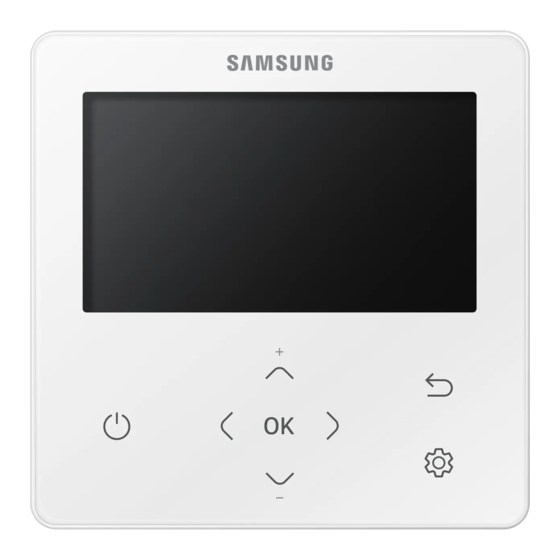
- Page 1 Air to Water Heat Pump User manual Wired remote controller MWR-WW10JN / Control Kit MIM-E03CN Thank you for purchasing this Samsung Product. Before operating this unit, please read this manual carefully and retain it for future reference.
-
Page 2: Table Of Contents
Contents Safety Information Safety Information Power Smart Features Remote Controller Operation Operating basic mode Domestic Hot Water (DHW) mode Power Smart Features Energy-Saving Operation Energy-Saving Operation Setting schedule Energy TDM (Time-Division Multi) Variables (TDM product Only) Setting Options Setting Options How to set the Options Current Time Setting (Example) Installation/Service mode... - Page 3 Business users should contact their supplier and check the terms and conditions of the purchase contract. This product and its electronic accessories should not be mixed with other commercial wastes for disposal. For information on Samsung’s environmental commitments and product-specific regulatory obligations, e.g. REACH, WEEE, Batteries, visit: www.samsung.com/uk/aboutsamsung/sustainability/environment/...
-
Page 4: Safety Information
Safety Information This content is intended to protect the user’s safety and prevent property damage. Please read it carefully for correct use of the product. WARNING Hazards or unsafe practices that may result in severe personal injury or death. CAUTION Hazards or unsafe practices that may result in minor personal injury or property damage. - Page 5 FOR OPERATION WARNING If the appliance generates a strange noise, a burning smell or smoke, unplug the product immediately and contact your nearest service centre. Failing to do so may result in electric shock or fire. To reinstall the product, please contact your nearest service centre. Failing to do so may result in problems with the product, water leakage, electric shock, or fire.
-
Page 6: Power Smart Features
Remote Controller Operation Operate the product by using the remote controller. Operating basic mode Press the button to enter the Setting screen from the Home screen with the Zone 1 or Zone 2 activated. On each screen, press the and then press the button to select any of Auto, Cool, and Heat modes. -
Page 7: Domestic Hot Water (Dhw) Mode
Domestic Hot Water (DHW) mode Press the button to enter the Setting screen from the Home screen with the DHW activated. On each screen, press the and then press the button to select and use any of Economic, Standard, Power, and Forced modes. - Page 8 Remote Controller Operation Adjusting desired temperature On each screen, press the button to adjust the temperature. NOTE You can adjust the desired temperature by 0.1, 0.5, 1 °C. (Default 0.5°C) Setting the set temperature On each screen, press the or button to select a desired menu and then press the the button.
-
Page 9: Power Smart Features
Power Smart Features There is a variety of useful functionality provided by the Samsung product. Operation status Use this to display the operation status: COMP operation, Back up heater, Booster heater, Solar, Back up boiler, Water pump, Water tank, Defrost operation, Freezing control, Water Tank Sterilization Operation, Indoor Thermostat Installation, Air to air operation, Solar PV, Smart grid, Eco Level, Demand Response. -
Page 10: Energy-Saving Operation
Energy-Saving Operation The product provides functions that allow you to reduce electricity consumption. Setting schedule Press the button, press the or , button to select Schedule, and then press the button. When you select Add a schedule, you can configure settings for Daily schedule, Weekly schedule, Yearly Schedule, and Holiday. -
Page 11: Energy
Energy Press the button, press the or , button to select Energy, and then press the button. You can see and set any of Energy Usage and Energy Setting. Classification Type Description Displays the Instantaneous Power, Weekly Energy Usage, Monthly Energy Usage, Yearly Energy Usage, Energy Usage over Last Year, and Operation Time in graph format. -
Page 12: Tdm (Time-Division Multi) Variables (Tdm Product Only)
Energy-Saving Operation TDM (Time-Division Multi) Variables (TDM product Only) Press the button, press the or , button to select Priority A2A, and then press the button. Setting FSV #5033 to '0' becomes 'Priority A2A', and setting to '1' becomes 'Priority DHW'. Under the installation of both A2A (Air-To-Air type air conditioner) and A2W (Air-To-Water type hydro unit) at the same time, our outdoor machine can supply its full capacity to the operating indoor machines (including A2A or A2W). -
Page 13: Setting Options
Setting Options How to set the Options 1 Press the button. 2 Press the button to select Option, and then press the button. 3 See the following pages to select the desired menu. Step 1 Step 2 Step 3 Step 4 Step 5 Description Default... - Page 14 Setting Options Step 1 Step 2 Step 3 Step 4 Step 5 Description Default ON/OFF Button Mute ON/OFF YYYY/MM/DD, Date Format DD/MM/YYYY, DD/MM/YYYY MM/DD/YYYY Date Year/Month/ 12/1 to 31 Current Time Time Format 12-Hour/24-hour 12-Hour Wired remote Hour/ Time 0 to 12/0 to PM 12 Hour 00 controller Minute/...
-
Page 15: Current Time Setting (Example)
Current Time Setting (Example) 1 Press the button. 2 Press the button to select Option, and then press the button. 3 Press the button to select User mode, and then press the button. 4 Press the button to select Wired remote controller, and then press the button. -
Page 16: Installation/Service Mode
Installation/Service mode Additional functions of the Wired Remote Controller 1 If you want to use the various additional functions for your Wired Remote Controller, press the buttons at the same time for more than 3 seconds. The password entry screen appears. 2 Enter the password, 0202, and then press the button. -
Page 17: Installation/Service Mode
Installation/Service mode NOTE Unavailable functions are marked inactive and they cannot be set. If communication initialization is needed after the setting, the system will reset automatically and communication will be initialized. Step 1 Step 2 Step 3 Description Default Service Call 16-digit phone number Number Service Timer... - Page 18 Installation/Service mode Step 1 Step 2 Step 3 Description Default Central : ON/OFF Normal Power : ON/OFF Mode : Heat/Cool/Auto DHW Power : ON/OFF Economic/Standard/ DHW Mode : Power/Forced Water Pump : ON/OFF Indoor Zone Indoor Zone BUH : ON/OFF Status Option Information...
- Page 19 Step 1 Step 2 Step 3 Description Default Micom Code : Micom code Program Version : Modified date Touch Code : Touch IC code Device Information Program Version : Modified date Graphic Image : Graphic image code Program Version : Modified date Erase All Service mode data...
- Page 20 Installation/Service mode Step 1 Step 2 Step 3 Description Default Water Inlet Temp.: Temperature Water Outlet Temp.: Temperature Backup Heater Temperature Outlet Temp.: Mixing Valve Temperature Outlet Temp.: Tank Temp.: Temperature Indoor Ambient Temperature Temp.: Self-Test Mode Indoor Ambient Temperature Display Temp.(Zone 2) : Water Outlet...
- Page 21 Step 1 Step 2 Step 3 Description Default Main address 00 to 4F Address RMC address 00 to FE Refer to the installation Product Option manual of the connected indoor unit. Indoor Unit Installation Option Option 1 Installation Option 2 MCU address 00 to 15 MCU Port...
- Page 22 Installation/Service mode NOTE Address is displayed in hexadecimal. Please refer to the following table. Hexadecimal Decimal Hexadecimal Decimal Hexadecimal Decimal Hexadecimal Decimal Hexadecimal Decimal English...
-
Page 23: How To Upload Or Download Field Settings (Example)
How to upload or download field settings (example) 1 Insert an SD card into the Sub PBA SD Card slot on the Hydro unit. 2 Select Field Setting Value in the Service mode. 3 Press the button to select FSV Upload/Download. NOTE Upload: Uploads the FSV data of the Hydro unit to the SD card. -
Page 24: Field Setting Mode
Field setting mode Air to Water Heat Pump: Only AE*** Model CAUTION Set the FSV value of the product other than the specified models by referring to the FSV label provided with the manual of the product, and then attach it on the control box's cover. The FSV values in the table are applied to the specified models. - Page 25 Remote Controller Setting Range: Code 10** Space Cooling With this default FSV settings, user can change the target water outlet temperature within the range Space Heating With this default FSV settings, user can change the target water outlet temperature within the range With this default FSV settings, user can change the target room temperature within the range of DHW Heating With this default FSV settings, user can change the target tank temperature within the range of...
- Page 26 Field setting mode Field Setting Value (FSV) 20** Code 20** : Water law design and external room thermostat Heating(2 WL’s for floor & FCU), Cooling(2 WL’s for floor & FCU), WL & Thermostat types The values in the following table are just examples for your understanding. MODEL CODE : MODEL CODE : Main Menu...
- Page 27 Water Law & Room Thermostat/ Wired remoted controller: Code 20** Heating WL Ts : Target Temp. at Floor/at FCU Cooling WL Ta : Ambient Temp. #2021/2031 #2022/2032 #2061/2071 #2062/2072 #2011 #2012 #2051 #2052 Water Law for Heating Outdoor air temperature range : Lower limit Upper limit With this default settings, the water outlet temperature by heating water law can be changed within Water out temperature range for floor/FCU applications respectively :...
- Page 28 Field setting mode External Room Thermostat (Field Option) To use wired remote controller for heating/cooling operation, both of the above settings should be set to 0 simultaneously. If not, thermostat controls system. #2092 2, #2092 3, Water pump Water pump Time Time Time...
- Page 29 Thermostat #2 which controls FCU has the priority for operation modes and the discharge water temperature. Samsung is not responsible for the accidents such as floor condensations which can occur by not connecting the valve to the zone #1 port of the Hydro Unit PBA.
- Page 30 Field setting mode Field Setting Value (FSV) 30** Code 30** : User’s options for Domestic Hot Water(DHW) tank heating The values in the following table are just examples for your understanding. MODEL CODE : MODEL CODE : AE200(260)RNW*** MIM-E03CN Function Main Menu &...
- Page 31 MODEL CODE : MODEL CODE : AE200(260)RNW*** MIM-E03CN Function Main Menu & Menu Code Code Setting Standard Setting Standard Item Step Unit Default Min. Max. Default Min. Max. Backup Heater 1step capacity Domestic Hot Water Addition Energy Backup Heater Tank Function metering 2step capacity...
- Page 32 Field setting mode [DHW Tank water temperature thermo on/off control] > T < T Tu : User set temp. HP MAX HP MAX T(C) T(C) T(C) : Temp. (Celsius) #3021 #3021 HP MAX HP MAX #3022 HP OFF #3023 HP OFF #3023 HP ON HP ON...
- Page 33 [Time variation control of Heat pump and booster heater of DHW] Heating request request #3025 Operation Booster Operation #3032 NOTE The FSV #4022 for booster heater priority should be set to “0 (both)” or “2” (booster) to use booster heater. If not(backup heater priority), the booster heater can be operated in case of no backup heater demand.
- Page 34 Field setting mode <Example of using BSH in hot water supply> (Thermo off / on operation temperature is used together) [Thermo on/off control of Heat pump and Booster Heater] #3033 BH OFF BH ON HP MAX #3022 HP OFF #3023 HP ON HP &...
- Page 35 NOTE Disinfection function is available only when a booster heater is connected. Check tank capacity, booster heater capacity, and booster heater for issues if disinfection operation does Forced DHW by User’s Input Forced mode can be activated by changing setting value from the setting (#3011, ”0” (No)). Forced mode shall be working depending on Timer setting (#3051, #3052).
- Page 36 Field setting mode Field Setting Value (FSV) 40** Code 40** : User’s options for heating devices including internal backup heater and external boiler The values in the following table are just examples for your understanding. MODEL CODE : MODEL CODE : AE200(260)RNW*** MIM-E03CN Function...
- Page 37 Additional heating option : 40** Heat Pump Variables for Space Heating FSV #4011 for DHW priority is set to “0(DHW)” (Default) as a default. Space heating gets a priority by setting FSV #4011 “1”, but this is only valid when the outdoor temperature is lower than the specified temperature defined by FSV #4012.
- Page 38 Field setting mode Mixing vavle Installation (Field Option) The FSV #4041 should be set to “1 or 2” to use mixing valve. ex) Heating <#4041=1> <#4041=2> FCU WL FCU WL #4042 Floor WL Floor temp FSV #4042 / #4043 is for adjusting temperature difference between Tw3 (Tw2) and Tw4. When using mixing valve, FSV #4046 should be matched with mixing valve running time charateristic.
- Page 39 Field Setting Value (FSV) 50** Code 50** : User’s options for extra functions The values in the following table are just examples for your understanding. MODEL CODE : MODEL CODE : Main AE200 (260)RNW*** MIM-E03CN Function Menu & Menu Code Setting Standard Setting Standard Code...
- Page 40 Field setting mode MODEL CODE : MODEL CODE : Main AE200 (260)RNW*** MIM-E03CN Function Menu & Menu Code Setting Standard Setting Standard Code Item Step Unit Default Min. Max. Default Min. Max. Application 0 (No) 0 (No) (Yes) (Yes) Setting Temp Shift Control Value (Cooling) Setting Temp Shift...
- Page 41 When applying to this logic, SAMSUNG controller come to get “Thermo off” condition for all operation. If not used for a long time, anti-freeze fluid shall be used for preventing damage to the unit in cold condition.
- Page 42 Field setting mode PV Control (Photovoltaics control) This is for energy saving by using the solar energy. same time.) Disable (Default) Activation NOTE Except for how water mode, This function is activated only for the outing mode. Hot water mode Thermo on operation regardless of outing mode: Setting temperature = Max temperature of hot water mode (FSV #1051) English...
- Page 43 Smart Grid Control NOTE MIM-E03CN(MONO Control Kit) model does not support this Smart grid function. Disable (Default) Activation Operation mode for Smart Grid Operation Mode Terminal 1 Terminal 2 Mode 1 Short Open Mode 2 Open Open Mode 3 Open Short Mode 4 Short...
-
Page 44: Dvm Hydro Unit: Only Am****Nbd*** Model
Field setting mode DVM Hydro unit: Only AM****NBD*** Model The values in the following table are just examples for your understanding. Code (Main Classification Function Detail Basic Min. Max. Step Unit + sub menu) Max. 1011 °C Temperature of general cooling leaving water Min. - Page 45 Code (Main Classification Function Detail Basic Min. Max. Step Unit + sub menu) Operation 3041 1 (Yes) 0 (No) Operation interval 3042 Fri (5) AllDay (7) Start time 3043 hour Disinfection Target temp. 3044 °C Holding time 3045 min. Max. operation time 3046 hour Solar heat panel H/P...
-
Page 46: Dvm Hydro Unit Ht: Only Am***Tnbf** Model
Field setting mode Code (Main Classification Function Detail Basic Min. Max. Step Unit + sub menu) A/7 (Ratio is determined based Ratio of hot water supply on the value of the Others 5061 compare to heating A)7 means Heating capacity=Hot water capacity NOTE The menu not supported by the product will not be displayed. - Page 47 Code (Main Classification Function Detail Basic Min. Max. Step Unit + sub menu) Auto heating of wired WL type 2041 1(WL1) remote controller Water Law Use of thermostat 0(No) Activating hot water DHW application 3011 0(No) 1(Yes) function Max. 3021 °C Stop 3022...
- Page 48 Field setting mode Code (Main Classification Function Detail Basic Min. Max. Step Unit + sub menu) Indoor heating 5014 °C temperature Temperature of auto 5017 °C heating WL1 water Outing mode Temperature of auto °C heating WL2 water Temperature of hot °C water Tank Temperature of hot...
- Page 49 Code: 20** #2021 or #2031 #2022 or #2032 #2011 #2012 Target water temperature Ambient (outdoor) temperatur 1) In case of outdoor temperature (Ta)°C < (Code #2011)°C Code #2041: 1 (Floor) Setting Ts = #2021 Code #2041: Setting 2 (Fan Coil Unit) Ts = #2031 Code #2041: Setting 1(Floor) Ts = #2021 + (#2022 - #2021) / (#2012 - #2011) * (Ta - #2011) Code #2041: Setting 2(Fan Coil Unit) Ts = #2031 + (#2032 - #2031)/(#2012 - #2011) * (Ta - #2011) Code #2041: Setting 1(Floor) Ts = #2022...
- Page 50 Field setting mode 3023: Offset temperature of DHW’s thermo on (Only Hydro Unit / Not Hydro Unit HT) 3024: When Heating and DHW mode is operating at the same time and heating mode is operating based on leaving water temperature with Thermo off, heating will operate for number of minutes stated in #3024 after every time maximum DHW operation time ends 3025: DHW operation time when heating and DHW mode is operating at the same time 3026: Heating operation time when heating and DHW mode is operating at the same time...
- Page 51 4012 : The temperature of forced heating priority (Refer to 4011) 4013 : If the ambient temperature > 4013, Heating Mode stops in auto mode. Code 50** User’s options for extra functions 501*: New target temperatures of each mode (Heating/Cooling/DHW) when “Outing” function is on 5011: Value of cooling leaving water temperature setting when “Outing”...
-
Page 52: Appendix
This maintenance should be carried out by SAMSUNG local technician. Besides keeping the remote controller clean by means of a soft damp cloth, no maintenance is required by the operator. - Page 53 <Emergency hot water supply_(when using FSV #3011, 3031)> Hot water is supplied only by the booster heater if the outdoor unit malfunctions. Enabling the function : Turn off the Control kit Dip S/W #2, and then turn the power off and on. Disabling the function : Turn on the Control kit Dip S/W #2, and then turn the power off and on.
-
Page 54: Troubleshooting Tips
Troubleshooting tips Troubleshooting tips It the unit has some problem to work properly, error codes will be displayed on the wired remote controller. The following table describes the explanation of the error codes. Display Explanation Short- or open-circuit error of the room temperature sensor of the Zone 2 indoor unit (detected only when the room thermostat is used) Short- or open-circuit error of the room temperature sensor of the Zone 1 indoor unit (detected only when the room thermostat is used) -
Page 55: Communication
Communication Display Explanation Communication error between remote controller and the Hydro unit Tracking error between remote controller and the Hydro unit Memory(EEPROM) Read/Write Error(Wired remote controller data error) E601, E604 E654 MEMORY(EEPROM) Read/Write Error (Wired controller data error) Micro SD Download connector card... -
Page 56: Water Pump & Flow Sensor
Troubleshooting tips Water pump & Flow Sensor Display Explanation Low flow rate error in case of low flow rate in 30 sec during water pump signals is ON(Starting) in case of low flow rate in 15 sec during water pump signals is ON(After starting) Normal flow rate error in case of normal flow rate in 10min during water pump signal is OFF E911... -
Page 57: Error Codes
Error codes Display Explanation Error Source Hydro Unit / Outdoor Unit communication connection error Hydro Unit Short- or open-circuit error of the room temperature sensor of the Zone 2 indoor unit (detected only when the room thermostat is Hydro Unit used) Short- or open-circuit error of the room temperature sensor of the Hydro Unit... - Page 58 Error codes Display Explanation Error Source [Inverter] IPM over current error Outdoor Unit Compressor overload error Outdoor Unit DC LINK over/low voltage error Outdoor Unit [Inverter] Compressor rotation error Outdoor Unit [Inverter] Current sensor error Outdoor Unit [Inverter] DC LINK voltage sensor error Outdoor Unit Outdoor unit EEPROM Read/Write Error Outdoor Unit...
- Page 59 Display Explanation Error Source Low flow rate error in case of low flow rate in 30 sec during water pump signals is Hydro Unit ON(Starting) in case of low flow rate in 15 sec during water pump signals is ON(After starting) Normal flow rate error Hydro Unit in case of normal flow rate in 10min during water pump signal...
- Page 60 COUNTRY CALL OR VISIT US ONLINE AT COUNTRY CALL OR VISIT US ONLINE AT www.samsung.com/ba/ www.samsung.com/uk/ BOSNIA 0333 000 0333 support support North www.samsung.com/mk/ IRELAND www.samsung.com/ie/ 023 207 777 Macedonia support (EIRE) support www.samsung.com/ MONTENEGRO www.samsung.com/de/ support GERMANY support www.samsung.com/si/ SLOVENIA www.samsung.com/fr/...