Samsung MWR-WE11N Installation Manual
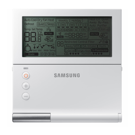
Wired remote controller, air conditioner
Hide thumbs
Also See for MWR-WE11N:
- Scheduling instructions (10 pages) ,
- User manual (32 pages) ,
- Installation manual (24 pages)

Related Manuals for Samsung MWR-WE11N


Summary of Contents for Samsung MWR-WE11N
-
Page 1: Installation Manual
Air Conditioner Installation manual Wired remote controller MWR-WE11N Thank you for purchasing this Samsung Product. Before operating this unit, please read this installation manual carefully and retain it for future refer- ence. DB68-06359A-02... -
Page 2: Safety Information
Safety Information This installation manual explains how to install a Wired Remote Controller connected to the indoor unit of your Trane system air conditioner. Please read this manual thoroughly before installing the product. (Please refer to appropriate installation for any optional product installation.) WARNING Hazards or unsafe practices that may result in severe personal injury or death. - Page 3 CAUTION Do not install the product where there’s combustible gas. Potential risk of fire and explosion. Ensure no water gets into the Wired Remote Controller. Potential risk of electric shock or fire. Install the air conditioner away from direct exposure to sunlight, in room temperature range of 0 °C(32 °F)~ 39 °C(102 °F).
-
Page 4: Wired Remote Controller Installation
Wired Remote Controller Installation Optional accessories Wired Remote Installation Cable Tie (2) Cable Clamp(3) M4X16 Screw (5) User Manual (1) U Terminal (6) Controller (1) Manual (1) through the inner area of the wall so that other people can’t reach it. External Dimensions [Unit : mm(inch)] 120.0(4.72) - Page 5 Wired Remote Controller Installation 1. Push the two hooks at the bottom of your Wired Remote Controller at the same time, and then pull up the front cover to separate it from the rear cover. Push the two hooks at the same time. hook to disassemble it easily.
- Page 6 Wired Remote Controller Installation Wired Remote Controller Installation 3. Using more than two screws, firmly affix the rear cover of the remote controller to the wall, and then connect the communication & power cable[(F3,F4) or (3, 4)], making sure these cables have reasonable length, to the terminal at the back of the cover.
- Page 7 Tracking Your Indoor Unit from the Wired Remote Controller Indicates tracking in progress Displays the total number of units searched 1. Tracking of your Wired Remote Controller will automatically start when you turn on the power after installation. 2. If you want to perform tracking again after installation, then press the Delete and ESC buttons at the same time for more than five seconds.
- Page 8 Wired Remote Controller Installation Individual Control with Your Wired Remote Controller When Connected to an Indoor Unit Only Outdoor Unit COM1(F1, F2) COM1(F1, F2) Indoor Unit Indoor Unit Indoor Unit COM2(F3, F4) COM2(F3, F4) COM2(F3, F4) Wired Remote Wired Remote Wired Remote Controller Controller...
- Page 9 Group Control with Your Wired Remote Controller Group control means that you are using one Wired Remote Controller to control two or more indoor units and When Connected to an Indoor Unit Only (1) Using One Wired Remote Controller to control three indoor Units Outdoor Unit COM1(F1, F2) COM1(F1, F2)
- Page 10 Wired Remote Controller Installation When Connected to an ventilator(ERV) Only COM1(F1, F2) COM1(F1, F2) COM1(F1, F2) Ventilator(ERV) Ventilator(ERV) Ventilator(ERV) COM2(F3, F4) COM2(F3, F4) Wired Remote Controller group address (RMC address), only the connected to COM2 controlled in group.
- Page 11 When Connected to an Indoor Unit and an ventilator(ERV) together Outdoor Unit COM1(F1, F2) COM1(F1, F2) COM1(F1, F2) Ventilator(ERV) Indoor Unit Indoor Unit Indoor Unit COM2(F3, F4) COM2(F3, F4) COM2(F3, F4) Wired Remote Controller Outdoor Unit COM1(F1, F2) Indoor Unit COM2(F3, F4) Outdoor Unit Wired Remote...
- Page 12 Wired Remote Controller Installation Controlling 2-Remote controller When Connected to an Indoor Unit Only Outdoor Unit COM1(F1, F2) Indoor Unit COM2(F3, F4) Wired Remote Wired Remote Controller (Master) When Connected to an ventilator(ERV) Only COM1(F1, F2) Ventilator(ERV) COM2(F3, F4) Wired Remote Controller Wired Remote Controller (Master) Wired Remote Controller.
- Page 13 When Connected to an Indoor Unit and an ventilator(ERV) Together Outdoor Unit COM1(F1, F2) Indoor Unit COM2(F3, F4) COM2(F3, F4) Ventilator(ERV) Wired Remote Wired Remote Controller (Master) controlled by 2-remote controller. Wired Remote Controller. (Refer to page19)
- Page 14 Wired Remote Controller Installation Initializing Your Wired Remote Controller Communication Wired remote controller must be initialized if installation status changes. 1. Press the Delete and ESC buttons at the same time for more than five seconds. connected to your Wired Remote Controller again.
- Page 15 Errors Displayed on Your Wired Remote Controller Error codes for the Wired Remote Controller and the product connected to your Wired Remote Controller will be displayed in the LCD display. LCD Display When an Error Occurs in Your Indoor/Outdoor Units (Product Group Display: A) The product address for the error will be displayed, followed by the error code.
-
Page 16: Wired Remote Controller Error Codes
Wired Remote Controller Installation Wired Remote Controller Error Codes Display Description communication. more than 3 minutes (Including communication error between indoor units and outdoor units) EEPROM error [Setting/Cancelling the Mode master indoor unit] mode). - Setting: Connect just 1 indoor unit and stop the operation. Then press and hold the Mode button for 5 seconds - Cancelling: Connect just 1 indoor unit and stop the operation. -
Page 17: Wired Remote Controller Installation/Service Mode
Wired Remote Controller Installation/Service Mode Additional Functions of Your Wired Remote Controller Data bit Main Menu Sub-menu 1 2 3... - Page 18 Wired Remote Controller Installation/Service Mode 1. If you want to use the various additional functions for your Wired Remote Controller, press the Delete and Set buttons at the same time for more than three seconds. You will enter the additional function settings, and the [main menu] will be displayed. 2.
- Page 19 Additional Functions of Your Wired Remote Controller In some cases, the setting may not possible or it may be not applied though it is set on the unit. communication will be initialized. Main Data Factory Function Description Unit menu menu setting 1 –...
- Page 20 Wired Remote Controller Installation/Service Mode Main Data Factory Function Description Unit menu menu setting Indoor unit room temperature 1,2,3 Room temperature °C 1,2,3 °C 1,2,3 °C Indoor unit EEV step 1,2,3 EEV step Use of central control 0 – No use, 1 - Use Use of drain pump 0 –...
- Page 21 Main Data Factory Function Description Unit menu menu setting 0 – OFF (Disabled or Cancelled) 1 – Completion 2 – 0 – Disable, 1 – Enable 1~3 steps (2 - Default) For the please refer to the installation manual of each product. Factory setting 0-No use, 1-Reset Power Master Reset 4)*...
- Page 22 Wired Remote Controller Installation/Service Mode The example of Wired Remote Controller option setting method 1. Press Delete and Set buttons at the same time for more than 3 seconds. (Main menu) will be displayed and then press the [∧]/[∨] button to select no.1. 2.
- Page 23 Memo...