Advertisement
Quick Links
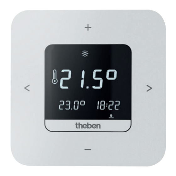
Digital clock thermostat
EN
RAMSES 811 top3
8119200
RAMSES 812 top3
8120200
RAMSES 812 top3 16A
8120210
RAMSES 813 top3 HF
8139200
1. General information
•
Digital clock thermostat for wall mounting or mounting
on flush-mounted box
•
The clock thermostat conforms with EN 60730-2-9 if
correctly installed
•
The RAMSES top3 series consists of 2 battery devices
(8119200, 8139200) and 2 power supply devices with
relay output of 10 A/16 A (8120200, 8120210)
•
External input to connect an external temperature
sensor, floor sensor etc.
•
Radio-controlled system RAMSES 813 top3 HF Set 1 and
Set A consisting of RAMSES 813 top3 HF and receiver
•
The RAMSES top3 app (for Android, iOS) allows settings
via mobile devices
•
Direct Bluetooth Low Energy (BLE) connection between
app and RAMSES top3 devices
•
Optional accessories: Floor sensor (9070321),
Temperature sensor RAMSES (9070459)
2. Safety
Assembly and installation should only be carried
out by a qualified electrician, somebody who has
completed appropriate professional training and
has the knowledge and experience necessary to be
able to recognise and avoid the potential dangers
posed by electricity.
Before installation/disassembly, disconnect the
supply voltage and ensure that the parts are no
longer live.
Prior to commissioning and using the product, read
and observe all the operating instructions.
3. Proper Use
•
Digital clock thermostat for time-dependent monitoring
and control of the room temperature in single-family
houses, offices, etc.
•
Only operate the devices in dry indoor rooms (no bath-
rooms, etc.)
4. Installation
309952 00
28 February 2023
You can mount the clock thermostat either on the wall (not
8120210) or on a flush-mounted box.
Batteries
The devices RAMSES 811 top3 and RAMSES 813 top3 HF are
battery devices.
Only use AA batteries LR6, 2 x 1.5 V.
†
Ensure correct polarity.
†
Mount the clock thermostat
L For wall mounting. With RAMSES 813 top3 HF, a stand is
also included in the set.
!
Protect the clock thermostat from moisture, dust, direct
sunlight, thermal radiation and draughts.
!
On the battery devices (8119200 + 8139200), the termi-
nal box cover plate must be fixed with the screws.
Position the clock thermostat on an interior wall, at about
†
eye level (approx. 1.50-1.60 m).
Fix the mounting plate directly to the wall or to a flush-
†
mounted box using the holes .
Assign and wire the conductors.
†
Insert the terminal box cover plate (top must point
†
upwards).
If necessary, tighten the screws and insert the batteries
†
correctly (only with 8119200 + 8139200) .
Put on the clock thermostat .
†
Dismount the clock thermostat
!
For battery change, open the device according to the
illustration, as it could be destroyed if not done so.
Insert the screwdriver into the opening and push up slightly
†
to open the device.
1
Advertisement

Related Manuals for Theben RAMSES 811 top3


Summary of Contents for Theben RAMSES 811 top3
- Page 1 8120210) or on a flush-mounted box. RAMSES 811 top3 Batteries 8119200 RAMSES 812 top3 The devices RAMSES 811 top3 and RAMSES 813 top3 HF are 8120200 battery devices. RAMSES 812 top3 16A 8120210 Only use AA batteries LR6, 2 x 1.5 V.
- Page 2 (if one is being used). Faulty connections will damage the device. RAMSES 811 top3 The following sets are available: 1. RAMSES 813 top3 HF Set 1 L External sensors such as a floor sensor (9070321) or a temperature sensor (9070459) can be connected to the external input (ext.
- Page 3 7. Menu 2. RAMSES 813 top3 HF Set A Operating modes main menu Weekly programs P1–P3 1 2 3 Comfort temperature Setbacktemperature (Eco) Frost protection temperature Set date and time Service/Settings Receiver REC 11 Button channel 5 4 3 2 1 Settings submenu ...
-
Page 4: Initial Operation
8. Initial operation Programs P1 – P3 There are 3 preset weekly programs available: L The summer/winter time rule for Central Europe is preset. Mon Tue Wed Thu Fri Sat Sun After the RAMSES top3 devices have been mounted and connected and the batteries have been inserted in 8119200, 8139200, the date/time and –... - Page 5 3. Set wall compensation L If the Bluetooth symbol appears permanently in the dis- play, the device is connected to the app. If the installation location is unfavourable, this may lead to variations in temperature between the detected and actual L If the button –...
- Page 6 Examples for settings With a set optimisation of 5 min/K, the thermostat sends the heating request earlier, as follows: Amplitude Period Heating Room properties duration Set temperature at 06.00 a.m. 23 °C 0.2 K 5 minutes ∙ Fan heater ∙...
- Page 7 8. PIN Fault This function can be used to assign a new PIN. In the event of a fault or error, the error code flashes on the display. The warning triangle also flashes. All other display L The factory setting for the PIN is 0000. symbols are cleared.
- Page 8 RAMSES top3 app Settings, device management App info, operating instructions Quick selection Device list Set temperature, adjustable in increments of 0.2 °C (2 °C – 30 °C) Info: device type, external input, serial number, etc. L A maximum of 24 switching times can be set per program, a total of 42.
- Page 9 3. External input The external input can be configured for various external sen- sors, see Page 6. L The functions in this submenu have to be set by the quali- fied electrician. In the settings, language, temperature (comfort, eco (setback), Error indicator on RAMSES top3 frost protection), wall compensation, optimisation, etc.
- Page 10 9. Factory settings 6. Set window detection Here you can reset all functions to the factory settings. Here you can choose between On and Off, for more informa- tion see Page 5. 10. Set display 7. Set pump protection You can adjust the appearance of your display, see also Page 5.
- Page 11 Device management Connect the clock thermostat to the receiver Press > 2 x and go to Settings using >. The symbol † flashes. Confirm with +. † Use + or – to select wireless → † Confirm with >. † The wireless symbol flashes and the channel is connected to the receiver.
-
Page 12: Troubleshooting
12. Technical data L The channels on the receiver must be off, i.e. the corre- sponding LED must be off. Battery devices (8119200, 8139200) Press button C1 at the receiver for 5–8 s. † Operating voltage Batteries: 2 x 1.5 V LR6 AA ▻... -
Page 13: Dimensions Diagrams
Rated impulse voltage 4 kV Pollution degree Software class Theben AG herewith declares that this type of radio installation com- plies with Directive 2014/53/EU. The complete text of the EU Decla- ration of Conformity is available at the following Internet address: www.theben.de/red-konformitaet Cleaning and service Only use a dry, soft cloth to clean the device surface.