Table of Contents
Advertisement
Quick Links
Operating instructions for RAMSES 813 top2 HF and
RAMSES 833 top2 HF
Dear client,
if you have the newer device, please use page 1 to 38
RAMSES
RAMSES 813 top2 HF
8139500
RAMSES 833 top2 HF
8339500
Montage- und
Bedienungsanleitung
Raumthermostat
D GB
F
E
I
NL
and if you have the older one, please use page 39 to 75 of this pdf.
RAMSES
RAMSES 813 top2 HF
813 9 500
RAMSES 833 top2 HF
833 9 500
Montage- und
Bedienungsanleitung
Raumthermostat
D GB
F
E
I
NL
RAMSES 833 top2 HF
RAMSES 833 top2 HF
309373 05
D
309373 04
D
Advertisement
Chapters
Table of Contents

Related Manuals for Theben RAMSES 813 top2 HF


Summary of Contents for Theben RAMSES 813 top2 HF
- Page 1 Operating instructions for RAMSES 813 top2 HF and RAMSES 833 top2 HF Dear client, if you have the newer device, please use page 1 to 38 309373 05 RAMSES RAMSES 813 top2 HF 8139500 RAMSES 833 top2 HF 8339500 Montage- und...
- Page 2 309373 05 RAMSES RAMSES 813 top2 HF 8139500 RAMSES 833 top2 HF 8339500 Installation and operating instructions Room thermostat D GB RAMSES 833 top2 HF...
-
Page 3: Table Of Contents
Contents TIME/DATE Set date, time and summer/winter time 23 Basic safety instructions HOLIDAY Screen and keys Set holiday program etc. Operating instructions Connection/installation/uninstallation USER SETTINGS Fit/change batteries/Reset Set language Receivers/HF Test/Coding Set display Initial start-up Set LCD backlight Set contrast User operating level Set keypad lock INFO key... -
Page 4: Basic Safety Instructions
Basic safety instructions WARNING Danger of death through electric shock or fire! Installation should only be carried out by a qualified electrician! • The devices are designed for different types of installation as described below Designated use • The room thermostat regulates the room temperature in houses, offices etc. via radio control •... -
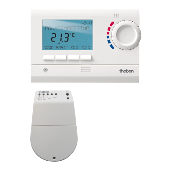
Page 5: Screen And Keys
Screen and keys Operating instructions Display programmed Time display 1. Read text line switching times Flashing text/symbol Temperature display represents query Text line Days of the week from 1–7 2. Make a decision Function keys: – INFO – MENU – T°/H –... -
Page 6: Connection/Installation/Uninstallation
Connection/installation WARNING Warning, danger of death through electric shock! Must be installed by qualified electrician! Disconnect power source. Cover or shield any adjacent live components. Ensure device cannot be switched on! Check power supply is disconnected. ... - Page 7 Wall installation Attach device to wall using the optionally available back wall set (907 0 605). This enables the use of the external input with the RAMSES 833 top 2 sets (see pages 33 ff.). Ensure installation height of approx. 1.5 m and check reception quality. Free-standing installation ...
- Page 8 Insert batteries Replace batteries Only be carried out by a qualified 1. B attery symbol flashes on display, control- electrician. ler remains active. The batteries should be Only use alkaline 1.5 V AA replaced. 2. T he display flashes, the controller cannot be batteries.
- Page 9 REC 1/REC 2/REC 11/REC 21 receivers REC 11/REC 21 for mains operation REC 1/REC 2 for wall installation 5 4 3 2 1 5 4 3 2 1 A Switching pre-selection channel 1 E Signal strength display B Switching status display channel 1 Range approx.
- Page 10 Installation and connection of receivers REC 1 (1 channel) REC 11 Connect device to terminals 1, 2, 3. Connect device to terminals. REC 2 (2 channels) Connection 1: REC 21 Connect device to terminals 1, 2, 3. Plug device into socket.
- Page 11 REC 1/REC 2/REC 11/REC 21 receivers Align antenna At least one green LED must light up for opti- Connect REC 1/REC 2 mum reception. to operating voltage. Align antenna vertically. Switching pre-selection of REC 1/REC 2/ In the event of errors (several LEDs light up), REC 11/REC 21 align antenna so that as few LEDs as pos- sible light up.
- Page 12 Coding Coding channel C2 (e. g. room 2) Transmitters and receivers are pre-configured with each other ex works. P ress key C2 on REC 2 (e.g. room 2) for Delete old coding before entering new one. approx. 5 seconds. Test of channel 1/channel 2 (e.g.
- Page 13 General information on radio transmission Transmission Since radio signals are electromagnetic waves, Please note: Moisture in the material hinders the signal from the sender to the receiver is transmission! dampened (referred to as transmission range limitation). There are also further interference Dry material Material Transmission...
-
Page 14: Initial Start-Up
Initial start-up After inserting batteries, press the right key The RAMSES 813 top2 HF devices are basic for more than 3 seconds and follow on- devices and the RAMSES 833 top2 HF devic- screen display (see fig.). es are comfort devices. -
Page 15: Info Key
& User information Note: The whole screen, except for temperature and time, is faded out after 5 seconds. Press the INFO key to restore screen. This setting can be changed under USER SETTINGS/DISPLAY. INFO key – View settings The INFO key allows you to access current ROOM TEM 21.6 °C... -
Page 16: T°/H Key - Setting The Timer Function
T°/H key – Setting the timer 6°C key – Set fixed function temperature Press T°/H key. REQUIRED TEMPERATURE Press 6°C key. REQUIRED TEMPERATURE (6 °C–30 °C) appears. (6 °C–30 °C) appears. Use the + or – keys on the rotary control Use the + or –... -
Page 17: Change Target Temperature
Change target temperature Use rotary control to make changes The following applies to all programs: In standard operation mode, you can temporar- The broken bar in the top left of the display ily change current target temperature via the shows the number of menu points in the rotary control. -
Page 18: Temperature Programs
Temperature programs RAMSES top2 devices have several Mo Tu We Thu Fr Sa Su preset programs. – P1 – P2 – P3 Use the MENU/PROGRAMMING key to access selection of active temperature program. Change temperature programs (P1, P2, P3) The programs are adjusted using the MENU, key in the PROGRAMMING menu (see page 20ff.) 12:00... -
Page 19: Menu - Overview
MENU – Overview MENU +/– +/– +/– +/– +/– TIME/ HOLIDAY USER SETTINGS PROGRAMM PROFESSIONAL DATE SETTINGS LANGUAGE PROG P1 YEAR START WALL COMP HOLIDAY PROG P2 YEAR OPTIMISE MONTH DISPLAY MONTH PUMP PROG P3 BACKLIGHT PROTECTION CONTRAST CLEAR PROG HOUR INPUT HOUR... -
Page 20: Programming
PROGRAMMING Programs P1–P3 are preset but they can be Program P1 (preset) amended or deleted. Mon–Fri 21 °C 6.00–22.00 A maximum of 24 switching times can be set otherwise 17 °C per program, up to a total of 42. Sat–Sun 21 °C 7.00–23.00 MENU... -
Page 21: Reset Switching Time
Reset switching time MENU PRO- GRAMMING PROG P1 PROG P2 Press MENU key. The display shows PROGRAMMING. Confirm by pressing OK. P1 NEW The display shows, for example, PROG P1. Confirm by pressing OK. ... -
Page 22: Change Or Clear Switching Time
Change or clear switching time MENU PRO- GRAMMING PROG P1 PROG P2 Press MENU key. The display shows PROGRAMMING. Confirm by pressing OK. P1 CHANGE P1 CLEAR The display shows, for example, PROG P1. Confirm by pressing OK. ... -
Page 23: Delete Program
Check switching time Delete program Press MENU key. The display shows Confirm PROGRAMMING by pressing OK. PROGRAMMING. Select CLEAR PROG using the + or – keys. Confirm by pressing OK. Confirm by pressing OK. The display shows The display shows, for example, PROG P1. -
Page 24: Time/Date
TIME/DATE MENU Set date, time and summer/winter TIME/DATE rule YEAR Press MENU key. The display shows MONTH PROGRAMMING. Selected TIME/DATE using the + or – keys or the rotary control. HOUR Confirm by pressing OK. The display shows YEAR. MINUTE Change hours, minutes etc. -
Page 25: Holiday
HOLIDAY MENU HOLIDAY Set Holiday program START HOLIDAY YEAR Press MENU key. The display shows MONAT PROGRAMMING. Selected TIME/DATE using the + or – keys or MONTH the rotary control. HOUR Confirm by pressing OK. The display shows START HOLIDAY. - Page 26 Check/clear holiday program Switch off holiday program (only possible with a programmed holiday HOLIDAY is displayed on screen during the period) programmed holiday period. The controller can HOLIDAY only be operated once the holiday mode has been switched off. CLEAR CHECK Confirm HOLIDAY on display with YEAR...
-
Page 27: User Settings
Briefly interrupt holiday program USER SETTINGS and restart Set language The program can be interrupted during the holiday period and restarted with the Press MENU key. The display shows available data. PROGRAMMING. MENU Selected USER SETTINGS using USER SETTINGS Confirm HOLIDAY on screen the + or –... -
Page 28: Set Display
Set display Confirm DISPLAY 12:00 1 = Standard display: after 5 21.3 °C by pressing OK. seconds all display content Use + or – keys or except for temperature and rotary control time are faded out (factory MENU to select values 1–4. -
Page 29: Set Lcd Backlight
Set LCD backlight Set contrast (only with RAMSES 833 top2 HF) The brightness of the backlighting can be set Screen contrast can be set at different levels. at different levels. Confirm LCD BACKLIGHT by pressing OK. Confirm CONTRAST by pressing OK. The display shows, for example, 3. -
Page 30: Set Keypad Lock
Keypad lock Briefly interrupt keypad lock The keypad lock can be interrupted to allow The device is fitted with a keypad lock that programming etc. The keypad lock is reacti- is switched on or off via software program. vated once changes are completed and the When the keypad lock is switched on, a key symbol appears on the display and pressing a standard operating mode is returned to. -
Page 31: Operating Level For Specialist Personnel
Operating level for specialist personnel PROFESSIONAL SETTINGS – Set wall compensation If the installation site is not in a good place, this may lead to a variation MENU in temperature between the detected and actual room temperature. PROFESSIONAL This can be corrected by using wall compensation. SETTINGS WALL COMP Press MENU key. -
Page 32: Set Optimisation
Set optimisation thermostat requests the heating requirement earlier as follows: The optimisation function allows you to achieve a certain room temperature at a • Setpoint temperature at 06.00 --> 23 °C desired switching point The display shows how • Actual temperature --> 17 °C many minutes earlier the heating has to be •... -
Page 33: Set Pump Protection
Set external input Set pump protection The external input on the RAMSES 833 top2 HF Pump protection is not activated in the fac- can be configured for various external sensors. tory. But it can be set in the PROFESSIONAL SETTINGS menu. CAUTION! Input is active, therefore do not use external voltage. - Page 34 The following options are available with the individual sensors/contacts Floor sensor: Mode 1 no options, floor temperature control, floor temperature is shown on screen Mode 2 Floor temperature control, floor temperature level can be set between 20 °C and 30 °C, room temperature is shown on display;...
- Page 35 Phone switch: Temperature selection Select temperature level for controller when the phone switch is switched on. Time selection Select time until phone switch turns off automatically. PHONE SWITCH is shown on screen if the phone switch is switched on. The switched contact must be switched off manually to allow the control to be used again.
-
Page 36: Set Controller
Set controller Use + or – keys or rotary control to implement settings and Controller characteristics of pulse confirm by pressing OK. CONTROL duration controller With adapted heating systems, a PD controller is noted for its short transient time, minimal PD CONTROL HYST overshoot and therefore high control, accuracy. -
Page 37: Hf Setting
HF setting Set maintenance period With maintenance, it is a question of a SETTINGS "reminder function". RF TEST CODING C onfirm SERVICE by pressing OK. The dis- play shows MONTHS BEFORE NEXT SERVICE. RF TEST SEND CODE U se the + or – keys or the rotary control to ACTIVE enter the value and confirm by pressing OK. -
Page 38: Technical Data
Technical data RAMSES 813 top2 HF / RAMSES 833 top2 HF Batteries: 2 x alkaline batteries 1.5 V, REC 1 + REC 2 (868 MHz) AA type Nominal voltage: 230 V~ +/–10 % 50 Hz Power reserve during Contact: Changeover switch, floating... - Page 39 309 373 03 RAMSES RAMSES 813 top2 HF 813 9 500 RAMSES 833 top2 HF 833 9 500 Installation and operating instructions Room thermostat RAMSES 833 top2 HF...
- Page 40 Contents Programming Reset switching time Basic safety instructions Change or delete switching time Screen and keys View switching time Operating instructions Delete program Connection/installation/dismantling Set language Fit batteries/Reset Set display Receivers/HF test/Coding Set LCD light Initial start-up Set contrast Keypad lock User operating level Factory setting INFO key...
-
Page 41: Basic Safety Instructions
Basic safety instructions WARNING Danger of death through electric shock or fire! Installation should only be carried out by a qualified electrician! • The devices are designed for different types of installation as described below Designated use • The room thermostat regulates the room temperature in houses, offices etc. via radio control •... -
Page 42: Screen And Keys
Screen and keys Operating instructions Display programmed Time display 1. Read text line switching times Flashing text/symbol Temperature display represents query Text line Days of the week from 1–7 2. Make a decision Function keys: – MODE – ECO – PARTY –... -
Page 43: Connection/Installation/Dismantling
Connection/installation WARNING Warning, danger of death through electric shock! Must be installed by qualified electrician! Disconnect power source. Cover or shield any adjacent live components. Ensure device cannot be switched on! Check power supply is disconnected. ... - Page 44 Wall installation Attach device to wall using the optionally available back wall set (907 0 605). This enables the use of the external input with the RAMSES 833 top 2 sets (see pages 33 ff.). Ensure installation height of approx. 1.5 m and check reception quality. Free-standing installation ...
- Page 45 Insert batteries Replace batteries 1. B attery symbol flashes on display, control- Only be carried out by a qualified electrician. ler remains active. The batteries should be Only use alkaline 1.5 V AA replaced. 2. T he display flashes, the controller cannot be batteries.
- Page 46 REC 1/REC 2/REC 11/REC 21 receivers REC 11/REC 21 for mains operation REC 1/REC 2 for wall installation 5 4 3 2 1 5 4 3 2 1 E Signal strength display A Switching pre-selection channel 1 B Switching status display channel 1 C Level display for reception strength Range approx.
- Page 47 Installation and connection of receivers REC 1 (1 channel) REC 11 Connect device to terminals 1, 2, 3. Connect device to terminals. REC 2 (2 channels) REC 21 Connection 1: Connect device to terminals 1, 2, 3. Plug device into socket.
- Page 48 REC 1/REC 2/REC 11/REC 21 receivers Align antenna At least one green LED must light up for opti- Connect REC 1/REC 2 mum reception. to operating voltage. Align antenna vertically. Switching pre-selection of REC 1/REC 2/ In the event of errors (several LEDs light up), REC 11/REC 21 align antenna so that as few LEDs as pos- sible light up.
- Page 49 Coding Transmitters and receivers are pre-configured Coding channel C2 (e. g. room 2) with each other ex works. P ress key C2 on REC 2 (e.g. room 2) for Delete old coding before entering new one. approx. 5 seconds. Test of channel 1/channel 2 (e.g.
- Page 50 General information on radio transmission Transmission Since radio signals are electromagnetic waves, Please note: Moisture in the material hinders the signal from the sender to the receiver is transmission! dampened (referred to as transmission range limitation). There are also further interference Dry material Material Transmission...
-
Page 51: Initial Start-Up
Initial start-up After inserting batteries, press the right key The RAMSES 813 top2 HF devices are basic for more than 3 seconds and follow on- devices and the RAMSES 833 top2 HF devic- screen display (see fig.). es are comfort devices. -
Page 52: Info Key
& User information Note: The whole screen, except for temperature and time, is faded out after 5 seconds. Press the INFO key to restore screen. This setting can be changed under OPTIONS/DISPLAY. INFO key – View settings The INFO key allows you to access current ROOM TEMP 21.6 °C... -
Page 53: Party Key
PARTY key – Set PARTY function ECO key – Set ECO function Press PARTY key. Press ECO key. The display shows PARTY TARGET TEMP The display shows ECO TARGET TEMP 23,0 °C. 17,0 °C. Provided the whole screen is shown, the Provided the whole screen is shown, the ECO PARTY key flashes to display the set party key flashes to display the set party mode. -
Page 54: Temperature Programs
Temperature programs Use rotary control to make changes RAMSES top2 devices have several preset programs. In standard operation mode, you can temporar- – P1 ily change current setpoint temperature via the – P2 rotary control. It is not stored in the program –... - Page 55 The following applies to all programs: The broken bar in the top left of the display shows the number of menu points in the re- levant menu. The flashing cursor indicates the point in the menu that you are currently in. .
-
Page 56: Mode Key - Change/Program Settings
MODE key – Change/program settings Using the MODE key and selecting the SETTINGS menu point brings up the programming and setting mode. Select preset program Press MODE key. MODE P1 ACTIVE ACTIVATE P2 ACTIVATE P3 PERM PERM... -
Page 57: Mode - Settings- Overview
YEAR DISPLAY COMFORT 1 MONTH YEAR PROG P3 PUMP BACKLIGHT PROTECTION CONTRAST MONTH CLEAR EXT. TEMP REDUCED PROG INPUT FROST HOUR CONTROLLER LOCK PROTECTION FACTORY SU/WI RULE HOLIDAY END RF SETTINGS MAINTENANCE INFO FROST PROTECTION only RAMSES 813 top2 HF... -
Page 58: Set Date, Time And Summer/Winter Time
Change target temperature Set date, time and summer/ winter time Confirm TARGET TEMP by pressing OK. Confirm TIME/DATE by pressing OK. The display shows COMFORT 3. The display shows HOUR. SETTINGS Use + or – keys or Change hours, minutes rotary control to change value. -
Page 59: Set Holiday Program Etc
Set Holiday program Confirm HOLIDAY by pressing OK. SETTINGS The display shows HOLIDAY START. HOLIDAY Select year, month, day etc. in succession. START HOLIDAY Use + or – keys or YEAR rotary control to change value. Confirm each setting by pressing OK. MONTH Finally, enter END HOLIDAY in same way as START HOLIDAY entry. - Page 60 Set temperature preselection Switch off holiday program HOLIDAY is displayed on screen during the programmed holiday period. The controller can only be operated once the holiday mode has FROST REDUCED COMFORT 1 COMFORT 2 ... been switched off. PROTECTION TEMP.
- Page 61 Programming Briefly interrupt holiday program and restart Programs P1–P3 are preset The program can be interrupted during the but they can be amended or deleted. holiday period and restarted with the available A maximum of 24 switching times can be set per data.
-
Page 62: Reset Switching Time
Reset switching time Confirm by pressing OK. MODE – SETTINGS– PROGRAMMING PROG P1 Confirm PROGRAMMING by pressing OK. The display shows, for example, PROG P1. Confirm PROG P1 by pressing OK. Press NEW key. P1 Mon - Fri P1 Sat-Sun DAILY P1 MONDAY... -
Page 63: Change Or Delete Switching Time
Change or delete switching time PROG P1 Confirm PROGRAMMING by pressing OK. EDIT The display shows, for example, PROG P1. Confirm PROG P1 by pressing OK. CHANGE CLEAR Press EDIT key. The display shows CHANGE or CLEAR. 6:00 6:00 Confirm CHANGE by pressing OK. -
Page 64: View Switching Time
View switching time Delete program Confirm PROGRAMMING by pressing OK. Confirm PROGRAMMING The display shows, for example, PROG P1. by pressing OK. Confirm PROG P1 by pressing OK. Select CLEAR PROG using the + or – keys. Press NEXT key Confirm by pressing OK. -
Page 65: Set Language
Set language Confirm LANGUAGE by pressing OK. 12:00 1 = Standard display: after 5 21.3 °C The display shows, for example, GERMAN. seconds all display content Use + or – keys or except for temperature and rotary control to SETTINGS time are faded out. -
Page 66: Set Contrast
Set LCD backlight Set contrast (only with RAMSES 833 top2) The brightness of the backlighting can be set Screen contrast can be set at different levels. at different levels. Confirm CONTRAST by pressing OK. Confirm LCD BACKLIGHT by pressing OK. The display shows, for example, 8. -
Page 67: Keypad Lock
Keypad lock Briefly interrupt keypad lock The keypad lock can be interrupted to allow The device is fitted with a keypad lock that programming etc. The keypad lock is reacti- is switched on or off via software program. vated once changes are completed and the When the keypad lock is switched on, a key symbol appears on the display and pressing a standard operating mode is returned to. -
Page 68: Operating Level For Specialist Personnel
Operating level for specialist personnel Set wall compensation SETTINGS SERVICE If the installation site is not in a good place, this may lead to a variation in temperature between the detect- WALL COMP ed and actual room temperature. This can be corrected OPTIMISE by using wall compensation. -
Page 69: Set Optimisation
Set optimisation thermostat requests the heating requirement earlier as follows: The optimisation function allows you to • Setpoint temperature at 06.00 --> 23 °C achieve a certain room temperature at a • Actual temperature --> 17 °C desired switching point The display shows how •... -
Page 70: Set Pump Protection
Set pump protection Set external input Pump protection is not activated in the factory. The external input on the RAMSES 833 top2 But it can be set in the SERVICE menu. can be configured for various external sensors. CAUTION! Input is active, therefore Confirm PUMP PROTECTION do not use external voltage. - Page 71 The following options are available with the individual sensors/contacts Floor sensor: Mode 1 no options, floor temperature control, floor temperature is shown on screen Mode 2 Floor temperature control, floor temperature level can be set between 20 °C and 30 °C, room temperature is shown on display;...
- Page 72 Telephone switch: Temperature selection Select temperature level for controller when the telephone contact is switched on. Time selection Select time until telephone contact turns off automatically. TELEPHONE SWITCH is shown on screen if the telephone contact is switched on. The switched contact must be switched off manually to allow the control to be used again.
-
Page 73: Set Controller
Set controller Use + or – keys or rotary control to implement settings and confirm Controller characteristics of pulse by pressing OK. CONTROL duration controller With adapted heating systems, a PD controller is noted for its short transient time, minimal PD CONTROL HYST CONTROL... -
Page 74: Hf Setting
HF setting Set maintenance period With maintenance, it is a question of a SETTINGS "reminder function". RF TEST CODING C onfirm SERVICE by pressing OK. The dis- play shows MONTHS BEFORE NEXT SERVICE. RF TEST SEND CODE U se the + or – keys or the rotary control to ACTIVE enter the value and confirm by pressing OK. -
Page 75: Technical Data
Technical data RAMSES 813 top2 HF / RAMSES 833 top2 HF Batteries: 2 x alkaline batteries 1.5 V, REC 1 + REC 2 (868 MHz) AA type Nominal voltage: 230 V~ +/–10 % 50 Hz Power reserve during Contact: Changeover switch, floating...