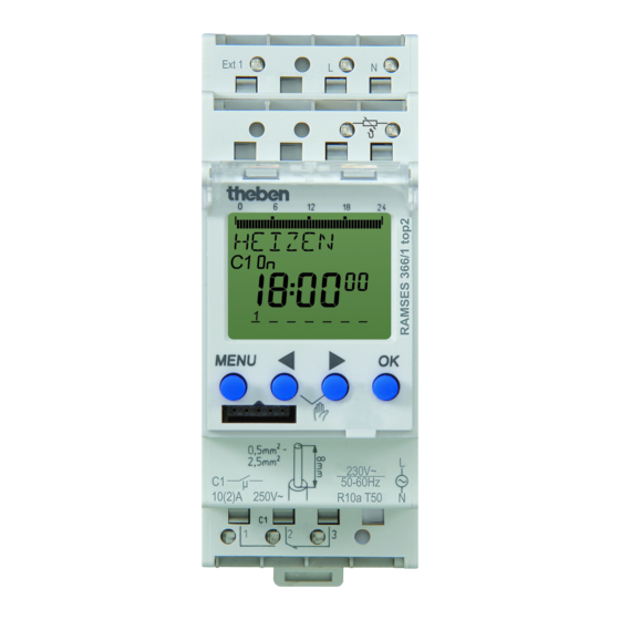
Theben RAMSES 366/1 top2 Operating Instructions Manual
Digital clock thermostat
Hide thumbs
Also See for RAMSES 366/1 top2:
- Operating instructions manual (27 pages) ,
- Installation and operating instructions manual (24 pages)
Advertisement
Quick Links
Digital clock thermostat
EN
RAMSES 366/1 top2
3660100
1. Basic safety information
WARNING
Danger of death through electric shock or fire!
Installation should only be carried out by a
¾
¾
professional electrician!
•
The device is designed for installation on DIN top hat
rails (in accordance with EN 60715)
•
Equivalent to Type 1 B
•
Power reserve (10 years) is reduced if memory card is
inserted (using battery power)
!
OBELISK top2 memory card: Avoid mechanical overload
and contamination during storage/transportation
2. Proper use
•
The digital clock thermostat is intended for time-depen-
dent monitoring and control of the the room temperature
•
Use only in closed and dry rooms of halls, industrial
buildings
•
2 different temperature sensors can be used: a non-
adjustable sensor (9070191) and an adjustable sensor
(9070192), which can be used for temporarily and adjus-
ting the set temperature, if required
Disposal
Dispose of device in environmentally sound manner
†
¾
3. Installation and connection
Mounting the Digital clock thermostat
WARNING
Danger of death through electric shock or fire!
Installation should only be carried out by a
¾
¾
professional electrician!
307185
click
Federsteckklemme
Federsteck-
klemmen-
öffner
Prüfabgriff
Speicherkarte
OBELISK top2
(9070404)
Mount on DIN top hat rails (as defined in EN 60715)
†
¾
Switched voltage-free
†
¾
Ensure device cannot be switched on
†
¾
Check absence of voltage
†
¾
Earth and bypass
†
¾
Cover or shield any adjacent live components
†
¾
Connecting the cable
Wiring diagram
L N
Ext1
C1
1 2 3
Strip cable to 8 mm (max. 9)
†
¾
Insert cable in the open DuoFix® plug-in terminal at 45°
†
¾
L 2 cables per terminal position possible
To open the DuoFix® plug-in terminal, press screwdriver
†
¾
downwards
Disconnecting the cable
Use the screwdriver to push the load line connection
†
¾
opener downwards
Leitung 45°
max. 50 m
N
L
L
L
1
Advertisement

Related Manuals for Theben RAMSES 366/1 top2


Summary of Contents for Theben RAMSES 366/1 top2
- Page 1 307185 Digital clock thermostat RAMSES 366/1 top2 3660100 click Leitung 45° 1. Basic safety information Federsteckklemme WARNING Danger of death through electric shock or fire! Installation should only be carried out by a ¾ ¾ Federsteck- professional electrician! klemmen- öffner •...
-
Page 2: Device Description
4. Device description Overview of navigation menu MENU Display & buttons TEMPERATURE PROGRAM TIME/DATE CHECK TIME Programmed MODIFY CHECK SET DATE Operating ON times mode: Frost MODIFY SU--WI Date display Channel status ON = On DELETE FORM DATE Time display OFF = Off FORM TIME Days of the... -
Page 3: Settings And Functions
5. Settings and functions Request temperature program For comfort, decrease and frost temperature Set switching time MENU TEMPERATURE L Without programmed switching times, the clock thermos- CHECK ACTUAL TEMP 20.0 °C tat permanently regulates to frostprotection temperature. MODIFY COMFORT Example: for comfort, decrease and frost temperature 22.0 °C REDUCED... -
Page 4: Setting Manual Or Permanent Switching
MANUAL Options In the MANUAL menu, manual switch functions are applied. In the OPTIONS menu; the submenus EXT INPUT, TYPE OF In the submenus PERM, OVERRIDE, TIMER or HOLIDAY, the CONTROL, WALL COMP, LCD manual switchings can be activated/programmed. ILLUMINATION, LANGUAGE, PIN, FACTORY SETTINGS or INFO Press MENU, use u to select MANUAL and follow the indica- can be selected. -
Page 5: Activating Pin Code
Activating PIN code MENU OPTIONS The PIN code is set in OPTIONS via the menu. L If you have forgotten your PIN, call the Theben Hotline. EXT INPUT TYPE OF L Have the serial number ready. CONTROL WALL COMP WALL COMP MENU 0.2 °C... -
Page 6: Resetting The Clock Thermostat
≤ ± 0.25 s/day (25 °C) Power reserve: 10 years at +20 °C Pollution degree: Rated impulse withstand voltage: 4 kV 7. Contact Theben AG Hohenbergstr. 32 72401 Haigerloch GERMANY Tel. +49 7474 692-0 Fax +49 7474 692-150 Hotline Tel. +49 7474 692-369 hotline@theben.de...