Table of Contents
Advertisement
Quick Links
INSTRUCTION MANUAL
FOR
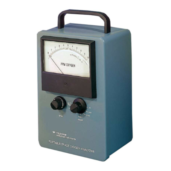
TRACE OXYGEN ANALYZER
MODEL 311-D
RANGES: 0-100 PPM; 0-1000 PPM; 1% AND 100%
TELEDYNE ANALYTICAL INSTRUMENTS
16830 CHESTNUT STREET
CITY OF INDUSTRY, CALIF. 91749
TELEPHONE: (626) 934-1500
FAX: (626) 961-2538
TWX: (910) 584-1887 TDYANYL COID
EASYLINK: 628-31862
Web: www.teledyne-ai.com
Advertisement
Table of Contents

Related Manuals for Teledyne 311-D


Summary of Contents for Teledyne 311-D
- Page 1 INSTRUCTION MANUAL TRACE OXYGEN ANALYZER MODEL 311-D RANGES: 0-100 PPM; 0-1000 PPM; 1% AND 100% TELEDYNE ANALYTICAL INSTRUMENTS 16830 CHESTNUT STREET CITY OF INDUSTRY, CALIF. 91749 TELEPHONE: (626) 934-1500 FAX: (626) 961-2538 TWX: (910) 584-1887 TDYANYL COID EASYLINK: 628-31862 Web: www.teledyne-ai.com...
-
Page 2: Table Of Contents
TABLE OF CONTENTS MODEL 311D INTRODUCTION Description Method of Analysis Outstanding Features 1.3.1 Micro-Fuel Cell 1.3.2 Reliable Calibration 1.3.3 Integral Power Supply 1.3.4 Accuracy and Response 1.3.5 Compact Packaging 1.3.6 Circuit Description SUPPORTING EQUIPMENT AND SERVICES Sampling Equipment Power Service OPERATION Introduction Calibration... -
Page 3: Model 311D
INTRODUCTION Description: The Teledyne Analytical Instruments (TAI) Model 311-D is a portable trace oxygen analyzer which can be operated without an external power source, and reliably calibrated without the use of cumbersome, questionable, “certified” calibration gases. The instrument provides for trace oxygen analysis in decade steps ranging from 0-100 to 0-1000 ppm (full scale) plus a 0-1% and 0-100% calibration range that encompasses the known oxygen concentration of atmospheric air (20.9%, or 209,000 ppm). -
Page 4: Integral Power Supply
After the electronics have been properly zeroed (a one-time factory operation), the instrument cannot produce an output indication in the absence of oxygen; therefore, the need for a “zero” standardization gas is obviated. 1.3.3 Integral Power Supply: The differential power and digital panel meter (DPM) requirements of the instrument amplifier are furnished by three internally-mounted 750 milliampere-hour nickel-cadmium batteries. -
Page 5: Circuit Description
Further disassembly may be accomplished by removing the backplate assembly from its four mounting standoffs, and laying the two separated assemblies out as illustrated on the “Analyzer Wiring Diagram”. The diagram is included among the drawings at the rear of the manual. 1.3.6 Circuit Description: A Micro-Fuel Cell (Class B-2C) is used as the transducer;... -
Page 6: Power Service
necessary or desirable, it must have a metallic diaphragm. Regulators with organic or plastic diaphragms are permeable to oxygen, and if used in the sampling system, will lead to high oxygen readings. For atmospheric pressure sampling, connect a pump and flow control valve downstream from the analyzer and draw (rather than push) the sample through the instrument. -
Page 7: Calibration Procedure
dictated by the customer’s application. If the instrument were being used to certify the oxygen content of a product for delivery, then a calibration prior to certification would certainly be in order. If, on the other hand, the instrument is being used to monitor or guard a sample, the evidence provided by the analyzer will determine when a calibration check is in order. -
Page 8: Positive Pressure Sampling
If, on the other hand, the instrument is not to be used immediately after calibration, and a low ppm oxygen gas is being employed as a purge, allow the manifold to be purged overnight, and then disconnect both male fittings. ALWAYS DISCONNECT THE SOURCE FITTING FIRST, AND IMMEDIATELY THEREAFTER, THE VENT FITTING. -
Page 9: Battery Power Supply Services
every two (2) days of continuous use. To recharge the batteries, place the range switch in the “OFF” position and connect the power cord to a convenience outlet. The integral charging circuit will automatically energize and regulate battery charging current when the switch is in the “OFF”... -
Page 10: Cell Warranty
No tools are required to replace the cell in the instrument. Simply unscrew (ccw) the plug at the bottom of the analyzer, and the cell will drop out of the manifold cavity. Remove the new cell from its package, and carefully remove the shorting clip. Do not touch the silver-colored sensing surface of the cell -- as it is covered with a delicate Teflon membrane that can be ruptured in handling. -
Page 11: Leak Testing
Disconnect cell. Move range switch to “CAL” position. Adjust P1 such that the output of A3, pin 6, measures between 0 and +0.5 mV, ideally +-.3 mV. Adjust P2 for 0 ± 1 mV at output of A2, pin 6. Verify that the offset is the same on all ranges. - Page 12 OPERATING TEMPERATURE RANGE: 30° TO 125°F. RESPONSE AND RECOVERY: AT THE SPECIFIED FLOWRATE (0.25 SCFH), THE SENSOR OUTPUT SHOULD BE, IN TEN SECONDS, WITHIN ±10% OF AN INTRODUCED GAS HAVING A CONCENTRATION OF 100 PPM OR MORE; FOR A CONCENTRATION OF LESS THAN 100 PPM, THE SENSOR OUTPUT SHOULD BE WITHIN ±10% IN SIXTY SECONDS (PROVIDED THAT THE SENSOR IS NOT ALREADY SUPERSATURATED WITH A VERY HIGHLY-CONCENTRATED GAS, AND THE INTRODUCED GAS IS NOT VERY LOW IN CONCENTRATION.
-
Page 13: On B-2C Cell Life
EFFECT OF CO2 ON B-2C CELL LIFE -11-... -
Page 14: Spare Parts List
Orders for replacement parts should include the part number (if available) model number, serial number, sales order number, and range/background of the analyzer for which the parts are intended. SEND ORDERS TO: TELEDYNE ANALYTICAL INSTRUMENTS 16830 CHESTNUT STREET CITY OF INDUSTRY, CALIF. 91749 TELEPHONE:... -
Page 15: Drawing List
DRAWING LIST MODEL 311D B-26473 PICTORAL DIAGRAM C-28339 SCHEMATIC C-26606 WIRING DIAGRAM NOTE: The MSDS on this material is available upon request through the Teledyne Environmental Health and Safety Coordinator. Contact at (626) 934-1592. -13-...