
Related Manuals for Linksys SRW2008


Summary of Contents for Linksys SRW2008
-
Page 1: User Guide
8-Port 10/100/1000 Gigabit Switch User Guide with WebView WIRED SRW2008/SRW2008P/SRW2008MP Model No. - Page 2 WebView Switches Copyright and Trademarks Specifications are subject to change without notice. Linksys is a registered trademark or trademark of Cisco Systems, Inc. and/or its affiliates in the U.S. and certain other countries. Copyright © 2006 Cisco Systems, Inc. All rights reserved.
-
Page 3: Table Of Contents
Chapter 1: Introduction Welcome What’s in this User Guide? Chapter 2: Getting to Know the Switch Overview SRW2008 - Front Panel SRW2008P, SRW2008MP - Front Panel The Back Panel Chapter 3: Connecting the Switch Overview Before You Install the Switch... - Page 4 WebView Switches VLAN Management Tab - GVRP Statistics Tab - RMON Statistics Statistics Tab - RMON History Statistics Tab - RMON Alarm Statistics Tab - RMON Events Statistics Tab - Port Utilization Statistics Tab - 802.1x Statistics Statistics Tab - GVRP Statistics ACL Tab - IP Based ACL ACL Tab - MAC Based ACL Security Tab - ACL Binding...
- Page 5 Appendix A: About Gigabit Ethernet and Fiber Optic Cabling Gigabit Ethernet Fiber Optic Cabling Appendix B: Windows Help Appendix C: Downloading using Xmodem Startup Menu Procedures Appendix D: Glossary Appendix E: Specifications SRW2008 SRW2008MP SRW2008P Appendix F: Warranty Information Appendix G: Regulatory Information Appendix H: Contact Information...
- Page 6 WebView Switches List of Figures Figure 2-1: Front Panel of the SRW2008 Figure 2-2: Front Panel of the SRW2008P Figure 2-3: Back Panel of the SRW2008P Figure 3-1: Typical Network Configuration for the SRW2008P Figure 3-2: Attach the Brackets to the Switch...
- Page 7 WebView Switches Figure 4-20: Security Settings Figure 4-21: SSL Certificate Generation Figure 4-22: SSL Certificate Figure 4-23: IP Configuration Figure 4-24: IP Address Configuration Figure 4-25: HTTP Figure 4-26: HTTPS Configuration Figure 4-27: Network Configuration Figure 4-28: Ping Test Figure 4-29: TraceRoute Test Figure 4-30: File Management Figure 4-31: Restore System Default Settings Figure 4-32: Reboot System...
- Page 8 WebView Switches Figure 5-16: VLAN Management - GVRP Figure 5-17: Statistics - RMON Statistics Figure 5-18: Statistics - RMON History Figure 5-19: RMON History Table Figure 5-20: Statistics - RMON Alarm Figure 5-21: Statistics - RMON Events Figure 5-22: RMON Events - Events Log Figure 5-23: Statistics - Port Utilization Figure 5-24: Statistics - 802.1x Statistics Figure 5-25: Statistics - GVRP Statistics...
- Page 9 WebView Switches Figure 5-46: Spanning Tree - STP Status Figure 5-47: Spanning Tree - Global STP Figure 5-48: Spanning Tree - STP Port Settings Figure 5-49: Spanning Tree - RSTP Port Settings Figure 5-50: Spanning Tree - MSTP Properties Figure 5-51: Spanning Tree - MSTP Instance Settings Figure 5-52: Spanning Tree - MSTP Interface Settings Figure 5-53: Multicast - IGMP Snooping Figure 5-54: Multicast - Bridge Multicast...
- Page 10 WebView Switches Figure C-1: Startup Menu Figure C-1: Auto-Boot Message Figure C-2: Send File Figure C-3: Download...
-
Page 11: Chapter 1: Introduction Welcome
SRW2008x. If a specific model number is mentioned, then the feature is specific to that model. The Linksys WebView Managed switch allows you to expand your network securely. Configuration of the switch is secured using SSL for Web access. User control is secured using 802.1x security using a RADIUS authentication mechanism and can also be controlled using MAC-based filtering. - Page 12 WebView Switches The SRW2008P and SRW2008MP support Automatic Load Sensing - Power control circuitry automatically detects Power over Ethernet on access point before providing power. Power feeding of Ethernet limited for fixed 10/100/1000 Base-T/TX ports. The SRW2008MP can provide maximum output power per PoE port up to 15.4W on 8 ports simultaneously.
-
Page 13: What's In This User Guide
This appendix supplies the Switch’s warranty information. • Appendix G: Regulatory Information This appendix supplies the Switch’s regulatory information. • Appendix H: Contact Information This appendix provides contact information for a variety of Linksys resources, including Technical Support. Chapter 1: Introduction What’s in this User Guide? -
Page 14: Chapter 2: Getting To Know The Switch
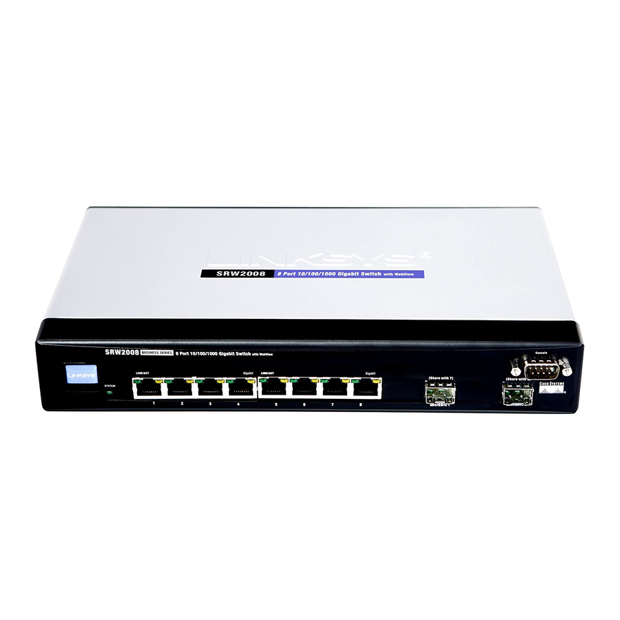
Chapter 2: Getting to Know the Switch Overview The Switches differ in number and types of LEDs and ports. The front panel of each Switch is displayed on one of the following pages. The back panel is the same on all five models. - Page 15 1000Mbps. Use the Linksys MGBT1, MGBSX1, or MGBLH1 mini-GBIC modules with the Switch. The MGBSX1 and the MGBLH1 require fiber cabling with LC connectors, while the MGBT1 requires a Category 5e Ethernet cable with an RJ-45 connector.
-
Page 16: Srw2008P, Srw2008Mp - Front Panel
Figure 2-2: Front Panel of the SRW2008P LEDs System Green. The SYSTEM LED lights up to indicate that the Switch is powered on. Link/Act Green. The LINK/ACT LED lights up to indicate a functional network link through the corresponding port (1 through 8) with an attached device. It flashes to indicate that the Switch is actively sending or receiving data over that port. -
Page 17: The Back Panel
WebView Switches Use the Linksys MGBT1, MGBSX1, or MGBLH1 mini-GBIC modules with the Switch. The MGBSX1 and the MGBLH1 require fiber cabling with LC connectors, while the MGBT1 requires a Category 5e Ethernet cable with an RJ-45 connector. Console The Console port is where you can connect a serial cable to a PC’s serial port for configuration using your PC’s HyperTerminal program. -
Page 18: Chapter 3: Connecting The Switch
WebView Switches Chapter 3: Connecting the Switch Overview This chapter will explain how to connect network devices to the Switch. For an example of a typical network configuration, see the application diagram shown below. Cable/DSL 10/100/1000 10/100 Router Internet Modem... -
Page 19: Before You Install The Switch
Placement Options Before connecting cables to the Switch, first you will physically install the Switch. Either set the Switch on its four rubber feet for desktop placement or mount the Switch in a standard-sized, 19-inch wide, 1U high rack for rack- mount placement. -
Page 20: Figure 3-2: Attach The Brackets To The Switch
To mount the Switch in any standard-sized, 19-inch wide, 1U high rack, follow these instructions: 1. Place the Switch on a hard flat surface with the front panel facing you. 2. Attach a rack–mount bracket to one side of the Switch with the supplied screws. Then attach the other bracket to the other side. -
Page 21: Figure 3-4: Proper Wall-Mount Orientation (Horizontal)
You will need two suitable screws to mount the Switch. 1. Determine where you want to mount the Switch. Ensure that the wall you use is smooth, flat, dry and sturdy and make sure the location is within reach of the power outlet. -
Page 22: Connecting The Switch
(This PC must be running the VT100 terminal emulation software, such as HyperTerminal.) 12. Connect the supplied power cord to the Switch’s power port, and plug the other end into an electrical outlet. 13. Power on the network devices connected to the Switch. Each active port’s corresponding Link/Act LED will light up on the Switch. -
Page 23: Chapter 4: Using The Console Interface For Configuration Overview
2. On the Connection Description screen, enter a name for this connection. In the example, the name of connection is SRW2008. Select an icon for the application. Then, click the OK button. 3. On the Connect To screen, select a port to communicate with the Switch: COM1, COM2, or TCP/IP. -
Page 24: Connecting To The Switch Through A Telnet Session
Flow control: None Then, click the OK button. Connecting to the Switch through a Telnet Session Open a command line editor and enter telnet 192.168.1.254. Then, press the Enter key. The Login screen will now appear. The first time you open the CLI interface, select Edit and hit Enter. Enter admin in the User Name field. -
Page 25: Configuring The Switch Through The Console Interface
WebView Switches Configuring the Switch through the Console Interface The console screens consist of a series of menus. Each menu has several options, which are listed vertically. You select a menu option when you highlight it; pressing the Enter key activates the highlighted option. -
Page 26: Figure 4-7: System Configuration Menu
4. Security Settings Figure 4-7: System Configuration Menu 5. IP Configuration 6. File Management 7. Restore System Default Settings 8. Reboot System 0. Back to main menu Chapter 4: Using the Console Interface for Configuration Configuring the Switch through the Console Interface... -
Page 27: Figure 4-8: System Information Menu
WebView Switches System Information Using this screen, you can check the Switch’s firmware versions and general system information. Figure 4-8: System Information Menu Versions The Versions screen displays the Switch’s boot, software, and hardware firmware versions. Figure 4-9: Versions General System Information The General System Information screen displays the Switch’s description, System Up Time, System MAC... -
Page 28: Figure 4-11: Management Settings Menu
Figure 4-11: Management Settings Menu Serial Port Configuration On the Serial Port Configuration screen, the Switch’s baud rate is displayed. Select Edit and press the Enter key to make changes. Toggle to the desired speed and when your changes are complete, press the Esc key to return to the Action menu. -
Page 29: Figure 4-14: Ssh Configuration
The SSH Status screen displays whether the SSH Server is enabled, the RSA and DSA key status, and any open SSH sessions. Select Refresh to update the screen if necessary. To exit, select Quit and press the Enter key. Figure 4-16: SSH Status Chapter 4: Using the Console Interface for Configuration Configuring the Switch through the Console Interface... -
Page 30: Figure 4-17: Ssh Crypto Key Generation
On the SSH Keys Fingerprints screen, the RSA and DSA keys will be displayed if they have been generated. Select Refresh to update the screen if necessary. To exit, select Quit and press the Enter key. Figure 4-18: SSH Keys Fingerprints Chapter 4: Using the Console Interface for Configuration Configuring the Switch through the Console Interface... -
Page 31: Figure 4-19: Username & Password Settings
NOTE: The Username & Password Settings screen can also be used to set passwords for other users. Figure 4-19: Username & Password Settings Security Settings The Security Settings screen enables you to configure security settings on the Switch, as well as generate and display the certificate. SSL Certificate Generation Use the Certificate Generation screen to specify a device-generated certificate. -
Page 32: Figure 4-22: Ssl Certificate
Selecting this option will prompt you to confirm that you want to disable the Active Management Profile. IP Configuration The IP Configuration screen displays these choices: the Switch’s IP Address Settings, HTTP, HTTPS Configuration and Network Configuration. IP Address Configuration... -
Page 33: Figure 4-24: Ip Address Configuration
Management VLAN. The VLAN ID number is displayed. DHCP client. The status of the DHCP client is displayed. If you want the Switch to be a DHCP client, then select ENABLE. If you want to assign an static IP address to the Switch, then enter the IP settings and select DISABLE. -
Page 34: Figure 4-27: Network Configuration
Action menu. Select Save and press the Enter key to save your changes. To exit, select Quit and press the Enter key. Figure 4-29: TraceRoute Test Chapter 4: Using the Console Interface for Configuration Configuring the Switch through the Console Interface... -
Page 35: Figure 4-30: File Management
Reboot System Select Reboot System and press the Enter key if you want to restart the Switch. You will be asked if you want to continue. Press the y key to reboot the Switch, or press the n key to cancel. After the Switch has rebooted, the Switch Main Menu screen will appear. -
Page 36: Figure 4-33: Port Status
WebView Switches Port Status On the Switch Main Menu screen, select Port Status and press the Enter key if you want to view the status information for the Switch’s ports. The Port Status screen displays the port numbers, their status, Link status, speed and duplex mode, and status of flow control, which is the flow of packet transmissions. -
Page 37: Chapter 5: Using The Web-Based Utility For Configuration
NOTE: The LEDs displayed in the Web-based Utility are not the same as the LEDs on the front panel of the Switch. The front panel LEDs display different status information, which is described in Chapter 2: Getting to Know the Switch. -
Page 38: Setup Tab - Summary
The Summary screen provides device and system information about the Switch. Device Information Host Name. Displays the name for the Switch, if one has been entered on the Setup - Network Settings tab. IP Address.The IP address of the Switch is displayed here (configurable from Setup - Network Settings tab). -
Page 39: Setup Tab - Network Settings
System Name. This field allows you to assign a system name. System Location. This field is used for entering a description of where the Switch is located, such as 3rd floor. System Contact. Enter the administrative contact person in this field. -
Page 40: Setup Tab - Time
Daylight Saving. Select Daylight Saving to enable it on the Switch. If the Switch should use US daylight savings, then select USA. If the Switch should use EU daylight savings, then select European. If it should use another kind of daylight savings, then select Custom and complete the From and To fields. -
Page 41: Port Management Tab - Port Settings
Port Management Tab - Port Settings The Port Management - Port Settings screen shows you the settings for each of the Switch’s ports. Port. The number of the port. To use an SFP module, click on the Detail button of the appropriate port (G1, G2). -
Page 42: Figure 5-6: Port Settings - Port Configuration Detail
MDI/MIDX. This is the MDI/MDIX status of the port. The MDI setting is used if the port is connected to an end station. The MDIX setting is used if the port is connected to a hub or another switch. Flow Control. This is the flow control status of the port. It is active when the port uses Full Duplex Mode. - Page 43 MDI/MDIX. Select the Auto setting if you want the port to automatically detect the cable type. Select MDI if the port is connected to an end station. Select MDIX if the port is connected to a hub or another switch.
-
Page 44: Port Management Tab - Link Aggregation
WebView Switches Port Management Tab - Link Aggregation LAG. This indicates if the port is part of a LAG. Description. Description for this LAG. Admin Status. The admin status of the LAG. Up indicates that the LAG is available. Down indicates that administrator has taken the port offline. -
Page 45: Port Management Tab - Lacp
LACP Timeout. Administrative LACP timeout. A short or Long timeout value can be selected. Long is the default. Admin Key. A channel will only be formed between ports having the same admin key. This only applies to ports located on the same switch. Chapter 5: Using the Web-based Utility for Configuration... -
Page 46: Port Management Tab - Poe Power Settings
WebView Switches Port Management Tab - PoE Power Settings NOTE: The Modify PoE Page displays the currently configured PoE ports. This option is only seen on the SRW2008P and SRW2008MP. Port. Displays the selected port’s number. Admin Status. Indicates whether PoE is enabled or disabled on the port. Priority. -
Page 47: Vlan Management Tab - Port Settings
WebView Switches VLAN Management Tab - Port Settings The VLAN Port Settings screen provides parameters for managing ports that are part of a VLAN. The port default VLAN ID (PVID) is configured on the VLAN Port Settings screen. All untagged packets arriving to the device are tagged by the ports PVID. -
Page 48: Vlan Management Tab - Ports To Vlan
WebView Switches VLAN Management Tab - Ports to VLAN The Ports to VLAN screen contains fields for configuring ports to a VLAN. The port default VLAN ID (PVID) is configured on the Create VLAN screen. All untagged packets arriving to the device are tagged by the ports PVID. The Ports to VLAN screen contains a Port Table for VLAN parameters for each ports. -
Page 49: Vlan Management Tab - Vlan To Ports
WebView Switches VLAN Management Tab - VLAN to Ports The VLAN to Ports screen contains fields for configuring VLANs to a ports. Interface. Displays the interface number. Mode. Indicates the port to VLAN mode. The possible field values are: General. Indicates the port belongs to VLANs, and each VLAN is user-defined as tagged or untagged (full 802.1Q mode). -
Page 50: Vlan Management Tab - Gvrp
WebView Switches VLAN Management Tab - GVRP GARP VLAN Registration Protocol (GVRP) is specifically provided for automatic distribution of VLAN membership information among VLAN-aware bridges. GVRP allows VLAN-aware bridges to automatically learn VLANs to bridge ports mapping, without having to individually configure each bridge and register VLAN membership. The Global System LAG information displays the same field information as the ports, but represent the LAG GVRP information. -
Page 51: Figure 5-17: Statistics - Rmon Statistics
WebView Switches Refresh Rate. Defines the amount of time that passes before the interface statistics are refreshed. The possible field values are: • No Refresh. Indicates that the RMON statistics are not refreshed. • 15 Sec. Indicates that the RMON statistics are refreshed every 15 seconds. •... -
Page 52: Statistics Tab - Rmon History
WebView Switches Collisions. Displays the number of collisions received on the interface since the device was last refreshed. Frames of xx Bytes. Number of xx-byte frames received on the interface since the device was last refreshed. Clear Counters button. This option will reset all of the statistic counts. Refresh Now button. -
Page 53: Figure 5-19: Rmon History Table
WebView Switches RMON History The RMON History screen contains interface specific statistical network samplings. Each table entry represents all counter values compiled during a single sample. History Entry No. Displays the history table entry number. Owner. Displays the RMON station or user that requested the RMON information. The field range is 0-20 characters. -
Page 54: Statistics Tab - Rmon Alarm
WebView Switches Jabbers. Displays the total number of received packets that were longer than 1518 octets. This number excludes frame bits, but includes FCS octets that had either a bad Frame Check Sequence (FCS) with an integral number of octets (FCS Error) or a bad FCS with a non-integral octet (Alignment Error) number. The field range to detect jabbers is between 20 ms and 150 ms. -
Page 55: Statistics Tab - Rmon Events
WebView Switches • Both. Indicates that both the Log and Trap mechanism are used to report alarms. Falling Threshold. Displays the falling counter value that triggers the falling threshold alarm. The falling threshold is graphically presented on top of the graph bars. Each monitored variable is designated a color. Falling Event. -
Page 56: Statistics Tab - Port Utilization
WebView Switches • None. Indicates that no event occurred. • Log. Indicates that the event is a log entry. • Trap. Indicates that the event is a trap. • Log and Trap. Indicates that the event is both a log entry and a trap. Owner. -
Page 57: Statistics Tab - 802.1X Statistics
WebView Switches Statistics Tab - 802.1x Statistics The 802.1X Statistic screen contains information about EAP packets received on a specific port. Port. Indicates the port, which is polled for statistics. Refresh Rate. Indicates the amount of time that passes before the EAP statistics are refreshed. The possible field values are: •... -
Page 58: Acl Tab - Ip Based Acl
WebView Switches • 30 Sec. Indicates that the GVRP statistics are refreshed every 30 seconds. • 60 Sec. Indicates that the GVRP statistics are refreshed every 60 seconds. The GVRP Statistics Table contains the following fields: Join Empty. Displays the device GVRP Join Empty statistics. Empty. -
Page 59: Figure 5-26: Acl - Ip Based Acl
WebView Switches Action. Indicates the action assigned to the packet matching the ACL. Packets are forwarded or dropped. In addition, the port can be shut down, a trap can be sent to the network administrator, or a packet assigned rate limiting restrictions for forwarding. - Page 60 WebView Switches Urg. Indicates the packet is urgent. Ack. Indicates the packet is acknowledged. Psh. Indicates the packet is pushed. Rst. Indicates the connection is dropped. Syn. Indicates request to start a session. Fin. Indicates request to close a session. Source Port.
-
Page 61: Acl Tab - Mac Based Acl
WebView Switches ACL Tab - MAC Based ACL The MAC Based ACL screen allows a MAC based ACL to be defined. ACEs can be added only if the ACL is not bound to an interface. ACL Name. Displays the user-defined MAC based ACLs. New ACL Name. -
Page 62: Security Tab - Acl Binding
WebView Switches Security Tab - ACL Binding When an ACL is bound to an interface, all the ACE rules that have been defined are applied to the selected interface.Whenever an ACL is assigned on a port, LAG or, VLAN, flows from that ingress interface that do not match the ACL are matched to the default rule, which is Drop unmatched packets. -
Page 63: Security Tab - Tacacs
WebView Switches Dead Time. Defines the amount of time (minutes) that a RADIUS server is bypassed for service requests. The range is 0-2000. The Dead Time default is 0 minutes. Key String. Defines the default key string used for authenticating and encrypting all RADIUS communications between the device and the RADIUS server. -
Page 64: Security Tab - 802.1X Settings
WebView Switches Timeout for Reply. Displays the amount of time that passes before the connection between the device and the TACACS+ server times out. The field range is 1-30 seconds. Status. Displays the connection status between the device and the TACACS+ server. The possible field values are: •... -
Page 65: Security Tab - Port Security
Quiet Period. Specifies the number of seconds that the switch remains in the quiet state following a failed authentication exchange (Range: 0-65535). Resending EAP. Specifies the number of seconds that the switch waits for a response to an EAP - request/ identity frame, from the supplicant (client), before resending the request. - Page 66 WebView Switches Locked port security also enables storing a list of MAC addresses in the configuration file. The MAC address list can be restored after the device has been reset. Disabled ports are activated from the Port Security page. Interface. Displays the port or LAG name. Lock Interface.
-
Page 67: Security Tab - Multiple Hosts
WebView Switches Security Tab - Multiple Hosts The Multiple Hosts screen allows network managers to configure advanced port-based authentication settings for specific ports and VLANs. Port. Displays the port number for which advanced port-based authentication is enabled. Enable Multiple Hosts. When checked, indicates that multiple hosts are enabled. Multiple hosts must be enabled in order to either disable the ingress-filter, or to use port-lock security on the selected port. -
Page 68: Qos
WebView Switches • Broadcast Only. Counts only Broadcast traffic. Rate Threshold. The maximum rate (packets per second) at which unknown packets are forwarded. The default value is 3500. The range is 70 -100000. Network traffic is usually unpredictable, and the only basic assurance that can be offered is best effort traffic delivery. -
Page 69: Qos Tab - Cos Settings
WebView Switches QoS Tab - CoS Settings The CoS Settings screen contains fields for enabling or disabling CoS. In addition, the Trust mode can be selected. The Trust mode relies on predefined fields within the packet to determine the egress queue settings. The CoS Settings screen has two areas, CoS Settings and CoS to Queue. -
Page 70: Qos Tab - Dscp Settings
WebView Switches WRR Weight. Displays the WRR weights to queues. % of WRR Bandwidth. Displays the amount of bandwidth assigned to the queue. These values are fixed and are not user defined. QoS Tab - DSCP Settings The DSCP Settings screen enables mapping DSCP values to specific queues. The DSCP Settings screen contains the following fields: DSCP. -
Page 71: Qos Tab - Basic Mode
WebView Switches Committed Burst Size (CBS). Defines CBS as the queue shaping type. The possible field value is 4096- 16,769,020 bits. The Add to List button adds the Bandwidth configuration to the Bandwidth Table at the bottom of the screen. QoS Tab - Basic Mode The Basic Mode screen contains the following fields: Trust Mode. -
Page 72: Figure 5-42: Advanced Mode - Out Of Profile Dscp
WebView Switches Out of Profile DSCP screen DSCP In. Displays the DSCP In value. DSCP Out. Displays the current DSCP out value. A new value can be selected from the pull-down menu. The Policy Settings button opens the Policy Name screen. Policy Name screen Policy Name. -
Page 73: Figure 5-45: Advanced Mode - New Aggregate Policer
WebView Switches Match. Criteria used to match IP addresses and /or MAC addresses with an ACL’s address.The possible field values are: • And. Both the MAC-based and the IP-based ACL must match a packet. • Or. Either the MAC-based or the IP-based ACL must match a packet. MAC ACL. -
Page 74: Spanning Tree
WebView Switches Spanning Tree Spanning Tree Protocol (STP) provides tree topography for any arrangement of bridges. STP also provides one path between end stations on a network, eliminating loops. Loops occur when alternate routes exist between hosts. Loops in an extended network can cause bridges to forward traffic indefinitely, resulting in increased traffic and reducing network efficiency. -
Page 75: Spanning Tree Tab - Global Stp
WebView Switches Root Hello Time (sec). Indicates the device Hello Time. The Hello Time indicates the amount of time in seconds a root bridge waits between configuration messages. The default is 2 seconds. The range is 1 to 10 seconds. Root Forward delay (sec). -
Page 76: Spanning Tree Tab - Stp Port Settings
WebView Switches • Long. Specifies 1 through 200,000,000 range for port path costs.The default path costs assigned to an interface varies according to the selected method. Bridge Settings Priority. Specifies the bridge priority value. When switches or bridges are running STP, each is assigned a priority. -
Page 77: Spanning Tree Tab - Rstp Port Settings
WebView Switches • Blocking. Indicates that the port is currently blocked and cannot forward traffic or learn MAC addresses. Blocking is displayed when Classic STP is enabled. • Listening. Indicates that the port is in Listening mode. The port cannot forward traffic nor can it learn MAC addresses. - Page 78 • Root. Provides the lowest cost path to forward packets to root switch. • Designated. Indicates that the port or LAG via which the designated switch is attached to the LAN. • Alternate. Provides an alternate path to the root switch from the root interface.
-
Page 79: Spanning Tree Tab - Mstp Properties
WebView Switches • Disabled. Disables point-to-point link. Point-to-Point Oper Status. Indicates the Point-to-Point operating state. To run a migration test, press Activate next to the Activate Protocol Migration Test field. The test sends Link Control Protocol (LCP) packets to test if a data link is enabled. Spanning Tree Tab - MSTP Properties MSTP provides differing load balancing scenarios. -
Page 80: Spanning Tree Tab - Mstp Interface Settings
WebView Switches Included VLAN. Maps the selected VLAN to the selected instance. Each VLAN belongs to one instance. Bridge Priority. Specifies the selected spanning tree instance device priority. The field range is 0-61440. Designated Root Bridge ID. Indicates the ID of the bridge with the lowest path cost to the instance ID. Root Port. - Page 81 WebView Switches Role. Indicates the port role assigned by the STP algorithm in order to provide to STP paths. The possible field values are: • Root. Provides the lowest cost path to forward packets to root device. • Designated. Indicates the port or LAG via which the designated device is attached to the LAN. •...
-
Page 82: Multicast Tab - Igmp Snooping
Leave Timeout. Indicates the amount of time the host waits, after requesting to leave the IGMP group and not receiving a Join message from another station, before timing out. If a Leave Timeout occurs, the switch notifies the Multicast device to stop sending traffic The Leave Timeout value is either user-defined, or an immediate leave value. -
Page 83: Multicast Tab - Bridge Multicast
WebView Switches Multicast Tab - Bridge Multicast The Bridge Multicast screen displays the ports and LAGs attached to the Multicast service group in the Ports and LAGs tables. The Port and LAG tables also reflect the manner in which the port or LAGs joined the Multicast group. Ports can be added either to existing groups or to new Multicast service groups. -
Page 84: Multicast Tab - Bridge Multicast Forward All
Multicast Tab - Bridge Multicast Forward All The Bridge Multicast Forward All screen contains fields for attaching ports or LAGs to a device that is attached to a neighboring Multicast router/switch. Once IGMP Snooping is enabled, Multicast packets are forwarded to the appropriate port or VLAN. -
Page 85: Snmp Tab - Views
WebView Switches SNMP Notifications. Indicates if the device can send SNMP notifications. Authentication Notifications. Indicates if SNMP Authentication failure notification is enabled on the device. SNMP Tab - Views SNMP Views provide access or block access to device features or feature aspects. For example, a view can be defined that states that SNMP Group A has Read Only (R/O) access to Multicast groups, while SNMP Group B has Read-Write (R/W) access to Multicast groups. -
Page 86: Snmp Tab - Group Profile
WebView Switches SNMP Tab - Group Profile The Group Profile screen provides information for creating SNMP groups and assigning SNMP access control privileges to SNMP groups. Groups allow network managers to assign access rights to specific device features, or features aspects. Group Name. -
Page 87: Snmp Tab - Group Membership
WebView Switches SNMP Tab - Group Membership The Group Membership screen provides information for assigning SNMP access control privileges to SNMP groups. User name. Provides a user-defined local user list. Engine ID. Indicates either the local or remote SNMP entity to which the user is connected. Changing or removing the local SNMP Engine ID deletes the SNMPv3 User Database. -
Page 88: Snmp Tab - Communities
WebView Switches The Add to List button adds the Group Membership configuration to the respective table at the bottom of the screen. SNMP Tab - Communities The Communities screen contains three areas, Communities, Basic Table and Advanced Table. SNMP Management Station. Defines the management station IP address for which the advanced SNMP community is defined. -
Page 89: Snmp Tab - Notification Filter
WebView Switches Community String — Displays the password used to authenticate the management station to the device. Access Mode — Displays the access rights of the community. View Name — Displays the user-defined SNMP view. Advanced Table Management Station — Displays the management station IP address for which the basic SNMP community is defined. -
Page 90: Snmp Tab - Notification Recipient
WebView Switches SNMP Tab - Notification Recipient The Notification Recipient screen contains information for defining filters that determine whether traps are sent to specific users, and the trap type sent. SNMP notification filters provide the following services: • Identifying Management Trap Targets •... -
Page 91: Admin Tab - User Authentication
WebView Switches • Authentication. Indicates the packet is authenticated. • Privacy. Indicates the packet is both authenticated and encrypted. UDP Port. Displays the UDP port used to send notifications. The default is 162. Filter Name. Indicates if the SNMP filter for which the SNMP Notification filter is defined. Timeout. -
Page 92: Admin Tab - Jumbo Frames
Admin Tab - Static Address A static address can be assigned to a specific interface on this switch. Static addresses are bound to the assigned interface and cannot be moved. When a static address is seen on another interface, the address will be ignored and will not be written to the address table. -
Page 93: Admin Tab - Dynamic Address
The Dynamic Address Table contains the MAC addresses learned by monitoring the source address for traffic entering the switch. When the destination address for inbound traffic is found in the database, the packets intended for that address are forwarded directly to the associated port. Otherwise, the traffic is flooded to all ports. -
Page 94: Admin Tab - Logging
WebView Switches Admin Tab - Logging The System Logs enable viewing device events in real time, and recording the events for later usage. System Logs record and manage events and report errors or informational messages. Event messages have a unique format, as per the SYSLOG protocols recommended message format for all error reporting. -
Page 95: Admin Tab - Port Mirroring
Port mirroring can be used as diagnostic tool and/or a debugging feature. Port mirroring also enables switch performance monitoring. Network administrators configure port mirroring by selecting a specific port to copy all packets, and different ports from which the packets are copied. -
Page 96: Admin Tab - Save Configuration
3. Reset the device now. Via TFTP Upgrade. Select this option to upgrade the switch from a file located on a TFTP server. • TFTP Server. The TFTP Server IP Address that contains the source file to upgrade from. • Source File. Specifies the name of the upgrade file on the TFTP Server. -
Page 97: Admin Tab - Firmware Upgrade
WebView Switches Admin Tab - Firmware Upgrade The Firmware Upgrade screen contains the following fields: via TFTP. Defines the upgrade through a TFTP Server. via HTTP. Allows you to upgrade the firmware using your Web browser. Upgrade. Defines the screen functionality as a Firmware upgrade. Backup. -
Page 98: Admin Tab - Factory Defaults
The Factory Reset screen allows network managers to reset the device to the factory defaults shipped with the switch. Restoring factory defaults results in erasing the configuration file. NOTE: Restoring the factory defaults will erase all configuration settings that you have made. -
Page 99: Admin Tab - Memory Logs
WebView Switches Admin Tab - Memory Logs The Memory Log screen contains all system logs in a chronological order that are saved in RAM (Cache). Log Index. Displays the log number. Log Time. Displays the time at which the log was generated. Severity. -
Page 100: Appendix A: About Gigabit Ethernet And Fiber Optic Cabling
A fiber connection always require two fiber cables: one transmits data, and the other receives it. Each fiber optic cable is tipped with a connector that fits into a fiber port on a network adapter, hub, or switch. In the USA, most cables use a square SC connector that slides and locks into place when plugged into a port or connected to another cable. -
Page 101: Appendix B: Windows Help
WebView Switches Appendix B: Windows Help Almost all networking products require Microsoft Windows. Windows is the most used operating system in the world and comes with many features that help make networking easier. These features can be accessed through Windows Help and are described in this appendix. TCP/IP Before a computer can communicate within a network, TCP/IP must be enabled. -
Page 102: Appendix C: Downloading Using Xmodem
Switch. 3. Power on your computer and launch HyperTerminal, follow the instructions in Chapter 4: Using the Console Interface for Configuration to configure HyperTerminal to connect to the Switch. 4. Power on the Switch and watch for the auto-boot message: Autoboot in 2 seconds - press RETURN or Esc. -
Page 103: Figure C-2: Send File
8. In the Filename: field, enter the file path for the file to be downloaded or click Browse to locate the file. Only valid files, with a *.ros or *.rfb suffix, that have been provided by Linksys, can be downloaded. -
Page 104: Appendix D: Glossary
This glossary contains some basic networking terms you may come across when using this product. For more advanced terms, see the complete Linksys glossary at http://www.linksys.com/glossary. Access Mode - Specifies the method by which user access is granted to the system. - Page 105 WebView Switches Bandwidth - The transmission capacity of a given device or network. Bandwidth Assignments - Indicates the amount of bandwidth assigned to a specific application, user, and/or interface. Baud - Indicates the number of signaling elements transmitted each second. Best Effort - Indicates that traffic is assigned to the lowest priority queue, and packet delivery is not guaranteed.
- Page 106 WebView Switches Combo Ports - A single logical port with two physical connections, including an RJ-45 connection and a SFP connection. Communities - Specifies a group of users which retain the same system access rights. CoS (Class of Service) - The 802.1p priority scheme. CoS provides a method for tagging packets with priority information.
- Page 107 ICMP (Internet Control Message Protocol) - Allows the gateway or destination host to communicate with the source host. For example, to report a processing error. IGMP (Internet Group Management Protocol) - Allows hosts to notify their local switch or router that they want to receive transmissions assigned to a specific multicast group.
- Page 108 WebView Switches LAN - The computers and networking products that make up your local network. MAC (Media Access Control) Address - The unique address that a manufacturer assigns to each networking device. Mask - A filter that includes or excludes certain values, for example parts of an IP address. Mbps (MegaBits Per Second) - One million bits per second;...
- Page 109 For example, all devices with a prefix of 157.100.100.100 are part of the same subnet. Subnet Mask - An address code that determines the size of the network. Switch - Filters and forwards packets between LAN segments. Switches support any packet protocol type. Appendix D: Glossary...
- Page 110 WebView Switches TACACS+ (Terminal Access Controller Access Control System Plus) - Proprietary Cisco enhancement to Terminal Access Controller Access Control System (TACACS). Provides additional support for authentication, authorization, and accounting. TCP (Transmission Control Protocol) - A network protocol for transmitting data that requires acknowledgement from the recipient of data sent.
-
Page 111: Appendix E: Specifications
WebView Switches Appendix E: Specifications SRW2008 Model SRW2008 Ports 8 RJ-45 connectors for 10BASE-T/100BASE-TX/1000Base-T with 2 shared SFP ports on port 7 and 8 (combo port) Console port Auto MDI/MDI-X Autonegotiate/Manual setting Cabling Type UTP CAT 5 or better for 10BASE-T/100BASE-TX, UTP CAT 5e or better for 1000BASE-T... - Page 112 Secure Shell (SSH) RADIUS port mirroring TFTP upgrade SSL security for Web UI DHCP Client BootP SNTP Xmodem upgrade Cable Diagnostics PING Telnet Client (SSH secure support) Security IEEE 802.1x 802.1x - RADIUS Authentication. MD5 Encryption Appendix E: Specifications SRW2008...
- Page 113 IGMP (v1/v2) snooping limits bandwidth-intensive video traffic to only the requestors. Support 256 multicast groups. Priority levels 4 Hardware queues Scheduling Priority Queueing and Weighted Round Robin (WRR) Class of Service Port-based 802.1p VLAN priority based IPv4/v6 IP Precedence/TOS/DSCP based TCP/UDP port based Diffserv Classification and Remarking ACLs Appendix E: Specifications SRW2008...
- Page 114 FCC Part15 Class A, CE Class A, UL, cUL, CE mark, CB Operating Temp. 0º to 40ºC (32º to 104ºF) Storage Temp. -20º to 70ºC (-4º to 158ºF) Operating Humidity 10% to 90% Storage Humidity 10% to 95% Appendix E: Specifications SRW2008...
-
Page 115: Srw2008Mp
WebView Switches SRW2008MP Ports 8 RJ-45 connectors for 10BASE-T/100BASE-TX/1000Base-T with 2 shared SFP ports on port 7 and 8 (combo port) Console port Auto MDI/MDI-X Autonegotiate/Manual setting Cabling Type UTP CAT 5 or better for 10BASE-T/100BASE-TX, UTP CAT 5e or better for 1000BASE-T LEDs Link/Act, PoE, System 802.3af compliant. - Page 116 WebView Switches SNMP MIBs RFC1213 MIB-2, RFC2863 Interface MIB, RFC2665 Ether-like MIB, RFC1493 Bridge MIB, RFC2674 Extended Bridge MIB (P-bridge, Q-bridge), RFC2819 RMON MIB (groups 1,2,3,9 only), RFC2737 Entity MIB, RFC 2618 RADIUS Client MIB RFC 1215 Traps RMON Embedded Remote Monitoring (RMON) software agent supports four RMON groups (history, statistics, alarms, and events) for enhanced traffic management, monitoring, and analysis.
- Page 117 WebView Switches Source and Destination IP address Protocol TOS/DSCP Port VLAN Ethertype Availability Link Aggregation Link Aggregation using IEEE 802.3ad LACP Up to 8 ports in up to 8 groups Storm Control Broadcast, Muticast and Unknown Unicast Spanning Tree IEEE 802.1D Spanning Tree, IEEE 802.1w Rapid Spanning Tree, IEEE 802.1s Multiple Spanning Tree IGMP Snooping IGMP (v1/v2) snooping limits bandwidth-intensive video traffic to only the requestors.
- Page 118 WebView Switches Standards 802.3 10BASE-T Ethernet, 802.3u 100BASE-TX Fast Ethernet, 802.3ab 1000BASE-T Gigabit Ethernet, 802.3z Gigabit Ethernet, 802.3x Flow Control, 802.3 ad LACP,802.3af POE, 802.1d STP, 802.1Q/p VLAN, 802.1w Rapid STP, 802.1s Multiple STP, 802.1x Port Access Authentication Environmental Dimensions 11”...
-
Page 119: Srw2008P
WebView Switches SRW2008P Ports 8 RJ-45 connectors for 10BASE-T/100BASE-TX/1000Base-T with 2 shared SFP ports on port 7 and 8 (combo port) Console port Auto MDI/MDI-X Autonegotiate/Manual setting Cabling Type UTP CAT 5 or better for 10BASE-T/100BASE-TX, UTP CAT 5e or better for 1000BASE-T LEDs Link/Act, PoE, System 802.3af complaint. - Page 120 WebView Switches SNMP SNMP version 1, 2c with support for traps1,2c,3 with support for traps. SNMP MIBs RFC1213 MIB-2, RFC2863 Interface MIB, RFC2665 Ether-like MIB, RFC1493 Bridge MIB, RFC2674 Extended Bridge MIB (P-bridge, Q-bridge), RFC2819 RMON MIB (groups 1,2,3,9 only), RFC2737 Entity MIB, RFC 2618 RADIUS Client MIB RFC 1215 Traps RMON Embedded Remote Monitoring (RMON) software agent supports four RMON groups (history, statistics, alarms, and events)
- Page 121 WebView Switches Source and Destination IP address Protocol TOS/DSCP Port VLAN Ethertype Availability Link Aggregation Link Aggregation using IEEE 802.3ad LACP Up to 8 ports in up to 8 groups Storm Control Broadcast, Muticast and Unknown Unicast Spanning Tree IEEE 802.1D Spanning Tree, IEEE 802.1w Rapid Spanning Tree, IEEE 802.1s Multiple Spanning Tree IGMP Snooping IGMP (v1/v2) snooping limits bandwidth-intensive video traffic to only the requestors.
- Page 122 WebView Switches Standards 802.3 10BASE-T Ethernet, 802.3u 100BASE-TX Fast Ethernet, 802.3ab 1000BASE-T Gigabit Ethernet, 802.3z Gigabit Ethernet, 802.3x Flow Control, 802.3 ad LACP,802.3af POE, 802.1d STP, 802.1Q/p VLAN, 802.1w Rapid STP, 802.1s Multiple STP, 802.1x Port Access Authentication Environmental Dimensions 11”...
-
Page 123: Appendix F: Warranty Information
Your exclusive remedy and Linksys' entire liability under this warranty will be for Linksys at its option to repair or replace the Product or refund Your purchase price less any rebates. -
Page 124: Appendix G: Regulatory Information
WebView Switches Appendix G: Regulatory Information FCC Statement This product has been tested and complies with the specifications for a Class B digital device, pursuant to Part 15 of the FCC Rules. These limits are designed to provide reasonable protection against harmful interference in a residential installation. - Page 125 Equipment (WEEE) This document contains important information for users with regards to the proper disposal and recycling of Linksys products. Consumers are required to comply with this notice for all electronic products bearing the following symbol: Appendix G: Regulatory Information...
- Page 126 WebView Switches Appendix G: Regulatory Information...
- Page 127 WebView Switches Appendix G: Regulatory Information...
- Page 128 WebView Switches Appendix G: Regulatory Information...
- Page 129 WebView Switches For more information, visit www.linksys.com. Appendix G: Regulatory Information...
-
Page 130: Appendix H: Contact Information
Can't find information about a product you want to buy on the web? Do you want to know more about networking with Linksys products? Give our advice line a call at: Or fax your request in to: If you experience problems with any Linksys product,...