
Related Manuals for Linksys SRW2024P


Summary of Contents for Linksys SRW2024P
- Page 1 USER GUIDE 24-Port 10/100/1000 Gigabit Switch BUSINESS SERIES with Webview and PoE Model No. SRW2024P WIRED Model No. Model No. Model No. Model No.
- Page 2 WebView Switches Copyright and Trademarks Specifications are subject to change without notice. Linksys is a registered trademark or trademark of Cisco Systems, Inc. and/or its affiliates in the U.S. and certain other countries. Copyright © 2006 Cisco Systems, Inc. All rights reserved.
-
Page 3: Table Of Contents
24-Port 10/100/1000 Gigabit Switch with Webview and PoE Table of Contents Chapter 1: Introduction Welcome Chapter 2: Getting to Know the Switch Front Panel The Back Panel The Side Panel LAN Ports The Gigabit Expansion Ports The Console Port Chapter 3: Connecting the Switch Overview Before You Install the Switch... - Page 4 24-Port 10/100/1000 Gigabit Switch with Webview and PoE VLAN Management Tab - Ports to VLAN VLAN Management Tab - VLAN to Ports Statistics Tab - RMON Statistics Statistics Tab - RMON History Statistics Tab - RMON Alarm Statistics Tab - RMON Events Statistics Tab - Port Utilization Statistics Tab - 802.1x Statistics...
- Page 5 24-Port 10/100/1000 Gigabit Switch with Webview and PoE Admin Tab - Cable Test Admin Tab - Save Configuration Admin Tab - Jumbo Frame Admin Tab - Reboot Admin Tab - Factory Default Appendix A: About Gigabit Ethernet and Fiber Optic Cabling...
- Page 6 Figure 2-1: Front Panel Figure 2-2: Back Panel Figure 2-3: Side Panel Figure 3-1: Typical Network Configuration for the SRW2024P Figure 3-2: Attach the Brackets to the Switch Figure 3-3: Mount the Switch in the Rack Figure 4-1: Finding HyperTerminal...
- Page 7 24-Port 10/100/1000 Gigabit Switch with Webview and PoE Figure 4-23: Port Status Figure 4-24: Port Configuration Figure 4-25: System PoE Configuration Figure 4-26: Power Configuration Figure 4-27: Power Port Status Figure 4-28: Port PoE Configuration Figure 4-29: Help Figure 4-30: Log Out...
- Page 8 24-Port 10/100/1000 Gigabit Switch with Webview and PoE Figure 5-23: Statistics - Port Utilization Figure 5-24: Statistics - 802.1x Statistics Figure 5-25: ACL - IP Based ACL Figure 5-26: ACL - Mac Based ACL Figure 5-27: Security - ACL Binding Figure 5-28: Security - Athentication Servers Figure 5-29: Security - 802.1x Settings...
- Page 9 24-Port 10/100/1000 Gigabit Switch with Webview and PoE Figure 5-52: Admin - Forwarding Database Figure 5-53: Admin - SNMP Figure 5-54: Admin - Log Figure 5-55: Admin - Log - Flash Logging Figure 5-56: Admin - Log - Memory Logging...
-
Page 10: Chapter 1: Introduction
Chapter 1: Introduction Welcome The Linksys WebView Managed Switch allows you to expand your network securely. Configuration of the switch is secured using SSL for Web access. User control is secured using 802.1x security using a RADIUS authentication mechanism and can also be controlled using MAC-based filtering. - Page 11 This appendix supplies the Switch’s warranty information. • Appendix G: Regulatory Information This appendix supplies the Switch’s regulatory information. • Appendix H: Contact Information This appendix provides contact information for a variety of Linksys resources, including Technical Support. Chapter 1: Introduction Welcome...
-
Page 12: Chapter 2: Getting To Know The Switch
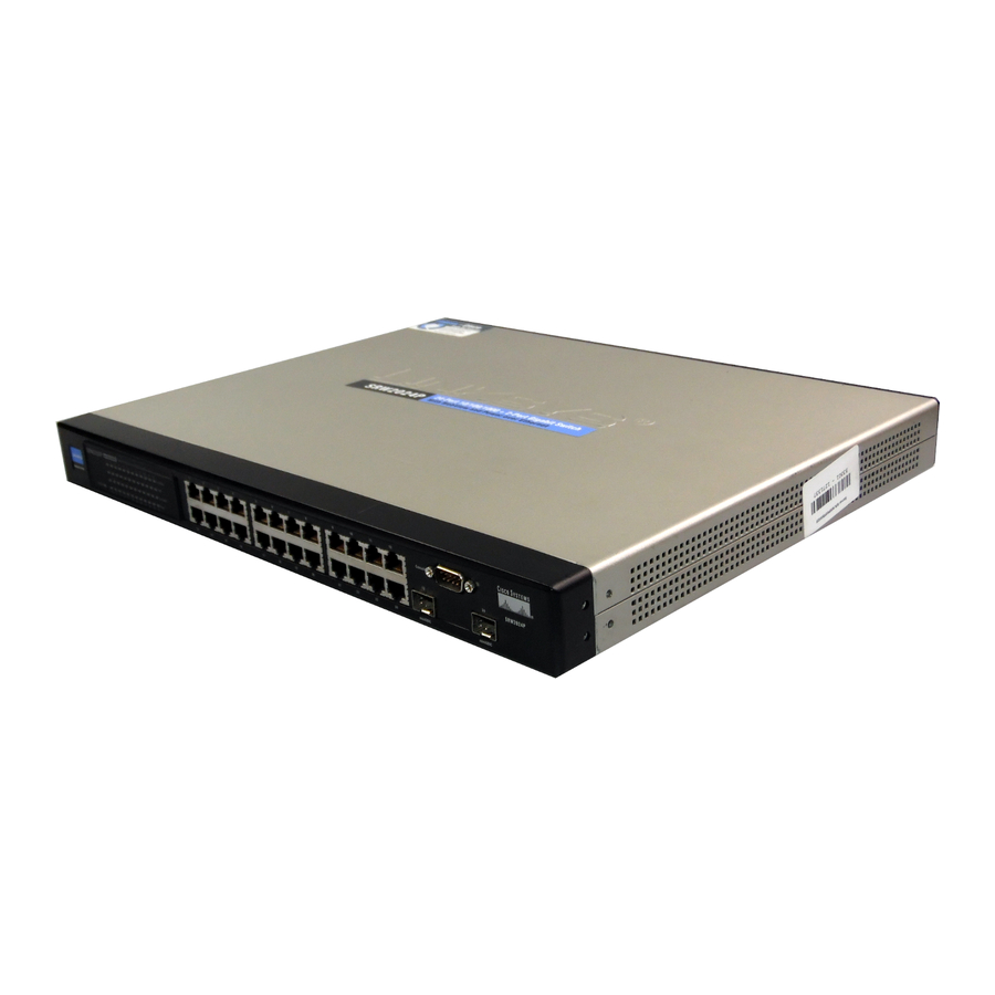
Figure 2-1: Front Panel LEDs System Green. The System LED lights green to indicate the power is being supplied to the Switch. Lights orange to indicate that the Switch’s power-on-self-test (POST) is in progress. Flashes orange to indicate that the POST has failed. -
Page 13: The Back Panel
LAN port (12 and/or 24) cannot be used. They link to high-speed network peripheral system or clients at speeds of 1000Mbps. Use the Linksys MGBT1, MGBSX1, or MGBLH1 miniGBIC modules with the Switch. The MGBSX1 and the MGBLH1 require fiber cabling with LC connectors, while the MGBT1 requires a Category 5e Ethernet cable with an RJ-45 connector. -
Page 14: The Side Panel
802.3af-compliant device, the Switch automatically senses the load and dynamically supplies the required power. The Switch delivers power to a device using the two data wire pairs in the twisted-pair cable. Each port can provide up to 15.4 W of power at the standard -48 VDC voltage.To connect a device to a port, you will need to use Category 5 (or better) network cable. -
Page 15: The Console Port
(for configuration purposes) using the provided serial cable. You can use HyperTerminal to manage the Switch using the console port. With this and many other Linksys products, your networking options are limitless. Go to the Linksys website at www.linksys.com for more information about products that work with the Switch. -
Page 16: Chapter 3: Connecting The Switch
Chapter 3: Connecting the Switch Overview This chapter will explain how to connect network devices to the Switch. For an example of a typical network configuration, see the application diagram shown below. Figure 3-1: Typical Network Configuration for the SRW2024P When you connect your network devices, make sure you don’t exceed the maximum cabling distances, which are... -
Page 17: Before You Install The Switch
• Keep cabling away from sources of electrical noise, power lines, and fluorescent lighting fixtures. • Position the Switch away from water and moisture sources. • To ensure adequate air flow around the Switch, be sure to provide a minimum clearance of two inches (50 mm). -
Page 18: Placement Options
Placement Options Before connecting cables to the Switch, first you will physically install the Switch. Either set the Switch on its four rubber feet for desktop placement or mount the Switch in a standard-sized, 19-inch wide, 1U high rack for rack- mount placement. -
Page 19: Uplinking The Switch
Uplinking the Switch To uplink the Switch, connect one end of a Category 5 (or better) Ethernet network cable into one of the 24 gigabit ports, and then connect the other end of the cable into the peripheral device’s uplink port. MDI/MDIX will automatically detect the speed and cable type. -
Page 20: Chapter 4: Using The Console Interface For Configuration
SRW2048P. Select an icon for the application. Then, click the OK button. 3. On the Connect To screen, select a port to communicate with the Switch: COM1, COM2, or TCP/IP. Chapter 4: Using the Console Interface for Configuration... -
Page 21: Connecting To The Switch Through A Telnet Session
24-Port 10/100/1000 Gigabit Switch with Webview and PoE 4. Set the serial port settings as follows: Bits per second: 38400 Data bits: 8 Parity: None Stop bits: 1 Flow control: None Then, click the OK button. Connecting to the Switch through a Telnet Session Open a command line editor and enter telnet 192.168.1.254. -
Page 22: Configuring The Switch Through The Console Interface
24-Port 10/100/1000 Gigabit Switch with Webview and PoE Configuring the Switch through the Console Interface The console screens consist of a series of menus. Each menu has several options, which are listed vertically. You select a menu option when you highlight it; pressing the Enter key activates the highlighted option. -
Page 23: Figure 4-7: System Configuration Menu
24-Port 10/100/1000 Gigabit Switch with Webview and PoE System Configuration Menu On the System Configuration Menu screen, you have these choices: 1. System Information 2. Management Settings 3. User & Password Settings 4. IP Configuration 5. File Management 6. Restore System Default Settings Figure 4-7: System Configuration Menu 7. -
Page 24: Figure 4-8: System Information Menu
Figure 4-9: Versions General Information The General System Information screen displays the Switch’s description, System Up Time, System MAC Address, System Contact, System Name, and System Location. Select Edit and press the Enter key to make changes. When your changes are complete, press the Esc key to return to the Action menu. -
Page 25: Figure 4-11: Management Settings Menu
Figure 4-11: Management Settings Menu Serial Port Configuration On the Serial Port Configuration screen, the Switch’s baud rate is displayed. Select Edit and press the Enter key to make changes. Toggle to the desired speed and when your changes are complete, press the Esc key to return to the Action menu. -
Page 26: Figure 4-13: User & Password Settings
VLAN through which you can gain management access to the Switch. By default, all ports on the Switch are members of VLAN 1, so a management station can be connected to any port on the Switch. If other VLANs are configured and you change the Management VLAN, you may lose management access to the Switch. -
Page 27: Figure 4-16: Http/Https
HTTP Server port. Set the TCP port that HTTP packets are sent and received from. HTTPS Server. Enable or disable the Secure HTTP server function of the Switch. HTTPS Server port. Set the TCP port that the HTTPS packets are sent and received from. -
Page 28: Figure 4-18: Ping Test
24-Port 10/100/1000 Gigabit Switch with Webview and PoE Network Diagnostics The Network Configuration Screen allows you to use Ping to test network connectivity. The Ping screen displays the IP address of the location you want to contact. Select Edit to change the IP address, and select Execute to begin the ping test. -
Page 29: Figure 4-20: Restore System Default Settings
Reboot System Select Reboot System and press the Enter key if you want to restart the Switch. You will be asked if you want to continue. Press the y key to reboot the Switch, or press the n key to cancel. After the Switch has rebooted, the Switch Main Menu screen will appear. -
Page 30: Figure 4-23: Port Status
24-Port 10/100/1000 Gigabit Switch with Webview and PoE Port Status On the Switch Main Menu screen, select Port Status and press the Enter key if you want to view the status information for the Switch’s ports. The Port Status screen displays the port numbers, their status, Link status, speed and duplex mode, and status of flow control, which is the flow of packet transmissions. -
Page 31: Figure 4-25: System Poe Configuration
Speed/Duplex. Allows manual selection of port speed and duplex mode (that is, with auto-negotiation disabled). Flow Control. Allows automatic or manual selection of flow control. PoE Configuration On the Switch Main Menu screen, select PoE Configuration and press the Enter key if you want to configure the Switch’s ports. PoE Main Menu... -
Page 32: Figure 4-28: Port Poe Configuration
24-Port 10/100/1000 Gigabit Switch with Webview and PoE ports and later the power demands on the Switch fall back within its budget, the dropped power is automatically restored. Port PoE Configuration The Power Port Configuration screen allows you to set the PoE settings for each port. Select the Edit action and use the left-right and up-down arrows to select the attribute you would like to set. - Page 33 24-Port 10/100/1000 Gigabit Switch with Webview and PoE Chapter 4: Using the Console Interface for Configuration Configuring the Switch through the Console Interface...
-
Page 34: Chapter 5: Using The Web-Based Utility For Configuration
NOTE: The LEDs displayed in the Web-based Utility are not the same as the LEDs on the front panel of the Switch. The front panel LEDs display different status information, which is described in Chapter 2: Getting to Know the Switch. -
Page 35: Setup Tab - Summary
The Summary screen provides device and system information about the Switch. Device Information System Name. Displays the name for the Switch, if one has been entered on the Setup - Network Settings tab. IP Address.The IP address of the Switch is displayed here (configurable from Setup - Network Settings tab). -
Page 36: Setup Tab - Network Settings
System Name. This field allows you to assign a system name. System Location. This field is used for entering a description of where the Switch is located, such as 3rd floor. System Contact. Enter the administrative contact person in this field. -
Page 37: Setup Tab - Time
Maintaining an accurate time on the Switch enables the system log to record meaningful dates and times for event entries. If the clock is not set, the Switch will only record the time from the factory default set at the last bootup. -
Page 38: Port Management Tab - Port Settings
Daylight Savings. Select Daylight Savings to enable it on the Switch. If the Switch should use US daylight savings, then select USA. If the Switch should use EU daylight savings, then select European. If it should use another kind of daylight savings, then select Custom and complete the From and To fields. -
Page 39: Figure 5-6: Port Settings - Port Setting Detail
MDI/MIDX. This is the MDI/MDIX status of the port. The MDI setting is used if the port is connected to an end station. The MDIX setting is used if the port is connected to a hub or another switch. Flow Control. This is the flow control status of the port. It is active when the port uses Full Duplex Mode. -
Page 40: Port Management Tab - Link Aggregation
Flow Control. Enables flow control. Flow control can eliminate frame loss by “blocking” traffic from end stations or segments connected directly to the Switch when its buffers fill. When enabled, back pressure is used for half- duplex operation and IEEE 802.3x for full-duplex operation. (Avoid using flow control on a port connected to a hub unless it is actually required to solve a problem. -
Page 41: Figure 5-7: Port Management - Link Aggregration
24-Port 10/100/1000 Gigabit Switch with Webview and PoE Type. The type of LAG is displayed here. Link Status. The link status is displayed here. Speed. The connection speed is displayed here. Duplex. The connection duplex is displayed here. Flow Control. This is the flow control status of the LAG. It is active when the port uses Full Duplex Mode. -
Page 42: Port Management Tab - Lacp
Cisco EtherChannel standard. For dynamic LAGs, the switches have to comply with LACP. This Switch supports up to eight LAGs. For example, a LAG consisting of two 1000 Mbps ports can support an aggregate bandwidth of 4 Gbps when operating at full duplex. -
Page 43: Port Management Tab - Poe Power Settings
Port Management Tab - PoE Power Settings If a device is connected to a Switch port and the Switch detects that it requires more than the power budget of the port, no power is supplied to the device (that is, port power remains off). -
Page 44: Vlan Management Tab - Create Vlan
24-Port 10/100/1000 Gigabit Switch with Webview and PoE VLAN Management Tab - Create VLAN The Create VLAN screen provides information and global parameters for configuring and working with VLANs. Single VLAN VLAN ID (2-4094). Indicates the ID number of the VLAN being configured. Up to 256 VLANs can be created. This field is used to add VLANs one at a time. -
Page 45: Vlan Management Tab - Ports To Vlan
24-Port 10/100/1000 Gigabit Switch with Webview and PoE Acceptable Frame Type. Packet type accepted on the port. Possible values are: • Admit Tag Only. Indicates that only tagged packets are accepted on the port. • Admit All. Indicates that both tagged and untagged packets are accepted on the port. -
Page 46: Vlan Management Tab - Vlan To Ports
24-Port 10/100/1000 Gigabit Switch with Webview and PoE Untagged. Packets forwarded by the interface are untagged. Tagged. Defines the interface as a tagged member of a VLAN. All packets forwarded by the interface are tagged. The packets contain VLAN information. -
Page 47: Statistics Tab - Rmon Statistics
24-Port 10/100/1000 Gigabit Switch with Webview and PoE Statistics Tab - RMON Statistics The RMON Statistics screen contains fields for viewing information about device utilization and errors that occurred on the device. To view the interface statistics for a port, select the required interface from the drop-down menu and click Query. -
Page 48: Statistics Tab - Rmon History
24-Port 10/100/1000 Gigabit Switch with Webview and PoE CRC & Align Errors. Displays the number of CRC and Align errors that have occurred on the interface since the device was last refreshed. Undersize Packets. Displays the number of undersized packets (less than 64 octets) received on the interface since the device was last refreshed. -
Page 49: Statistics Tab - Rmon Alarm
24-Port 10/100/1000 Gigabit Switch with Webview and PoE Sampling Interval. Indicates (in seconds) the time that samplings are taken from the ports. The field range is 1- 3600. The default is 1800 seconds (30 minutes). Sampling Requested. Indicates the number of samples to save. (Range:1-65535) Owner. - Page 50 24-Port 10/100/1000 Gigabit Switch with Webview and PoE Sample Type. Defines the sampling method for the selected variable and comparing the value against the thresholds. The possible field values are: • Absolute. Compares the values directly with the thresholds at the end of the sampling interval.
-
Page 51: Statistics Tab - Rmon Events
24-Port 10/100/1000 Gigabit Switch with Webview and PoE • Both. Indicates that both the Log and Trap mechanism are used to report alarms. Owner. Displays the device or user that defined the alarm. The Add button adds the entry to the RMON Alarms Table. -
Page 52: Statistics Tab - Port Utilization
24-Port 10/100/1000 Gigabit Switch with Webview and PoE Statistics Tab - Port Utilization The Port Utilization screen displays the amount of resources each interface is currently consuming. Ports in green are functioning normally, while ports in red are currently transmitting an excessive amount of network traffic. -
Page 53: Acl Tab - Ip Based Acl
24-Port 10/100/1000 Gigabit Switch with Webview and PoE Packet. Displays the amount of packets measured for the particular 802.1x statistic. ACL Tab - IP Based ACL The IP Based ACL (Access Control List) screen contains information for defining IP Based ACLs. Access Control Lists (ACL) provide packet filtering for IP frames (based on address, protocol, Layer 4 protocol port number or TCP control code) or any frames (based on MAC address or Ethernet type). - Page 54 24-Port 10/100/1000 Gigabit Switch with Webview and PoE • OSPF. Matches the packet to the Open Shortest Path First (OSPF) protocol. • UDP. Indicates that the User Datagram Protocol is used to classify network flows. • Protocol ID To Match. Adds user-defined protocols to which packets are matched to the ACE. Each protocol has a specific protocol number which is unique.
-
Page 55: Acl Tab - Mac Based Acl
24-Port 10/100/1000 Gigabit Switch with Webview and PoE Dest. IP Address. Matches the destination port IP address to which packets are addressed to the ACE. Wildcard Mask. Defines the destination IP address wildcard mask. Match DSCP. Matches the packet DSCP value to the ACE. Either the DSCP value or the IP Precedence value is used to match packets to ACLs. -
Page 56: Security Tab - Acl Binding
You must configure a mask for an ACL rule before you can bind it to a port. This Switch only supports ACLs for ingress filtering. You can only bind one IP or one MAC ACL to any port, for ingress filtering. -
Page 57: Security Tab - Authentication Servers
When a client (i.e., Supplicant) connects to a switch port, the Switch (i.e., Authenticator) responds with an EAPOL identity request. The client provides its identity (such as a user name) in an EAPOL response to the Switch, which it forwards to the RADIUS server. The RADIUS server verifies the client identity and sends an access challenge back to the client. -
Page 58: Security Tab - 802.1X Settings
• Each client that needs to be authenticated must have dot1X client software installed and properly configured. • The RADIUS server and 802.1X client support EAP. (The Switch only supports EAPOL in order to pass the EAP packets from the server to the client.) •... -
Page 59: Figure 5-1: Security - 802.1X Settings - Port Settings
(Range: 1-10; Default 2) Quiet Period. Sets the time that a switch port waits after the Max Request Count has been exceeded before attempting to acquire a new client. (Range: 1-65535 seconds; Default: 60 seconds) Reauthentication Period. -
Page 60: Security Tab - Ports Security
Security Tab - Ports Security Port security is a feature that allows you to configure a switch port with one or more device MAC addresses that are authorized to access the network through that port. When port security is enabled on a port, the Switch stops learning new MAC addresses on the specified port when it has reached a configured maximum number. -
Page 61: Security Tab - Https Settings
If anyone tries to access a management interface on the Switch from an invalid address, the Switch will reject the connection, enter an event message in the system log, and send a trap message to the trap manager. -
Page 62: Security Tab - Ssh Settings
SSH Server-Key Size. Specifies the SSH server key size. The server key is a private key that is never shared outside the Switch.The host key is shared with the SSH client, and is fixed at 1024 bits. (Range: 512-896 bits;... -
Page 63: Ssh Host-Key Settings
(Version 1), DSA (Version 2), Both: Default: RSA) The SSH server uses RSA or DSA for key exchange when the client first establishes a connection with the Switch, and then negotiates with the client to select either DES (56- bit) or 3DES (168-bit) for data encryption. -
Page 64: Qos Tab
Class of Service (CoS) allows you to specify which data packets have greater precedence when traffic is buffered in the Switch due to congestion. The Switch supports CoS with four priority queues for each port. Data packets in a port’s high-priority queue will be transmitted before those in the lower-priority queues. You can set the default priority for each interface, and configure the mapping of frame priority tags to the Switch’s priority queues.The... -
Page 65: Qos Tab - Queue Settings
24-Port 10/100/1000 Gigabit Switch with Webview and PoE CoS to Queue Assign priorities to the traffic classes (output queues) for the selected interface. Class of Service. CoS value. (Range: 0-7, where 7 is the highest priority queue) Queue (0-3). The output priority queue. (Range: 0-3, where 3 is the highest CoS priority queue) Port to CoS Modify the default priority for any interface using the text field provided. -
Page 66: Qos Tab - Dscp Settings
ToS octet may contain six bits for Differentiated Services Code Point (DSCP) service. When these services are enabled, the priorities are mapped to a Class of Service value by the Switch and the traffic then sent to the corresponding output queue. Because different priority information may be contained in the traffic, the Switch maps priority values to the output queues in the following manner: The precedence for priority mapping is DSCP Priority and then Default Port Priority. -
Page 67: Figure 5-39: Qos - Diffserv Settings - Edit Class Element
24-Port 10/100/1000 Gigabit Switch with Webview and PoE Class Map A class map is used for matching packets to a specified class. The class map uses the Access Control List filtering engine, so you must also set an ACL to enable filtering for the criteria specified in the class map. -
Page 68: Figure 5-40: Qos - Diffserv Settings - Edit Policy Element
24-Port 10/100/1000 Gigabit Switch with Webview and PoE Policy Map A policy map can contain multiple class statements that can be applied to the same interface with the Service Policy Settings. You can configure up to 63 policers (that is, class maps) for Fast Ethernet and Gigabit Ethernet ingress ports. -
Page 69: Qos Tab - Diffserv Port Binding
Rate limiting is configured on interfaces at the edge of a network to limit traffic coming out of the Switch. Traffic that falls within the rate limit is transmitted, while packets that exceed the acceptable amount of traffic are dropped. -
Page 70: Spanning Tree Tab
Spanning Tree Tab - Global Settings You can display a summary of the current bridge STA information that applies to the entire Switch using the Information screen.This screen displays the following information. -
Page 71: Spanning Tree Tab - Stp Settings
Spanning Tree State. Indicates if STP is enabled on the device. Spanning Tree Type. Specifies the type of spanning tree used on the Switch: • STP: Spanning Tree Protocol (IEEE 802.1D); i.e., when this option is selected, the Switch will use RSTP set to STP forced compatibility mode). -
Page 72: Spanning Tree Tab - Stp Port Settings
24-Port 10/100/1000 Gigabit Switch with Webview and PoE • Long: Specifies 32-bit based values that range from 1-200,000,000. (This is the default. • Short: Specifies 16-bit based values that range from 1-65535. Transmission Limit. The maximum transmission rate for BPDUs is specified by setting the minimum interval between the transmission of consecutive protocol messages. - Page 73 Priority. Defines the priority used for this port in the Spanning Tree Protocol. If the path cost for all ports on a switch are the same, the port with the highest priority (i.e., lowest value) will be configured as an active link in the Spanning Tree.
- Page 74 • Point-to-Point – A connection to exactly one other bridge. • Shared – A connection to two or more bridges. • Auto – The Switch automatically determines if the interface is attached to a point-to-point link or to shared media. (This is the default setting.)
-
Page 75: Multicast Tab - Global Settings
IGMP Report Delay. Sets the time between receiving an IGMP Report for an IP multicast address on a port before the Switch sends an IGMP Query out of that port and removes the entry from its list. (Range: 5-25 seconds;... -
Page 76: Multicast Tab - Static Member Ports
Therefore, if the IGMP querier is a known multicast router/ switch connected over the network to an interface (port or lag) on the Switch, you can manually configure the interface (and a specified VLAN) to join all the current multicast groups supported by the attached router. This can ensure that multicast traffic is passed to all the appropriate interfaces within the Switch. -
Page 77: Multicast Tab - Member Ports Query
You can use the Member Port Query screen to display the ports on the Switch attached to a neighboring multicast router/switch for each VLAN and multicast IP address. Select a VLAN ID and the IP address for a multicast service from the drop-down menus. The Switch will display all the interfaces that are propagating this multicast service... -
Page 78: Admin Tab - User Authentication
As well as the default “admin” account, up to five other user-defined accounts can be created on the Switch. To create a new user account, enter a user name and password up to eight characters long, confirm the password, and then click Add. -
Page 79: Figure 5-52: Admin - Forwarding Database
Specify the interface, the static MAC address, and VLAN, then click Add. The current static addresses on the Switch are all listed text box. To delete a static MAC address from the forwarding database, select the entry in the displayed list, then click Remove. -
Page 80: Admin Tab - Snmp
Switch to specified trap managers. You must specify trap managers so that key events are reported by the Switch to your management station (using network management platforms such as HP OpenView). You can specify up to five management stations that will receive authentication failure messages and other notification messages from the Switch. -
Page 81: Admin Tab - Log
Admin Tab - Log The Switch allows you to configure and limit system messages that are logged to flash or RAM memory, configure the logging of messages that are sent to remote System Log (Syslog) servers, and set an event-level threshold for sending email alert messages to system administrators. -
Page 82: Figure 5-55: Admin - Log - Flash Logging
The attribute specifies the facility type tag sent in Syslog messages. (See RFC 3164.) This type has no effect on the kind of messages reported by the Switch. However, it may be used by the Syslog server to process messages, such as sorting or storing messages in the corresponding database. (Range: 16-23, Default: 23) Logging Trap. -
Page 83: Admin Tab - Port Mirroring
For example, using Level 7 will report all events from level 7 to level 0. (Default: Level 7) SMTP (1-3). Specifies a list of up to three recipient SMTP server IP addresses. The Switch attempts to connect to the other listed servers if the first fails. -
Page 84: Admin Tab - Cable Test
24-Port 10/100/1000 Gigabit Switch with Webview and PoE • Both. Defines the port mirroring on both receiving and transmitting ports. Target Port. Defines the port from which traffic is mirrored. Specify the source port, the traffic type to be mirrored, and the target port, then click Add. The mirror session is displayed in the text box. -
Page 85: Admin Tab - Save Configuration
Admin Tab - Save Configuration Downloads or uploads Switch configuration files from a TFTP server. The Switch allows the start-up configuration to be saved or restored from a TFTP server. You must specify “Upgrade” to download a new configuration file or “Backup”... -
Page 86: Figure 5-62: Admin - Firmware Upgrade
Figure 5-62: Admin - Firmware Upgrade Admin Tab - HTTP Upgrade Download new Switch runtime software from the local web management PC. Enter the file name of the software or use the Browse button to locate the file on the PC, then click Save Settings. -
Page 87: Admin Tab - Reboot
Admin Tab - Factory Default The Factory Reset screen restores the Switch’s factory default settings. Click the Reset to Factory Default Configuration button, then click OK to confirm and restart the Switch. NOTE: Restoring the factory defaults will erase all configuration settings that you have made. -
Page 88: Appendix A: About Gigabit Ethernet And Fiber Optic Cabling
A fiber connection always require two fiber cables: one transmits data, and the other receives it. Each fiber optic cable is tipped with a connector that fits into a fiber port on a network adapter, hub, or switch. In the USA, most cables use a square SC connector that slides and locks into place when plugged into a port or connected to another cable. -
Page 89: Appendix B: Windows Help
24-Port 10/100/1000 Gigabit Switch with Webview and PoE Appendix B: Windows Help Almost all networking products require Microsoft Windows. Windows is the most used operating system in the world and comes with many features that help make networking easier. These features can be accessed through Windows Help and are described in this appendix. -
Page 90: Startup Menu Procedures
“Send File...” Select the XModem Protocol and then use the “Browse” button to select the required firmware code file from your PC system. The “Xmodem file send” window displays the progress of the download procedure. Note: The download file must be a valid binary software file from Linksys for the target switch. -
Page 91: Figure C-3: Browse
24-Port 10/100/1000 Gigabit Switch with Webview and PoE Caution: If you select <L> for loader code, be sure the file is a valid loader code file for the switch. If you download an invalid file, the switch will not be able to boot. Unless absolutely necessary, do not attempt to download loader code files. -
Page 92: Appendix D: Glossary
This glossary contains some basic networking terms you may come across when using this product. For more advanced terms, see the complete Linksys glossary at http://www.linksys.com/glossary. Access Mode - Specifies the method by which user access is granted to the system. - Page 93 24-Port 10/100/1000 Gigabit Switch with Webview and PoE Bandwidth - The transmission capacity of a given device or network. Bandwidth Assignments - Indicates the amount of bandwidth assigned to a specific application, user, and/or interface. Baud - Indicates the number of signaling elements transmitted each second.
- Page 94 24-Port 10/100/1000 Gigabit Switch with Webview and PoE Combo Ports - A single logical port with two physical connections, including an RJ-45 connection and a SFP connection. Communities - Specifies a group of users which retain the same system access rights.
- Page 95 ICMP (Internet Control Message Protocol) - Allows the gateway or destination host to communicate with the source host. For example, to report a processing error. IGMP (Internet Group Management Protocol) - Allows hosts to notify their local switch or router that they want to receive transmissions assigned to a specific multicast group.
- Page 96 24-Port 10/100/1000 Gigabit Switch with Webview and PoE LAN - The computers and networking products that make up your local network. MAC (Media Access Control) Address - The unique address that a manufacturer assigns to each networking device. Mask - A filter that includes or excludes certain values, for example parts of an IP address.
- Page 97 For example, all devices with a prefix of 157.100.100.100 are part of the same subnet. Subnet Mask - An address code that determines the size of the network. Switch - Filters and forwards packets between LAN segments. Switches support any packet protocol type. Appendix D: Glossary...
- Page 98 24-Port 10/100/1000 Gigabit Switch with Webview and PoE TACACS+ (Terminal Access Controller Access Control System Plus) - Proprietary Cisco enhancement to Terminal Access Controller Access Control System (TACACS). Provides additional support for authentication, authorization, and accounting. TCP (Transmission Control Protocol) - A network protocol for transmitting data that requires acknowledgement from the recipient of data sent.
-
Page 99: Appendix E: Specifications
24-Port 10/100/1000 Gigabit Switch with Webview and PoE Appendix E: Specifications Model SRW2024P Ports 24 RJ-45 connectors for 10BASE-T, 100BASE-TX and 1000BASE-T with 4 shared SFP slots Cabling Type UTP CAT 5 or better for 10BASE-T/100BASE-TX, UTP CAT 5e or better for 1000BASE-T... - Page 100 24-Port 10/100/1000 Gigabit Switch with Webview and PoE TFTP upgrade Port Mirroring Traffic on a port can be mirrored to another port for analysis with a network analyzer or RMON probe Other Management RFC854 Telnet (Menu-driven configuration) Secure Shell (SSH) and Telnet Management...
- Page 101 24-Port 10/100/1000 Gigabit Switch with Webview and PoE IGMP Snooping IGMP (v1/v2) snooping provides for fast client joins and leaves of multicast streams and limits bandwidth-intensive video traffic to only the requestors Priority levels 4 Hardware queues Scheduling Priority Queueing and Weighted Round Robin (WRR)
- Page 102 24-Port 10/100/1000 Gigabit Switch with Webview and PoE Power Internal switching power Power Input 100 - 240V ~ 3A 50-60Hz Certification FCC Part 15 Class A, CE Class A, UL, cUL, CE mark, CB Operating Temperature 32 to 104°F (0 to 50°C) Storage Temperature -4 to 158°F (-20 to 70°C)
-
Page 103: Appendix F: Warranty Information
Your exclusive remedy and Linksys' entire liability under this warranty will be for Linksys at its option to repair or replace the Product or refund Your purchase price less any rebates. -
Page 104: Appendix G: Regulatory Information
24-Port 10/100/1000 Gigabit Switch with Webview and PoE Appendix G: Regulatory Information FCC Statement This product has been tested and complies with the specifications for a Class B digital device, pursuant to Part 15 of the FCC Rules. These limits are designed to provide reasonable protection against harmful interference in a residential installation. - Page 105 Equipment (WEEE) This document contains important information for users with regards to the proper disposal and recycling of Linksys products. Consumers are required to comply with this notice for all electronic products bearing the following symbol: Appendix G: Regulatory Information...
- Page 106 24-Port 10/100/1000 Gigabit Switch with Webview and PoE Appendix G: Regulatory Information...
- Page 107 24-Port 10/100/1000 Gigabit Switch with Webview and PoE Appendix G: Regulatory Information...
- Page 108 24-Port 10/100/1000 Gigabit Switch with Webview and PoE Appendix G: Regulatory Information...
- Page 109 24-Port 10/100/1000 Gigabit Switch with Webview and PoE For more information, visit www.linksys.com. Appendix G: Regulatory Information...
-
Page 110: Appendix H: Contact Information
Can't find information about a product you want to buy on the web? Do you want to know more about networking with Linksys products? Give our advice line a call at: Or fax your request in to: If you experience problems with any Linksys product,...