Linksys SRW2016 User Manual
24 or 48-port 10/100 fast ethernet switch, 16, 24, or 48-port 10/100/1000 gigabit ethernet switch
Hide thumbs
Also See for SRW2016:
- User manual (134 pages) ,
- Specifications (3 pages) ,
- User manual (73 pages)

Related Manuals for Linksys SRW2016


Summary of Contents for Linksys SRW2016
-
Page 1: User Guide
® A Division of Cisco Systems, Inc. 24 or 48-Port 10/100 Fast Ethernet Switch 16, 24, or 48-Port 10/100/1000 Gigabit Ethernet Switch User Guide with WebView WIRED SRW2016/SRW2024/SRW2048/SRW224G4/SRW248G4 Model No. - Page 2 WebView Switches Copyright and Trademarks Specifications are subject to change without notice. Linksys is a registered trademark or trademark of Cisco Systems, Inc. and/or its affiliates in the U.S. and certain other countries. Copyright © 2005 Cisco Systems, Inc. All rights reserved.
-
Page 3: Table Of Contents
Connecting the Switch Chapter 4: Using the Console Interface for Configuration Overview Configuring the HyperTerminal Application Connecting to the Switch through a Telnet Session Configuring the Switch through the Console Interface Chapter 5: Using the Web-based Utility for Configuration Overview Accessing the Web-based Utility Sys. - Page 4 WebView Switches Switch Conf. (Configuration) Tab - IGMP Snooping Switch Conf. (Configuration) Tab - Bridge Multicast Switch Conf. (Configuration) Tab - Bridge Multicast Forward All QoS Tab - CoS Settings QoS Tab - Queue Settings QoS Tab - CoS to Queue...
- Page 5 WebView Switches Maintenance Tab - Telnet Maintenance Tab - Reset Maintenance Tab - File Download Maintenance Tab - File Upload Maintenance Tab - Restore Defaults Maintenance Tab - Integrated Cable Test Maintenance Tab - HTTP File Download Spanning Tree Tab - Global Settings Spanning Tree Tab - STP Interface Settings Spanning Tree Tab on SRW2048 Switches - RSTP Interface Settings Spanning Tree Tab on SRW2048 Switches - MSTP Properties...
- Page 6 Figure 2-1: Front Panel of the 16-Port Switch Figure 2-2: Back Panel of the 16-Port Switch Figure 3-1: Typical Network Configuration for the 16-Port Switch Figure 3-2: Attach the Brackets to the Switch Figure 3-3: Mount the Switch in the Rack...
- Page 7 Figure 5-10: Switch Configuration - VLAN Figure 5-11: Switch Configuration - Create VLAN Figure 5-12: Switch Configuration - VLAN Interface Settings Figure 5-13: Switch Configuration - edit VLAN Interface Settings Figure 5-14: Switch Configuration - GVRP Parameters Figure 5-15: Switch Configuration - PVE Mapping...
- Page 8 WebView Switches Figure 5-25: Switch Configuration - Bridge Multicast Forward All Figure 5-26: QoS - CoS Settings Figure 5-27: QoS - Queue Settings Figure 5-28: QoS - CoS to Queue Figure 5-29: QoS - Bandwidth Figure 5-30: QoS - Edit Bandwidth...
- Page 9 WebView Switches Figure 5-55: Statistics - Etherlike Statistics Figure 5-56: Statistics - RMON Statistics Figure 5-57: Statistics - RMON History Control Figure 5-58: Statistics - RMON History Log Figure 5-59: Statistics - RMON Alarms Figure 5-60: Statistics - add RMON Alarm entry Figure 5-61: Statistics - RMON Events Control Figure 5-62: Statistics - RMON Events Log Figure 5-63: Statistics - EAP Statistics...
- Page 10 WebView Switches Figure 5-85: Maintenance - HTTP File Download Figure 5-86: Spanning Tree - Global Settings Figure 5-87: Spanning Tree - STP Interface Settings Figure 5-88: Spanning Tree - RSTP Interface Settings Figure 5-89: Spanning Tree - MSTP Properties Figure 5-90: Spanning Tree - MSTP Instance Settings Figure 5-91: Spanning Tree - MSTP Interface Settings...
-
Page 11: Chapter 1: Introduction Welcome
VLANs and trunking groups. Or if you prefer, you can use the Switch’s console interface to configure the Switch. Use the instructions in this User Guide to help you connect the Switch, set it up, and configure it to bridge your different networks. -
Page 12: What's In This User Guide
This appendix supplies the Switch’s warranty information. • Appendix F: Regulatory Information This appendix supplies the Switch’s regulatory information. • Appendix G: Contact Information This appendix provides contact information for a variety of Linksys resources, including Technical Support. Chapter 1: Introduction What’s in this User Guide? -
Page 13: Chapter 2: Getting To Know The Switch
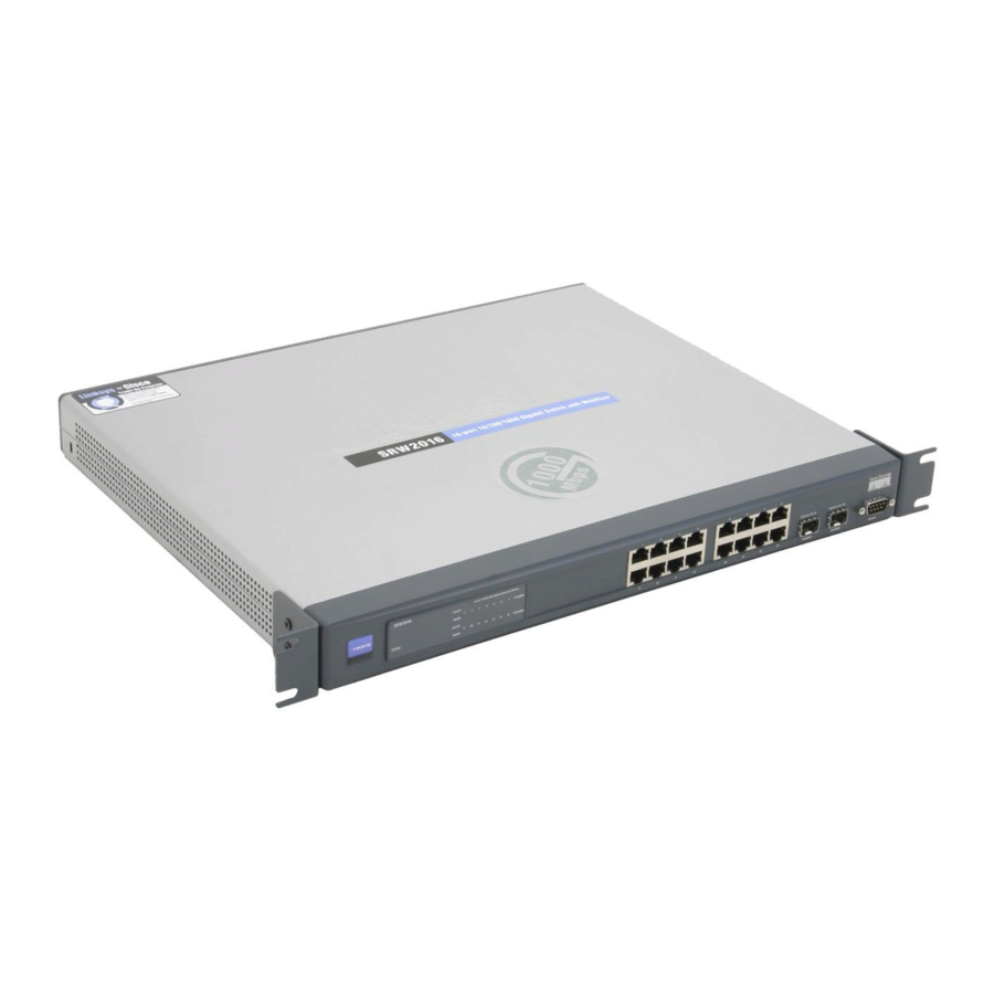
Chapter 2: Getting to Know the Switch Overview The Switches differ in number and types of LEDs and ports. While the 16-Port Gigabit Ethernet Switch is pictured in this chapter, the other Switches are similar in form and function. The Front Panel The Switch's LEDs and ports are located on the front panel. -
Page 14: The Back Panel
Each mini-GBIC port provides a link to a high-speed network segment or individual workstation at speeds of up to 1000Mbps. Use the Linksys MGBT1, MGBSX1, or MGBLH1 mini-GBIC modules with the Switch. The MGBSX1 and the MGBLH1 require fiber cabling with LC connectors, while the MGBT1 requires a Category 5e Ethernet cable with an RJ-45 connector. -
Page 15: Chapter 3: Connecting The Switch
Chapter 3: Connecting the Switch Overview This chapter will explain how to connect network devices to the Switch. For an example of a typical network configuration, see the application diagram shown below. Figure 3-1: Typical Network Configuration for the 16-Port Switch When you connect your network devices, make sure you don’t exceed the maximum cabling distances, which are... -
Page 16: Before You Install The Switch
Placement Options Before connecting cables to the Switch, first you will physically install the Switch. Either set the Switch on its four rubber feet for desktop placement or mount the Switch in a standard-sized, 19-inch wide, 1U high rack for rack- mount placement. -
Page 17: Connecting The Switch
(This PC must be running the VT100 terminal emulation software, such as HyperTerminal.) 7. Connect the supplied power cord to the Switch’s power port, and plug the other end into an electrical outlet. IMPORTANT: Make sure you use the power cord that is supplied with the Switch. Use of a different power cord could damage the Switch. - Page 18 WebView Switches 8. Power on the network devices connected to the Switch. Each active port’s corresponding Link/Act LED will light up on the Switch. If a port has an active Gigabit connection, then its corresponding Gigabit LED will also light up.
-
Page 19: Chapter 4: Using The Console Interface For Configuration
2. On the Connection Description screen, enter a name for this connection. In the example, the name of connection is SRW2016. Select an icon for the application. Then, click the OK button. 3. On the Connect To screen, select a port to communicate with the Switch: COM1, COM2, or TCP/IP. -
Page 20: Connecting To The Switch Through A Telnet Session
Flow control: None Then, click the OK button. Connecting to the Switch through a Telnet Session Open a command line editor and enter telnet 192.168.1.254. Then, press the Enter key. The Login screen will now appear. The first time you open the CLI interface, select Edit and enter admin in the User Name field. -
Page 21: Configuring The Switch Through The Console Interface
Figure 4-6: Switch Main Menu Port Status On the Switch Main Menu screen, select Port Status and press the Enter key if you want to view the status information for the Switch’s ports. The Port Status screen displays the port numbers, their status, Link status, speed and duplex mode, and status of flow control, which is the flow of packet transmissions. -
Page 22: Figure 4-8: Port Configuration
WebView Switches Port Configuration On the Switch Main Menu screen, select Port Configuration and press the Enter key if you want to configure the Switch’s ports. The Port Configuration screen displays the port numbers, their status, auto-negotiation status, speed and duplex mode, and status of flow control, which is the flow of packet transmissions. -
Page 23: Figure 4-10: System Information Menu
WebView Switches System Information Using this screen, you can check the Switch’s firmware versions and general system information. Figure 4-10: System Information Menu Versions The Versions screen displays the Switch’s boot, software, and hardware firmware versions. Figure 4-11: Versions General System Information The General System Information screen displays the Switch’s description, System Up Time, System MAC... -
Page 24: Figure 4-13: Management Settings Menu
Figure 4-13: Management Settings Menu Serial Port Configuration On the Serial Port Configuration screen, the Switch’s baud rate is displayed. Select Edit to make changes. When your changes are complete, press the Esc key to return to the Action menu, and select Save to save your changes. -
Page 25: Figure 4-16: Username & Password Settings
NOTE: The Username & Password Settings screen can also be used to set passwords for other users. Security Settings The Security Settings screen enables you to configure security settings on the Switch, as well as generate and display the certificate. -
Page 26: Figure 4-18: Ssl Certificate Generation
Use the Show Certificate screen to display the internal certificate. Figure 4-19: SSL Certificate IP Configuration The IP Configuration screen displays these choices: the Switch’s IP Address Settings, HTTP, HTTPS Configuration and Network Configuration. Figure 4-20: IP Configuration Chapter 4: Using the Console Interface for Configuration... -
Page 27: Figure 4-21: Ip Address Configuration
Figure 4-21: IP Address Configuration DHCP client. The status of the DHCP client is displayed. If you want the Switch to be a DHCP client, then select ENABLE. If you want to assign an static IP address to the Switch, then enter the IP settings and select DISABLE. -
Page 28: Figure 4-24: Network Configuration
Select Edit to make changes. When your changes are complete, press the Esc key to return to the Action menu, and select Save to save your changes. Figure 4-26: TraceRoute Test Chapter 4: Using the Console Interface for Configuration Configuring the Switch through the Console Interface... -
Page 29: Figure 4-27: File Management
Figure 4-28: Restore System Default Settings Select Reboot System and press the Enter key if you want to restart the Switch. You will be asked if you want to continue. Press the y key to reboot the Switch, or press the n key to cancel. After the Switch has rebooted, the Switch Main Menu screen will appear. -
Page 30: Chapter 5: Using The Web-Based Utility For Configuration
An About button appears at the top of each screen. Clicking this button will bring up the versioning information of the Switch. The LEDs on the screen display status information about their corresponding ports. A green LED indicates a connection, while a blue LED indicates no connection. When you click a port’s LED, the statistics for that port are displayed. -
Page 31: Sys. Info. (System Information) Tab - System Description
Jumbo Frames. If you want to enable this feature on the Switch, select Enabled. You will be notified that this feature will be enabled after the Switch is reset. Otherwise, select Disabled. -
Page 32: Sys. Info. (System Information) Tab - Forwarding Database
WebView Switches Sys. Info. (System Information) Tab - Forwarding Database The Forwarding Database screen lets you define the aging interval of the Switch. Aging Interval (15-630) (secs). This specifies the aging-out period on the Forwarding Database. Click the Submit button to save your changes. -
Page 33: Sys. Info. (System Information) Tab - Time Synchronization
Daylight Saving. Select Daylight Saving to enable it on the Switch. If the Switch should use US daylight savings, then select USA. If the Switch should use EU daylight savings, then select European. If it should use another kind of daylight savings, then select Other and complete the From and To fields. -
Page 34: Ip Conf. (Configuration) Tab - Ip Addr. (Address)
WebView Switches IP Conf. (Configuration) Tab - IP Addr. (Address) The IP Address screen allows you to assign DHCP or static IP settings to interfaces and assign default gateways. DHCP Interface. If you are using the DHCP Interface, then select the radio button and specify the VLAN on which the DHCP IP address is configured. -
Page 35: Switch Conf. (Configuration) Tab - Interface Conf. (Configuration)
Switch Conf. (Configuration) Tab - Interface Conf. (Configuration) The Interface Configuration screen shows you the settings for each of the Switch’s ports. Where many ports are present, you can scroll to the right on the screen to view the settings for further ports. -
Page 36: Figure 5-9: Interface Configuration - Change Settings
Modify the settings of Selected Port button. On the new screen that appears, you can change the port’s settings. (Some settings shown may not be available, depending on the type of switch you have and other settings you have configured for that port.) Interface. - Page 37 MDI/MDIX. Select the Auto setting if you want the port to automatically detect the cable type. Select MDI if the port is connected to an end station. Select MDIX if the port is connected to a hub or another switch.
-
Page 38: Switch Conf. (Configuration) Tab - Vlan
ID as well as the VLAN name. Chose the port, as well as the Member and Tagging type. Then, click the Submit button. Chapter 5: Using the Web-based Utility for Configuration Switch Conf. (Configuration) Tab - VLAN Figure 5-10: Switch Configuration - VLAN Figure 5-11: Switch Configuration - Create VLAN... -
Page 39: Switch Conf. (Configuration) Tab - Vlan Interface Settings
WebView Switches Switch Conf. (Configuration) Tab - VLAN Interface Settings The VLAN Interface Settings screen lets you define properties of the interfaces that are associated with VLANs. Interface. This is the physical address of the interface, Port or LAG. Interface VLAN Mode. One of the following VLAN modes will appear •... -
Page 40: Switch Conf. (Configuration) Tab - Gvrp Parameters
WebView Switches Switch Conf. (Configuration) Tab - GVRP Parameters The name of this section is different depending on the type of Switch you are using. Gigabit Ethernet Switches show the GVRP Parameters screen. Fast Ethernet Switches show the PVE Mapping screen... -
Page 41: Switch Conf. (Configuration) Tab - Lag Conf. (Configuration)
To modify a LAG, click the LAG’s Edit icon, which resembles a pencil. On the new screen that appears, you can modify the LAG for each of the Switch’s ports. Where many ports are present, you can scroll to the right on the screen to view the settings for further ports. -
Page 42: Switch Conf. (Configuration) Tab - Port Mirroring
Switch Conf. (Configuration) Tab - Port Mirroring The Port Mirroring screen lets you configure the Switch’s port mirroring settings. Port mirroring can be used for diagnostics or debugging. It forwards copies of incoming and outgoing packets from one port to a monitoring port. -
Page 43: Switch Conf. (Configuration) Tab - Lacp
WebView Switches Switch Conf. (Configuration) Tab - LACP The LACP screen allows you to enable the use of the Link Aggregation Control Protocol (LACP) on relevant links for LAGs. Listed on this screen are the LACP LAGs. LACP System Priority (1 - 65535). Select the LACP priority value for the system. Then, click the Submit button. -
Page 44: Switch Conf. (Configuration) Tab - Igmp Snooping
IGMP Snooping Status. Indicates if IGMP snooping is enabled or disabled on the VLAN. Enable Auto Learn. Indicates if Auto Learn is enabled or disabled on the Switch. If Auto Learn is enabled, the Switch automatically learns where other Multicast groups are located. -
Page 45: Switch Conf. (Configuration) Tab - Bridge Multicast
Multicast service groups. From this screen, you can view the VLAN ID for each of the Switch’s ports. Where many ports are present, you can scroll to the right on the screen to view the settings for further ports. -
Page 46: Switch Conf. (Configuration) Tab - Bridge Multicast Forward All
Switch Conf. (Configuration) Tab - Bridge Multicast Forward All The Bridge Multicast Forward All screen contains fields for attaching ports or LAGs to a switch that is attached to a neighboring Multicast router/switch. Once IGMP Snooping is enabled, Multicast packets are forwarded to the appropriate port or VLAN. -
Page 47: Qos Tab - Cos Settings
Weighted Round Robin (WRR), for which no single application dominates the forwarding capacity. The CoS Settings screen lets you enable or disable CoS for various ports. CoS Mode. This indicates whether CoS is enabled or disabled for the Switch. Interface. This indicates the interface to be configured. -
Page 48: Qos Tab - Queue Settings
WebView Switches QoS Tab - Queue Settings The Queue Settings screen lets you select the CoS method and assign bandwidth values for your queues. Queue. This is the queue number. Scheduling Strict Priority. If you want traffic scheduling to be based on queue priority, then click this radio button. WRR. -
Page 49: Qos Tab - Bandwidth
WebView Switches QoS Tab - Bandwidth Use the Bandwidth Settings page to define the bandwidth settings for specified ingress and egress interface. Modifying queue scheduling affects the queue settings globally. Port. Shows the port to which bandwidth settings are applied. Ingress Rate Limit. -
Page 50: Security Tab - Local Users/System Password
WebView Switches Security Tab - Local Users/System Password This screen will appear as Local Users for those using a Gigabit Ethernet Switch and as System Password for those using a Fast Ethernet Switch. This screen allows you to change the password for the Switch. To modify a user’s Password information, click Figure 5-31: Security - Local Users/System Password the Edit icon next to the user’s name to open the edit screen. -
Page 51: Security Tab - 802.1X Port Conf. (Configuration)
Supplicant Timeout (sec). This is the number of seconds that the Switch waits before EAP requests are resent to the client. Server Timeout (sec). This is the number of seconds that the Switch waits before it resends a request to the RADIUS server. -
Page 52: Figure 5-35: 802.1X Port Configuration - Change Settings
Supplicant Timeout. Enter the number of seconds that the Switch waits before EAP requests are resent to the client. Server Timeout. Enter the number of seconds that the Switch waits before it resends a request to the RADIUS server. Click the Submit button to save your changes. -
Page 53: Security Tab - Radius Server
Number of Retries. This is the number of requests sent to the RADIUS server before a failure occurs. Timeout for Reply. This is the number of seconds the Switch waits for an answer from the RADIUS server before retrying the query or switching to the next server. - Page 54 Default Retries (1-10). Enter the number of retries allowed before a failure occurs. To use the default, click the Use Default checkbox. Default Timeout for Reply (1-30). Enter the default number of seconds the Switch waits for an answer from the RADIUS server before retrying the query or switching to the next server.
-
Page 55: Security Tab - Storm Control
Port. Indicates the port on which storm control is enabled. Enable Broadcast Control. Enables broadcast control on the port. Broadcast Mode. Specifies the broadcast mode currently enabled on the Switch. These can be: • Unknown Unicast, Multicast & Broadcast • Multicast & Broadcast •... -
Page 56: Security Tab For Srw2048 Switches - Acl
WebView Switches Security Tab for SRW2048 Switches - ACL The ACL screen lists the access profiles and allows you to configure access profiles for the Switch. Access Profile. This is the name of the access profile. Activated. You can activate an access profile by selecting the radio button. You can deactivate an access profile by deselecting the radio button. -
Page 57: Security Tab For Srw2048 Switches - Profile Rules
Security Tab for SRW2048 Switches - Profile Rules The Profile Rules screen contains fields for defining profiles and rules for accessing the Switch. Access to management functions can be limited to user groups, which are defined by ingress interfaces and source IP address or source IP subnets. -
Page 58: Figure 5-43: Srw2048 Switch Security - Authentication Profiles
Methods. User authentication methods. The possible options are: • None — No user authentication occurs. • Local — User authentication occurs at the Switch level. The Switch checks the user name and password for authentication. • RADIUS — User authentication occurs at the RADIUS server. -
Page 59: Figure 5-44: Srw2048 Switch Security - Authentication Mapping
• TACACS+ - Authentication occurs at the TACACS+ server. Chapter 5: Using the Web-based Utility for Configuration Security Tab for SRW2048 Switches - Profile Rules NOTE: This section applies to the SRW2048 Switch ONLY. For all other switches, refer to the sections titled Security Tab for Other Switches. -
Page 60: Figure 5-45: Srw2048 Switch Security - Tacacs
Status. The connection status between the device and the TACACS+ server., either Connected or Not Connected. Chapter 5: Using the Web-based Utility for Configuration Security Tab for SRW2048 Switches - Profile Rules NOTE: This section applies to the SRW2048 Switch ONLY. For all other switches, refer to the sections titled Security Tab for Other Switches. -
Page 61: Security Tab For Other Switches - Acl
WebView Switches Security Tab for Other Switches - ACL The ACL screen lists the access profiles and allows you to configure access profiles for the Switch. Access Profile. This is the name of the access profile. Activated. You can activate an access profile by selecting the radio button. You can deactivate an access profile by deselecting the radio button. -
Page 62: Security Tab For Other Switches - Mac Based Acl
Security Tab for Other Switches - MAC Based ACL NOTE: This section does not apply to the SRW2048 Switch. If you have a SRW2048 Switch, refer to the sections titled Security Tab for SRW2048 Switches. Figure 5-48: Fast Ethernet Security - MAC Based ACL... -
Page 63: Security Tab For Other Switches - Acl Mapping
Security Tab for Other Switches - ACL Mapping NOTE: This section does not apply to the SRW2048 Switch. If you have a SRW2048 Switch, refer to the sections titled Security Tab for SRW2048 Switches. Figure 5-49: Fast Ethernet Security - ACL Mapping... -
Page 64: Sntp Tab - Global Settings
The Global Settings screen lets you set the Simple Network Time Protocol (SNTP) settings. SNTP makes possible accurate time synchronization by a network SNTP server for network devices. Using SNTP, the Switch is synchronized with the rest of the network and set with the correct time. -
Page 65: Sntp Tab - Authentication
Click the Submit button to save your change. Figure 5-51: SNTP - Authentication Encryption Key ID. Displayed here is the encryption key used to authenticate the SNTP server and Switch. Authentication Key. This is the key used for authentication. Trusted Key. This indicates if there is an encryption key used (unicast/anycast) or elected (broadcast) to authenticate the SNTP server. -
Page 66: Sntp Tab - Servers
Offset. This is the difference between the Switch’s time zone and the server’s time zone. Delay. This shows how long it takes for data from the server to travel to the Switch. Add icon. To add an SNTP server, click the paper and pencil icon. Configure its settings on the screen that appears, as described below. -
Page 67: Sntp Tab - Interface Settings
SNTP Server. Enter the IP address of an SNTP server. You can have up to eight SNTP servers. Poll Interval. Enable this feature if you want the Switch to poll the SNTP server for system time information. Encryption Key ID. Select the encryption key used to communicate between the SNTP server and Switch. -
Page 68: Statistics Tab - Interface Statistics
WebView Switches Statistics Tab - Interface Statistics The Interface Statistics screen displays statistics for received and transmitted packets. Interface. Select the appropriate interface, Port or LAG. Then, select the appropriate number from the drop- down menu. Refresh Rate. Select how often you want the interface statistics refreshed. Receive Statistics Total Bytes. -
Page 69: Statistics Tab - Etherlike Statistics
WebView Switches Statistics Tab - Etherlike Statistics The Etherlike Statistics screen displays interface statistics. Interface. Select the appropriate interface, Port or LAG. Then, select the appropriate number from the drop- down menu. Refresh Rate. Select how often you want the interface statistics refreshed. Frame Check Sequence (FCS) Errors. -
Page 70: Statistics Tab - Rmon Statistics
Refresh Rate. Select how often you want the interface statistics refreshed. Drop Events. This is the number of dropped events that have occurred on the interface since the Switch was last refreshed. Received Bytes (Octets). This is the number of octets received on the interface since the Switch was last refreshed. - Page 71 WebView Switches Frames of 64 Bytes. This is the number of 64-byte frames received on the interface since the Switch was last refreshed. Frames of 65 to 127 Bytes. This is the number of 65- to 127-byte frames received on the interface since the Switch was last refreshed.
-
Page 72: Statistics Tab - Rmon History Control
WebView Switches Statistics Tab - RMON History Control The RMON History Control screen contains information about samples of data taken from ports. History Entry No. This is the entry number for a RMON History entry. Source Interface. This is the interface from which the history samples were taken, either a port or LAG. Sampling Interval. -
Page 73: Statistics Tab - Rmon History Log
Multicast Packets. This is the number of good multicast packets received on the interface since the Switch was last refreshed. CRC Align Errors. This is the number of CRC and Align errors that occurred on the interface since the Switch was last refreshed. -
Page 74: Statistics Tab - Rmon Alarms
WebView Switches Statistics Tab - RMON Alarms The RMON Alarms screen displays the network alarms you have set. When the network experiences problems or events, such as rising and falling thresholds, then a network alarm will occur. Alarm Entry. This identifies a specific alarm. Figure 5-59: Statistics - RMON Alarms Counter Name. -
Page 75: Figure 5-60: Statistics - Add Rmon Alarm Entry
WebView Switches To add an entry, click the paper and pencil icon. On the new screen that appears, you can configure the following settings: Alarm Entry. This is the number of the alarm entry. Interface. Select the interface for which RMON statistics are displayed, either a port or LAG. Then, select the appropriate number from the drop-down menu. -
Page 76: Statistics Tab - Rmon Events Control
WebView Switches Statistics Tab - RMON Events Control The RMON Events Control screen shows the RMON events you have configured. Event Entry. This identifies the event. Community. This is the community to which the event belongs. Figure 5-61: Statistics - RMON Events Control Description. -
Page 77: Statistics Tab - Rmon Events Log
WebView Switches Statistics Tab - RMON Events Log The RMON Events Log screen displays a list of RMON events. Event. This is the number of the RMON Event Log entry. Log No. This is the log number. Log Time. This is the time when the log entry was entered. Figure 5-62: Statistics - RMON Events Log Description. -
Page 78: Statistics Tab - Eap Statistics
WebView Switches Statistics Tab - EAP Statistics The EAP Statistics screen displays information about EAP packets received on a specific port. Port. Select the port you want to poll for statistics. Refresh Rate. Select how often you want the EAP statistics to be refreshed. Frames Receive. -
Page 79: Statistics Tab - Gvrp Statistics
WebView Switches Statistics Tab - GVRP Statistics The GVRP Statistics screen displays information about GVRP packets received on a specific port. Interface. Specifies whether statistics are displayed for a port or LAG. Refresh Rate. Amount of time that passes before the interface statistics are refreshed. GVRP Statistics Table Attribute (Counter). -
Page 80: Logs Tab - Message Log
WebView Switches Logs Tab - Message Log The Message Log screen shows information about log entries saved to the Log file in flash memory. Log entries are listed in a descending column, numbered on the left. Log Index. This is the log number. Log Time. -
Page 81: Logs Tab - Global Parameters
The Global Parameters screen lets you define which events are recorded by which logs. You can enable logs for the Switch and define specific logs. Logging. If you want the Switch to keep logs, select Enable. Otherwise, select Disable. Attribute. Displayed here is Max RAM Log Entries (20-400). This stands for the maximum number of log entries held in RAM. -
Page 82: Snmp Tab
SNMP v3 supports the following features: • Security • Feature Access Control Chapter 5: Using the Web-based Utility for Configuration SNMP Tab NOTE: SNMP v3 is not supported on the SRW2016 or SRW2024 Switches and will not appear in the utilities for these products. -
Page 83: Figure 5-68: Snmp - Global Parameters
WebView Switches • Traps The switches generate the following traps: • Copy trap • Stacking traps This section contains the following topics: • Configuring SNMP Security • Configuring SNMP SecurityConfiguring SNMP Notifications Configuring SNMP Security Defining SNMP Security The SNMP Global Parameters screen permits enabling both SNMP and Authentication notifications. •... -
Page 84: Figure 5-69: Snmp - Views
WebView Switches Defining SNMP Views SNMP Views provide access or block access to device features or feature aspects. For example, a view can be defined which states that SNMP group A has Read Only (R/O) access to Multicast groups, while SNMP group B has Read-Write (R/W) access to Multicast groups. -
Page 85: Figure 5-70: Snmp - Group Profile
WebView Switches Defining SNMP Group Profiles The Group Profiles screen provides information for creating SNMP groups, and assigning SNMP access control privileges to SNMP groups. Groups allow network managers to assign access rights to specific device features, or features aspects. The Group Profiles screen contains the following fields: •... -
Page 86: Figure 5-71: Snmp - Add Group Profile
WebView Switches To add an entry, click the paper and pencil icon. On the new screen that appears, you can configure the following settings: • Group Name. Enter a name for the user-defined group to which access control rules are applied. The field range is up to 30 characters. -
Page 87: Figure 5-72: Snmp - Group Membership
WebView Switches Defining SNMP Group Members The Group Membership screen enables assigning system users to SNMP groups, as well as defining the user authentication method. The Group Membership screen contains the following fields: • User Name. Contains a list of user-defined user names. The field range is up to 30 alphanumeric characters. •... -
Page 88: Figure 5-73: Snmp - Add Group Membership
WebView Switches To add an member, click the paper and pencil icon. On the new screen that appears, you can configure all of the fields from the Group Membership screen, along with the following: • Authentication Key. Defines the HMAC-MD5-96 or HMAC-SHA-96 authentication level. The authentication and privacy keys are entered to define the authentication key. -
Page 89: Figure 5-75: Snmp - Properties
The SNMP Notification Properties screen contains parameters for defining SNMP notification parameters. Enable SNMP Notifications. Check this box to enable the Switch to send SNMP notifications. Enable Authentication Notifications. Check this box to enable the Switch to send SNMP Authentication failure notifications. -
Page 90: Figure 5-76: Snmp - Notification Filter
WebView Switches Defining SNMP Notification Filters The SNMP Notification Filter screen permits filtering traps based on OIDs. Each OID is linked to a device feature or a feature aspect. The SNMP Notification Filter Page also allows network managers to filter notifications. The SNMP Notification Filter screen contains the following fields: •... -
Page 91: Figure 5-77: Snmp - Notification Receiver
Retries (1-255). This displays the amount of times the Switch resends an inform request. The default settings is To add a recipient, click the paper and pencil icon. Configure all the fields on the screen that appears and click the Submit button. -
Page 92: Maintenance Tab - Telnet
The Reset screen lets you reset the Switch from a remote location. Reset the Device. If you want to reset the Switch, click Reset the Device. You will be asked to confirm the reset. Click the OK button. After the Switch is reset, you will be prompted for a user name and password before you can access the Web-based Utility. -
Page 93: Maintenance Tab - File Upload
Configuration file holds all startup file commands and commands entered during the current session. The Startup Configuration file holds the startup file commands needed by the Switch to power on or be rebooted. Click the Submit button to begin the download of the firmware or configuration file. -
Page 94: Maintenance Tab - Restore Defaults
Configuration file holds all startup file commands and commands entered during the current session. The Startup Configuration file holds the startup file commands needed by the Switch to power on or be rebooted. Click the Submit button to begin the upload of the firmware or configuration file. -
Page 95: Maintenance Tab - Http File Download
Maintenance Tab - HTTP File Download The HTTP File Download screen allows you to download a file to the Switch via HTTP. Source File Name. Enter the file path of the file you want to download, or click the Browse button to browse for the source file. -
Page 96: Spanning Tree Tab - Global Settings
The Global Settings screen contains the following fields: Spanning Tree State. Enables or disables STP, Rapid STP, or MSTP on the Switch. STP Operation Mode. Available on the Gigabit Ethernet Switches ONLY. Indicates the STP mode by which STP is enabled on a Gigabit Ethernet Switch. - Page 97 WebView Switches Path Cost Default Values. Specifies the method used to assign default path costs to STP ports. The possible field values are: Short - Specifies 1 through 65,535 range for port path costs. This is the default value. Long - Specifies 1 through 200,000,000 range for port path costs. The default path costs assigned to an interface vary according to the selected method.
-
Page 98: Spanning Tree Tab - Stp Interface Settings
Root-Provides the lowest cost path to forward packets to root switch. Designated-Indicates that the port via which the designated switch is attached to the LAN. Alternate-Provides an alternate path to the root switch from the root interface. Chapter 5: Using the Web-based Utility for Configuration... - Page 99 WebView Switches Backup-Provides a backup path to the designated port path toward the Spanning Tree leaves. Backup ports occur only when two ports are connected in a loop by a point-to-point link. Backup ports also occur when a LAN has two or more connections connected to a shared segment. Disabled-Indicates the port is not participating in the Spanning Tree.
-
Page 100: Spanning Tree Tab On Srw2048 Switches - Rstp Interface Settings
Root-Provides the lowest cost path to forward packets to root switch. Designated-Indicates that the port or LAG via which the designated switch is attached to the LAN. Alternate-Provides an alternate path to the root switch from the root interface. - Page 101 The link remains configured for communications until explicit LCP or NCP packets close the link, or until some external event occurs. This is the actual switch port link type. It may differ from the administrative state. Point-to-Point Operational Status. The Point-to-Point operating state.
-
Page 102: Spanning Tree Tab On Srw2048 Switches - Mstp Properties
WebView Switches Spanning Tree Tab on SRW2048 Switches - MSTP Properties MSTP operation maps VLANs into STP instances. Multiple Spanning Tree provides differing load balancing scenario. For example, while port A is blocked in one STP instance, the same port is placed in the Forwarding State in another STP instance. -
Page 103: Spanning Tree Tab On Srw2048 Switches - Mstp Instance Settings
WebView Switches Spanning Tree Tab on SRW2048 Switches - MSTP Instance Settings Use this screen to configure MSTP instances. Instance ID. Defines the MSTP instance. The field range is 1-15. Included VLANs. Displays VLANs mapped to the selected instance. Each VLAN belongs to one instance. Bridge Priority. -
Page 104: Spanning Tree Tab On Srw2048 Switches - Mstp Interface Settings
WebView Switches Spanning Tree Tab on SRW2048 Switches - MSTP Interface Settings The MSTP Interface Settings screen contains parameters assigning MSTP settings to specific interfaces. Instance ID. Lists the MSTP instances configured on the device. Possible field range is 1-15. Interface. -
Page 105: Help Tab
WebView Switches Designated Bridge ID. The bridge ID number that connects the link or shared LAN to the root. Designated Port ID. The Port ID number on the designated bridge that connects the link or the shared LAN to the root. -
Page 106: Appendix A: About Gigabit Ethernet And Fiber Optic Cabling
A fiber connection always require two fiber cables: one transmits data, and the other receives it. Each fiber optic cable is tipped with a connector that fits into a fiber port on a network adapter, hub, or switch. In the USA, most cables use a square SC connector that slides and locks into place when plugged into a port or connected to another cable. -
Page 107: Appendix B: Windows Help
WebView Switches Appendix B: Windows Help Almost all networking products require Microsoft Windows. Windows is the most used operating system in the world and comes with many features that help make networking easier. These features can be accessed through Windows Help and are described in this appendix. TCP/IP Before a computer can communicate within a network, TCP/IP must be enabled. -
Page 108: Appendix C: Glossary
WebView Switches Appendix C: Glossary Adapter - A device that adds network functionality to your PC. AES (Advanced Encryption Standard) - A security method that uses symmetric 128-bit block data encryption. Backbone - The part of a network that connects most of the systems and networks together, and handles the most data. - Page 109 WebView Switches DDNS (Dynamic Domain Name System) - Allows the hosting of a website, FTP server, or e-mail server with a fixed domain name (e.g., www.xyz.com) and a dynamic IP address. Default Gateway - A device that forwards Internet traffic from your local area network. DHCP (Dynamic Host Configuration Protocol) - A networking protocol that allows administrators to assign temporary IP addresses to network computers by “leasing”...
- Page 110 WebView Switches Full Duplex - The ability of a networking device to receive and transmit data simultaneously. Gateway - A device that interconnects networks with different, incompatible communications protocols. Half Duplex - Data transmission that can occur in two directions over a single line, but only one direction at a time.
- Page 111 WebView Switches Node - A network junction or connection point, typically a computer or work station. Packet - A unit of data sent over a network. Ping (Packet INternet Groper) - An Internet utility used to determine whether a particular IP address is online. POP3 (Post Office Protocol 3) - A standard mail server commonly used on the Internet.
- Page 112 WebView Switches Switch - 1. A data switch that connects computing devices to host computers, allowing a large number of devices to share a limited number of ports. 2. A device for making, breaking, or changing the connections in an electrical circuit.
-
Page 113: Appendix D: Specifications
802.3z Gigabit Ethernet, 802.3x Flow Control Ports SRW2016 - 16 10/100/1000 RJ-45 ports and 2 shared MiniGBIC slots SRW2024 - 24 10/100/1000 RJ-45 ports and 2 shared MiniGBIC slots SRW2048 - 48 10/100/1000 RJ-45 ports and 2 shared MiniGBIC slots... - Page 114 SRW248G4 : 16.93” x 1.75” x 13.78” (430 mm x 44.45 mm x 350 mm) SRW224G4 : 16.93” x 1.75” x 7.97” (430 mm x 44.45 mm x 202.5 mm) Unit Weight SRW2016 - 7.30 lbs. (3.31 kg) SRW2024 - 7.35 lbs. (3.33 kg) SRW2048 : 8.60 lbs. (3.9 kg) SRW248G4 : 8.60 lbs.
-
Page 115: Appendix E: Warranty Information
Your exclusive remedy and Linksys' entire liability under this warranty will be for Linksys at its option to repair or replace the Product or refund Your purchase price less any rebates. -
Page 116: Appendix F: Regulatory Information
WebView Switches Appendix F: Regulatory Information FCC STATEMENT This product has been tested and complies with the specifications for a Class B digital device, pursuant to Part 15 of the FCC Rules. These limits are designed to provide reasonable protection against harmful interference in a residential installation. -
Page 117: Appendix G: Contact Information
Niemals ein Übertragungslaser betrachten, während dieses eingeschaltet ist. Niemals direkt auf den Faser-TX-Anschluß und auf die Faserkabelenden schauen, während diese eingeschaltet sind. Please read the following safety information carefully before installing the switch: WARNING: Installation and removal of the unit must be carried out by qualified personnel only. - Page 118 The mains cord must be <HAR> or <BASEC> marked and be of type HO3VVF3GO.75 (minimum). IEC-320 receptacle. Veuillez lire à fond l'information de la sécurité suivante avant d'installer le Switch: AVERTISSEMENT: L’installation et la dépose de ce groupe doivent être confiés à un personnel qualifié.
- Page 119 WebView Switches La prise secteur doit se trouver à proximité de l’appareil et son accès doit être facile. Vous ne pouvez mettre l’appareil hors circuit qu’en débranchant son cordon électrique au niveau de cette prise. L’appareil fonctionne à une tension extrêmement basse de sécurité qui est conforme à la norme IEC 60950. Ces conditions ne sont maintenues que si l’équipement auquel il est raccordé...
- Page 120 Warning: This switch uses lasers to transmit signals over fiber optic cable. The lasers are compliant with the requirements of a Class 1 Laser Product and are inherently eye safe in normal operation. However, you should never look directly at a transmit port when it is powered on.
- Page 121 All printed documentation for this product uses biodegradable paper that originates from sustained and managed forests. The inks used in the printing process are non-toxic. Purpose This guide details the hardware features of the switch, including Its physical and performance-related characteristics, and how to install the switch. Audience...
- Page 122 This guide is for system administrators with a working knowledge of network management. You should be familiar with switching and networking concepts. Zielgruppe Dieser Anleitung ist fuer Systemadministratoren mit Erfahrung im Netzwerkmangement. Sie sollten mit Switch- und Netzwerkkonzepten vertraut sein. Appendix F: Regulatory Information...
- Page 123 Can't find information about a product you want to buy on the web? Do you want to know more about networking with Linksys products? Give our advice line a call at: Or fax your request in to: If you experience problems with any Linksys product,...