Table of Contents
Advertisement
Quick Links
Advertisement
Chapters
Table of Contents

Related Manuals for Endress+Hauser analytikjena multi N/C pharma HT


Summary of Contents for Endress+Hauser analytikjena multi N/C pharma HT
- Page 1 Operating Manual multi N/C pharma HT TOC/TNb Analyzer...
- Page 2 Manufacturer Analytik Jena GmbH Konrad-Zuse-Strasse 1 07745 Jena / Germany Phone: +49 3641 77 70 Fax: +49 3641 77 9279 Email: info@analytik-jena.com Technical Service Analytik Jena GmbH Konrad-Zuse-Strasse 1 07745 Jena / Germany Phone: +49 3641 77 7407 Fax: +49 3641 77 9279 Email: service@analytik-jena.com For a proper and safe use of this product follow the instructions.
-
Page 3: Table Of Contents
multi N/C pharma HT Table of contents Table of contents 1 Basic information................................About this user manual ............................ Analyzer area of application ..........................Intended use ..............................2 Security .................................... Safety labeling on the device ........................... Requirements for the operating personnel..................... 10 Safety instructions, transport and commissioning .................. - Page 4 Table of contents multi N/C pharma HT System suitability test............................34 4 Installation and commissioning ............................. 36 Installation conditions ............................36 4.1.1 Ambient conditions ............................36 4.1.2 Device layout and space requirements ......................36 4.1.3 Power supply..............................37 4.1.4 Gas supply ................................. 37 Unpacking and setting up the device.......................
- Page 5 multi N/C pharma HT Table of contents Cleaning the TIC condensate vessel......................... 96 6.10 Condensation coil maintenance........................97 6.11 Replacing the water traps ..........................98 6.12 Replacing the halogen trap..........................101 6.13 Removing the integrated solids module ......................103 6.14 Maintaining the chemiluminescence detector (CLD) ..................104 7 Troubleshooting................................
- Page 6 Table of contents multi N/C pharma HT...
-
Page 7: Basic Information
multi N/C pharma HT Basic information Basic information About this user manual Content The operating manual describes the following device model(s): ¡ multi N/C pharma HT The device is intended to be operated by qualified specialist personnel under observance of the operating manual. The operating manual provides information about the design and operation of the de- vice and provides operating personnel with the necessary know-how for safe handling of the device and its components. -
Page 8: Intended Use
Basic information multi N/C pharma HT The analyzer can optionally be equipped with an integrated solids module (Swab Test module). This permits carbon detection in solids in the lower concentration range, e.g., during cleaning verification (swab test). The control and analysis software provides complete data integrity and conforms to the pharmaceutical guidelines in 21 CFR Part 11 and EudraLex Volume 4 Annex 11. -
Page 9: Security
multi N/C pharma HT Security Security For your own safety and to ensure error-free and safe operation of the device, please read this chapter carefully before commissioning. Observe all safety instructions listed in this user manual and all messages and infor- mation displayed on the monitor by the control and analysis software. -
Page 10: Requirements For The Operating Personnel
Security multi N/C pharma HT Mandatory action Meaning Comment labels/information symbols Observe the operating On the side parts and the rear of the manual device: Before starting work, read the user manual. For People' s Republic of The device contains controlled sub- China only stances. -
Page 11: Safety Instructions: During Operation
multi N/C pharma HT Security Safety instructions: during operation 2.4.1 Summary of safety instructions The operator must make sure that the device and its safety equipment is in sound condition each time before starting up the device. This applies in particular after each modification or extension of the device or its repair. -
Page 12: Electrical System Safety Instructions
Security multi N/C pharma HT 2.4.3 Electrical system safety instructions Life-threatening electrical voltages occur in the device in the area of the right side component! Contact with live components may cause death, serious injury or painful electrical shock. ¡ The power plug must be connected to a proper power outlet to ensure that the device meets protection class I (ground connector). -
Page 13: Safety Instructions - Maintenance And Repair
multi N/C pharma HT Security Special care must be taken when handling concentrated acids. The regulations ¡ and notes in the safety data sheets for the handling of orthophosphoric acid ) or hydrochloric acid (HCl) must be observed. ¡ The catalyst supplied by the manufacturer should be handled with the usual cau- tion when handling chemicals. -
Page 14: Behavior During Emergencies
Security multi N/C pharma HT See also 2 Maintenance and care [} 77] Behavior during emergencies If there is no immediate risk of injury, switch off the device and the connected ¡ system components immediately in hazardous situations or in the event of an accident and/or disconnect the power plugs from the power outlets. -
Page 15: Function And Design
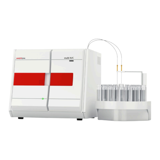
multi N/C pharma HT Function and design Function and design Layout The analyzer is a compact table-top device with permanently installed main compo- nents. Further accessories and reagents are required for the measurement process. Control of the analyzer and analysis of the measurement data is performed via the mul- tiWin software. -
Page 16: Sample Supply System
Function and design multi N/C pharma HT Figure 2 Analyzer, left side wall opened 1 Gas box 2 Combustion system 3 Condensation coil 3.1.1 Sample supply system Sample supply is carried out as flow injection via syringe pump with 2-port valve. The in- jection volume is 50 to 3000 µl. -
Page 17: Hose System
multi N/C pharma HT Function and design 3.1.2 Hose system Hose diagram The connection between the individual components is made with labeled hoses. The numbers and letters circled in the hose diagram correspond to the labels on the hoses in the analyzer. -
Page 18: Figure 5 Setting The Npoc Purge Flow
Function and design multi N/C pharma HT Figure 5 Setting the NPOC purge flow Condensate pump The condensate pump pumps the condensate or the waste solution from TIC determina- tion out automatically after each measurement. The condensate pump is located behind the front doors next to the halogen trap. -
Page 19: Combustion System
multi N/C pharma HT Function and design Connection method Inside the device, most gas connections have been implemented via FAST connectors (FAST – Fast, Safe, Tight). These connectors provide a tight transition between the hoses and connections with different diameters. The soft sleeves prevent the risk of glass breakage in comparison to rigid screw connections. -
Page 20: Measuring Gas Drying And Cleaning
Function and design multi N/C pharma HT Figure 10Combustion furnace 3.1.4 Measuring gas drying and cleaning Condensation coil The glass condensation coil is located to the right of the furnace and is attached to the outlet of the combustion tube. The condensation coil quickly cools the measuring gas. The water vapor contained in the measuring gas condenses. -
Page 21: Figure 12 Tic Condensation Module
multi N/C pharma HT Function and design The top middle connection on the glass container is connected to the phosphoric acid pump. The phosphoric acid pump pumps phosphoric acid (10 %) into the TIC reactor for each TIC determination. The cooling block dries the measuring gas by freezing out the water vapor. The dry mea- suring gas is routed via the top connection out of the TIC condensate container. -
Page 22: Figure 13 Water Traps
Function and design multi N/C pharma HT Figure 13Water traps 1 Disposable retention filter 2 TC prefilter Halogen trap The halogen trap removes interfering components (halogens, halogen-hydrogen com- pounds) from the measuring gas. It also protects the detectors and the flowmeter in this manner. -
Page 23: Detection
multi N/C pharma HT Function and design 3.1.5 Detection NDIR detector The NDIR detector (non-dispersive infrared absorption detector) is behind the right side wall of the analyzer. Gases with molecules from different atoms have specific absorption bands in the in- frared wavelength range. -
Page 24: Indicator And Control Elements, Connections
Function and design multi N/C pharma HT 3.1.6 Indicator and control elements, connections LED display A green LED is installed on the left door of the analyzer. The LED is lit when the analyzer is switched on, indicating operational readiness. Figure 15Status LED The LED strip behind the right door indicates different operating states of the analyzer. -
Page 25: Accessories
multi N/C pharma HT Function and design Figure 17Device rear 1 "Power switch" main switch 2 "FUSE" mains fuse holder 3 "Main plug" mains connection 4 "CLD" gas connection 5 "O /Air" carrier gas connection 6 Connection of the neutral conductor on the autosampler 7 "waste"... -
Page 26: Additional Options For The Analyzer
Function and design multi N/C pharma HT Additional options for the analyzer Autosampler The following autosamplers are available for the analyzer: AS vario with various tray sizes ¡ AS 10e for 10 samples ¡ AS 21hp for 21 samples ¡ ¡... -
Page 27: Measuring Methods
multi N/C pharma HT Function and design The sample aliquot is dosed directly into the hot zone of the filled reactor (combustion tube). Here, the pyrolysis and oxidation of the sample in the carrier gas flow is per- formed with the aid of the catalyst. The carrier gas is also used as an oxidizing agent. R + O →... -
Page 28: Tic Analysis
Function and design multi N/C pharma HT TOC analysis can be used when the sample contains easily purgeable organic substances such as benzol, cyclohexane, chloroform, etc. If the TIC content of the sample is signifi- cantly above the TOC content, TOC analysis should not be applied. detection is possible in parallel to TOC detection. -
Page 29: Tn Analysis
multi N/C pharma HT Function and design The sample is filtered outside of the analyzer and then analyzed as a TOC sample. 3.4.6 analysis : Total Nitrogen bound The content of nitrogen compounds in aqueous samples can be determined in the ana- lyzer. -
Page 30: Daily Factor
Function and design multi N/C pharma HT Take the blank value of the preparation water into account for measurements in the range of low concentration (<10 mg/l). Single point calibration For low TOC concentrations such as those in the pharmaceutical industry, single point calibration is a very good solution. -
Page 31: Method Characteristics
multi N/C pharma HT Function and design TC/NPOC The TC channel is calibrated directly for the TC parameter, and after sample purging for the NPOC parameter. The concentration c is proportional to integral I = f(I The TIC channel is calibrated. The following applies: c = f(I The calculated parameters appear in the method in the TIC analysis channel. -
Page 32: Other Calculations
Function and design multi N/C pharma HT Method variation coefficient The variation coefficient of the method (relative standard deviation of the method) is used for the comparison of different calibrations with different calibration ranges. Correlation coefficient The correlation coefficient compares the dispersion of the calibration measuring points of the regression function with the total dispersion of the calibration. -
Page 33: Blank Values
multi N/C pharma HT Function and design Blank values 3.7.1 Water blank values Preparation water blank value Especially for measurements with low TOC concentrations (µg/l range), the TOC content of the water used to prepare the standard solutions must be taken into account. The concentration of the standard solution and the TOC blank value of the preparation water are often within the same range. -
Page 34: Eluate Blank Value
Function and design multi N/C pharma HT The following equation applies for the linear calibration function: c = (k Sample If the user dilutes a sample and enters the dilution ratio in the software, the software automatically calculates the concentration of the undiluted primary sample and outputs it to the analysis report. - Page 35 multi N/C pharma HT Function and design oxidizable one. The ratio of the recovery rate of p-benzoquinone to the recovery rate of sucrose must be within the range of 85 to 115 %. Only then is the selected method suit- able. Procedure: } Create a reference solution of sucrose and TOC water with a concentration of 500 µg/l.
-
Page 36: Installation And Commissioning
Installation and commissioning multi N/C pharma HT Installation and commissioning Installation conditions 4.1.1 Ambient conditions This laboratory device is designed for inside use. ¡ Avoid direct sunlight and radiation from heaters onto the device. If necessary, pro- ¡ vide air conditioning. ¡... -
Page 37: Power Supply
multi N/C pharma HT Installation and commissioning Component Dimensions (width x height x Weight depth) CLD nitrogen detector 300 x 470 x 550 mm 12.5 kg Swab-Test Module 300 x 80 x 80 mm 3 kg Figure 19Space required for multi N/C pharma HT with modules 4.1.3 Power supply WARNING... -
Page 38: Installing And Commissioning The Analyzer
Installation and commissioning multi N/C pharma HT The device may only be set up, installed and repaired by the customer service depart- ment of Analytik Jena GmbH or by persons authorized by Analytik Jena GmbH. When installing and commissioning your device, observe the information in the "Safety instructions"... -
Page 39: Figure 20 Device Rear
multi N/C pharma HT Installation and commissioning 4.2.1.1 Connecting the analyzer The mains power connection and the media connections are located on the rear of the device. A diagram in the center details the different connections. Figure 20Device rear 1 "Power switch" main switch 2 "FUSE"... - Page 40 Installation and commissioning multi N/C pharma HT NOTICE Damage to the electronics due to condensation Condensation and temperature differences may damage the device electronics during commissioning. ¡ Allow the device to acclimatize for at least one hour after positioning it in the oper- ating room before commissioning.
-
Page 41: Connecting Accessories
multi N/C pharma HT Installation and commissioning Connecting accessories NOTICE Risk of damage to the sensitive electronics ¡ Only connect the device and the other components to the power grid when they are switched off. ¡ Only connect and disconnect electrical connection cables between the system com- ponents when the system is switched off. -
Page 42: Figure 22 As 21Hp Autosampler
Installation and commissioning multi N/C pharma HT Figure 22AS 21hp autosampler 1 Sleeve (with 1 bore) as a purging canula 2 Sample tray (rotatable, 21 samples) holder 3 Autosampler arm with Z-drive 4 Canula holder 5 Sleeve (with 2 bores) 6 Sample intake canula with screw con- nection 7 Purging canula with screw connection The autosampler can be equipped with two canulas. -
Page 43: Figure 23 Parallel Purging (Left) And Sequential Purging (Right)
multi N/C pharma HT Installation and commissioning Figure 23Parallel purging (left) and sequential purging (right) The autosampler has an integrated magnetic stirrer. The magnetic stirrer automatically homogenizes samples containing particles prior to sampling. You can define the stirring speed in the multiWin software in the method under the process parameters. Autosampler in operation Both autosamplers can be attached to the right-hand side of the analyzer by means of the supplied holder. -
Page 44: Figure 25 Connections On The Bottom Of The Autosampler
Installation and commissioning multi N/C pharma HT 4.3.1.1 Installing and commissioning the sampler CAUTION Risk of injury from moving parts There is a risk of injury in the movement range of the sampler arm. For example, hands or fingers might be crushed. ¡... -
Page 45: Figure 26 Holder
multi N/C pharma HT Installation and commissioning } Attach the autosampler to the side of the analyzer with the holder. – Screw the holder to the right side of the analyzer with the two knurled head screws. – Insert the autosampler into the holder. To do this, insert the two knurled head screws on the rear of the sampler into the slots of the holder. -
Page 46: Figure 27 Fingertight Connection
Installation and commissioning multi N/C pharma HT Figure 27Fingertight connection 1 Hose 2 Banjo bolt 3 Conical nipple } Connect the power supply unit to the mains network. Checking and changing the } Switch on the analyzer. Start the multiWin program and initialize the analysis sys- configuration tem. -
Page 47: Figure 28 Autosampler Adjustment Window Alignment - Sampler
multi N/C pharma HT Installation and commissioning Figure 28Autosampler adjustment window Alignment - sampler – Under Please select position needing adjustment, select Position 1. – Click on [Position 1 adjust]. The autosampler arm lowers the canulas into the vessel in position 1. –... -
Page 48: As Vario Autosampler
Installation and commissioning multi N/C pharma HT } Place two sample vessels in positions 1 and 2 of the sample tray under the two canu- las. } Place magnetic stirring rods in the vessels. } Manually adjust the height of the canulas so that the canula tips protrude 1 to 2 cm over the edge of the vessel at the highest position of the autosampler arm and do not touch the vessels when the sample tray rotates. -
Page 49: Figure 30 Layout Of The As Vario Autosampler
multi N/C pharma HT Installation and commissioning Sample tray Max. number of samples Sample vessel AS vario AS vario ER 100 ml 100 ml 40 ml + 50 ml 20 ml 12 ml Technical data Operating voltage 24 V DC via external power supply Power consumption 50 VA Grid voltage of external power supply 100 to 240 V, 50/60 Hz (autosensing) Dimensions (W x H x D) -
Page 50: Figure 31 Layout Of The As Vario Er Autosampler
Installation and commissioning multi N/C pharma HT used for all measurement methods, and in particular for NPOC analysis with parallel purging. When using different sample trays, the block with the wash cups is simply re- moved from the autosampler and exchanged. Figure 31Layout of the AS vario ER autosampler 1 Canula for connection to the sample in- 2 Canula holder (here with no. -
Page 51: Figure 33 Sleeve With Two Canulas For Non-Parallel Purging
multi N/C pharma HT Installation and commissioning } Turn the autosampler on its side and put it down safely. } Remove the screw with the supplied hexagon socket screwdriver. Remove the trans- port lock (red plastic part). } Place the autosampler on the bottom plate again. Commissioning the autosam- } Switch off the analyzer before installing the autosampler. -
Page 52: Figure 34 Fingertight Connection
Installation and commissioning multi N/C pharma HT Figure 34Fingertight connection 1 Hose 2 Banjo bolt 3 Conical nipple } Connect the power supply unit to the mains network. Checking and changing the } Switch on the analyzer. Start the multiWin program and initialize the analysis sys- configuration tem. -
Page 53: Figure 36 Activating The Canula Flush In The Method
multi N/C pharma HT Installation and commissioning } Place the suitable block with wash cups on the autosampler. – For simpler installation, wet the o-ring on the bottom of the block with water. – Fasten the block to the autosampler with the two hexagon socket screws. } Screw the ultrapure water connection into connection (1) and place the hose end in the ultrapure water bottle. -
Page 54: Epa Sampler
Installation and commissioning multi N/C pharma HT 4.3.3 EPA Sampler CAUTION Risk of injury from moving parts There is a risk of injury in the movement range of the sampler arm. For example, hands or fingers might be crushed. ¡ Maintain a safety distance from the sampler during operation. NOTICE Risk of device damage If the sampler arm is obstructed during operation, the drives can be destroyed. -
Page 55: Figure 38 Rear Of The Autosampler
multi N/C pharma HT Installation and commissioning Figure 38Rear of the autosampler 1 Stirring arm 2 Autosampler arm 3 Type plate 4 Electrical connections Figure 39Electrical connections 1 Power supply unit connection 2 Device switch 3 Connection to the analyzer 4 Not used 5 Stirrer connection Commissioning the autosam- } Remove the transport lock:... -
Page 56: Figure 40 Transport Lock
Installation and commissioning multi N/C pharma HT Figure 40Transport lock 1 Autosampler arm 2 Transport retaining clip 3 Screws } Install the stirring arm: – Install the stirring arm on the bracket on the rear of the autosampler arm. } Screw on the arm with the supplied countersunk screws (M4x10) using the hexagon head wrench (A/F2.5). -
Page 57: Figure 42 Canula Position For Npoc Measurement With Parallel (Left) And Non-Parallel (Right) Purging
multi N/C pharma HT Installation and commissioning } Note the positioning of the tray. The label must be legible when facing the front of the device. The two black centering pins on the contact surface of the autosampler protrude into the drill holes on the bottom of the tray. } Insert the piercing canulas and holding-down clamps into the autosampler arm. - Page 58 Installation and commissioning multi N/C pharma HT } Connect the power supply unit to the mains network. Switch on the autosampler. Checking and changing the } Switch on the analyzer. Start the multiWin program and initialize the analysis sys- configuration tem.
-
Page 59: Chemiluminescence Detector (Cld)
multi N/C pharma HT Installation and commissioning 4.3.4 Chemiluminescence detector (CLD) Figure 44Chemiluminescence detector (CLD) 1 Status LED 2 Mains switch 3 Fuse holder 4 Power connection 5 RS 232 connection to the analyzer 6 Service connection 7 Programming switch (service only) 8 Carrier gas connection (O , synthetic/ purified air) -
Page 60: Integrated Solids Module
Installation and commissioning multi N/C pharma HT CAUTION Risk of poisoning due to ozone The ozone generator contained in the device produces ozone (O ). When used in accor- dance with the intended use, the downstream ozone decomposer decomposes the poi- sonous gas. -
Page 61: Figure 45 Layout Of The Integrated Solids Module
multi N/C pharma HT Installation and commissioning Technical data Digestion temperature Up to 950 °C Catalyst (special catalyst) Sample volume 0 to 500 mg Sample feed Manual, in boats via the lock Carrier gas supply Oxygen (≥4.5), inlet pressure 400 to 600 Layout The integrated solids module consists of the following main components: Sample supply system ¡... - Page 62 Installation and commissioning multi N/C pharma HT 4.3.5.1 Installing the solids module CAUTION Skin and respiratory system irritation due to quartz wool Quartz wool tends to form dust. Irritation can occur after breathing in or skin contact with this dust. ¡...
- Page 63 multi N/C pharma HT Installation and commissioning } Unscrew the three hexagon socket screws by half of a rotation with the right-angle screwdriver. Do not completely unscrew the screws. } Push the filled combustion tube into the module until it hits the stop on the inner ring.
- Page 64 Installation and commissioning multi N/C pharma HT } Connect the gas hose and the inlet of the condensation coil. } Secure the spherical joint connection with the forked clamp. Tighten the knurled head screw on the fork clamp hand-tight. } Connect the carrier gas hose to the carrier gas outlet of the gas box with a FAST connector.
-
Page 65: Operation
multi N/C pharma HT Operation Operation General notes WARNING Risk of chemical burns from concentrated acids Concentrated acids are highly corrosive and sometimes have an oxidizing effect. ¡ Wear safety goggles and protective clothing when handling concentrated acids. Work under an extractor. ¡... -
Page 66: Switching On The Analyzer
Operation multi N/C pharma HT Switching on the analyzer NOTICE Risk of device damage due to depleted copper wool Damage to optical and electronic components of the analyzer due to aggressive combus- tion products when the copper wool in the halogen trap is depleted! ¡... -
Page 67: Switching Off The Analyzer
multi N/C pharma HT Operation Switching off the analyzer Switching to standby mode Recommendation: Switch the analyzer to standby mode during measurement pauses of more than 30 min. } Click on [Exit] in the software interface. ü The Program End window opens. } Flush the analysis device, for measurements without autosampler: –... -
Page 68: Carrying Out Calibration
Operation multi N/C pharma HT Carrying out calibration 5.4.1 Preparing and starting calibration The control and analysis software provides the option to adjust the analysis to the indi- vidual measuring task by selecting the method. An ideal measurement with its corre- sponding method requires its own calibration for each analysis parameter and each measuring channel. -
Page 69: Figure 47 Current Sample Data
multi N/C pharma HT Operation } Use the calibration for the TOC/NPOC parameter for the lower concentration range. A single point calibration is sufficient in the lower concentration range. } The software displays the sample feed type under Sample introduction. The indica- tion is for information only and cannot be modified. -
Page 70: Displaying The Calibration Results
Operation multi N/C pharma HT 5.4.2 Displaying the calibration results After all calibration measurements have been carried out, the software automatically opens the calibration report in the Calibration - Calibration Settings window. The cali- bration report can be edited. The calibration report can also be opened later with the Data Evaluation |CalibrationReport |Selection CalibrationReport menu option. -
Page 71: Editing Calibration
multi N/C pharma HT Operation Method characteristics Verification/detection and determination limit: The software calculates the method characteristic data based on DIN 32645 (calibration function) with a significance level of P = 95 %. The software defines the determination limit for a relative re- sults uncertainty of 33.3 % (with k = 3 factor). 5.4.3 Editing calibration You can edit a calibration by:... -
Page 72: Figure 49 Linking A Calibration To A Method (3 Calibration Ranges)
Operation multi N/C pharma HT – [No]. The software links the calibration to a method of your choice. The software does not check whether the method parameters of the calibration match those of the selected method here. ü The Link with method: (...) window opens. The window displays the previous current calibration coefficient (right column) and the newly determined calibration coefficient (left column). -
Page 73: Managing Calibration Data
multi N/C pharma HT Operation Gapless linkage means: The largest area of the one calibration range matches the ¡ smallest area of the next calibration range. ¡ The software accepts the calibration parameters for all subsequent analyses carried out with the method. 5.4.5 Managing calibration data Printing calibration data... -
Page 74: Measurement With Autosampler
Operation multi N/C pharma HT – Optical bank – Nitrogen detector – Gas flow – Temperature } If a display is red: Check for errors. } Start the measurement: Click on Start measurement. Alternatively: Open the Mea- surement |Measurement start menu option. ü... -
Page 75: Operating The Integrated Solids Module
multi N/C pharma HT Operation } If a display is red: Check for errors. } Fill the sample vessels with the sample solution. Place the sample vessels on the sample tray. } For NPOC measurements with the AS vario: The autosampler can automatically acid- ify samples. -
Page 76: Figure 50 Inserting The Sample Boat In The Solids Module
Operation multi N/C pharma HT Preparing the sample boats The sample boats may be contaminated. Temper the sample boats prior to analyz- ¡ ing standard solutions and samples. Tempering is performed by an "empty measure- ment". ¡ After tempering, do not touch the sample boat by hand any more. Store the boat in a clean vessel, e.g., a petri dish. -
Page 77: Maintenance And Care
multi N/C pharma HT Maintenance and care Maintenance and care The operator may not undertake any service or maintenance work to this device and its components other than that specified in these instructions. Observe the information in the "Safety instructions" section for all maintenance work. Compliance with the safety instructions is a prerequisite for the error-free operation of the device. -
Page 78: Adjustment And Setting
Maintenance and care multi N/C pharma HT Measuring gas drying and cleaning Maintenance interval Maintenance task Daily ¡ Check the filling of the halogen trap. ¡ When half of the copper wool or the brass wool is discol- ored, replace the filling. Quarterly ¡... -
Page 79: Adjusting The As Vario Autosampler
multi N/C pharma HT Maintenance and care 6.2.2 Adjusting the AS vario autosampler NOTICE Risk of bending The canula may bend during adjustment. ¡ Unscrew the screw connections on the canulas before adjustment. } Start the software. Wait for the device to initialize. } Open the window of the same name with the Instrument |Sampler Alignment menu option. -
Page 80: Adjusting The Epa Sampler
Maintenance and care multi N/C pharma HT } Adjust the immersion depth of the sample intake canula into the wash cup and into a sample vessel in position 1 of the sample tray. } To do this, select the Rinse position or the Position 1 entry in the Please select posi- tion needing adjustment group. -
Page 81: Figure 53 Installing Canulas (2 Canulas For Parallel Purging Here)
multi N/C pharma HT Maintenance and care Figure 53Installing canulas (2 canulas for parallel purging here) } Install the hold-down clamp and the sample intake canulas in the canula holder. Un- screw the retaining screws of the canulas before adjustment. Clamp the canulas into the holder so that the canula tip does not immerse in the sample vessel. -
Page 82: Figure 55 Adjusting Position 1
Maintenance and care multi N/C pharma HT – X-axis direction: Forward or backward movement – Y-axis direction: Left or right movement – Z-axis direction: Up or down movement Figure 55Adjusting position 1 } Adjust position 1: To adjust the x-axis and y-axis positions, remove the sample ves- sel. -
Page 83: Setting The Npoc Purge Flow
multi N/C pharma HT Maintenance and care 6.2.4 Setting the NPOC purge flow CAUTION Risk of burns from the furnace To set the NPOC purge flow, you must open the side wall of the analyzer. This presents a risk of burn injuries from the hot furnace. ¡... -
Page 84: Figure 58 Setting The Npoc Purge Flow
Maintenance and care multi N/C pharma HT } For manual sample supply: Insert purge hose 7 in a sample vessel filled with ultra- pure water. } Click the [Start F2] button. } Unscrew the adjustment screw on the NPOC needle valve. } Set the desired NPOC purge flow: –... -
Page 85: Syringe Pump Maintenance
multi N/C pharma HT Maintenance and care Syringe pump maintenance Clean or replace the dosing syringe of the syringe pump as follows: } Open the doors of the analyzer. } Empty the syringe pump via the software: – Open the window of the same name with the Instrument |Device control menu option. - Page 86 Maintenance and care multi N/C pharma HT } Remove the guide piece with the pump hose from the pump body. } Check the pump hose and the connections for excessive wear and cracks. If moisture escapes the pump hose or the connections, replace the pump hose.
-
Page 87: Replacing The Hose Connections
multi N/C pharma HT Maintenance and care } Hoses AC and AD are connected to the pump with Fingertight connec- tions. Unscrew the hoses with Fingertight connections from the pump. } Check the hoses for heavy wear and cracks. } Install the pump hoses as described above. Screw hoses AC and AD back onto the pump. -
Page 88: Checking The System For Leaks
Maintenance and care multi N/C pharma HT Figure 59FAST connector, angled 1 Angled FAST connector 2 Hose 3 Glass connection Fingertight connections } When replacing Fingertight connections, only use straight cut, round, uncrimped hose ends. } Slide the conical nipple onto the hose with the conical side towards the banjo bolt. The conical nipple and hose end must be flush. -
Page 89: Replacing The Catalyst
multi N/C pharma HT Maintenance and care } Check the flow display in the System state window: – In (inlet flow): 120 ml/min – Out (outlet flow): 120 ± 10 ml/min Replacing the catalyst If the catalyst loses effectiveness, the combustion tube must be refilled with fresh cata- lyst. -
Page 90: Filling The Combustion Tube
Maintenance and care multi N/C pharma HT } Unscrew the Fingertight connection of the furnace canula from the change-over valve. } Loosen the knurled head screw on the holder of the change-over valve. } Slide the change-over valve to the right. This pulls the furnace canula out of the change-over valve. - Page 91 multi N/C pharma HT Maintenance and care NOTICE Risk of detector damage The catalyst can emit gas during initial heating, this can be seen as mist formation in the TIC condensate container. ¡ Allow the catalyst to burn out during initial heating for approximately 30 min at op- erating temperature.
-
Page 92: Installing The Combustion Tube
Maintenance and care multi N/C pharma HT Filling the combustion tube, for samples with high salt loads With samples with high salt loads, the catalyst is filled onto a platinum net. } For filling, fix the combustion tube in a stand. } Insert the platinum net into the combustion tube and carefully press it down with a glass rod. - Page 93 multi N/C pharma HT Maintenance and care } Place the pressure ring (2) in the union nut. The conical side of the pressure ring must point upward. } Slide the three coated sealing rings (3) onto the combustion tube. Ensure that the sealing rings are flush at the edge of the combustion tube.
-
Page 94: Removing And Installing The Combustion Furnace
Maintenance and care multi N/C pharma HT } Slide the change-over valve to the left until the change-over valve con- tacts the connection of the furnace canula. } Screw the furnace canula with the Fingertight connection finger-tight to the change-over valve. } Fix the valve in this position. -
Page 95: Installing The Combustion Furnace
multi N/C pharma HT Maintenance and care } Remove the top cover. } Remove the combustion tube. Slide the change-over valve to the right to prevent it from interfering with removal. } Remove the condensation coil. } Pull the plug-in connector for the combustion furnace out of its socket. } Unscrew the knurled head screws the furnace is fastened to the device bottom with. -
Page 96: Cleaning The Tic Condensate Vessel
Maintenance and care multi N/C pharma HT Cleaning the TIC condensate vessel WARNING Risk of chemical burns from phosphoric acid The TIC condensate container contains phosphoric acid. Phosphoric acid can irritate eyes, skin and mucous membranes. ¡ Wear safety goggles and protective clothing when handling concentrated acids. Work under an extractor. -
Page 97: 6.10 Condensation Coil Maintenance
multi N/C pharma HT Maintenance and care 6.10 Condensation coil maintenance Removal and cleaning CAUTION Risk of burns at the hot furnace ¡ Switch off the device and allow it to cool before performing maintenance. } Switch off the analyzer via the main switch. Disconnect the power plug from the socket. -
Page 98: 6.11 Replacing The Water Traps
Maintenance and care multi N/C pharma HT Installation } Slide hose 1 into the FAST connector. } Slide the FAST connector onto the glass connection of the condensation coil. } Mount the condensation coil in the holder on the side of the furnace. The spherical joint of the coil points toward the lower opening of the furnace. -
Page 99: Figure 61 Replacing The Water Traps On The Front Side
multi N/C pharma HT Maintenance and care Figure 61Replacing the water traps on the front side 1 Luer adapter to hose 2 2 Disposable retention filter 3 Clamp 4 Aerosol trap as prefilter 5 Hose connection to the TIC container } Open the doors of the analyzer. } Unscrew the upper hose connection with a rotating motion. -
Page 100: Figure 62 Replacing The Water Traps On The Gas Box
Maintenance and care multi N/C pharma HT CAUTION Risk of burns at the hot furnace ¡ Switch off the device and allow it to cool before performing maintenance. Figure 62Replacing the water traps on the gas box 1 FAST connector 2 Clamp on the gas box 3 Prefilter (aerosol trap) 4 Disposable retention filter 5 Luer connection... -
Page 101: 6.12 Replacing The Halogen Trap
multi N/C pharma HT Maintenance and care – The labeling on the small water trap (disposable retention filter) must face down- ward. } Connect the large water trap with the upper FAST connector. } Connect the small water trap to the Luer connection on the bottom. } Press the water traps into the clamps on the gas box. -
Page 102: Figure 63 Replacing The Halogen Trap
Maintenance and care multi N/C pharma HT Figure 63Replacing the halogen trap 1 FAST connector to hose 2 2 FAST connector to hose 3 3 Clamp 4 Brass wool 5 Copper wool } Open the doors of the analyzer. } Remove the FAST connectors from the halogen trap and remove the U-tube from the clamps. -
Page 103: 6.13 Removing The Integrated Solids Module
multi N/C pharma HT Maintenance and care 6.13 Removing the integrated solids module CAUTION Risk of burns at the hot furnace ¡ Switch off the device and allow it to cool before performing maintenance. } Exit the software. } Switch off the analyzer via the main switch and disconnect the power plug from the socket. -
Page 104: Maintaining The Chemiluminescence Detector (Cld)
Maintenance and care multi N/C pharma HT } Remove the sealing plug from the vertical opening of the combustion fur- nace. Insert the plug into the horizontal opening of the combustion fur- nace. } Reinstall the combustion tube for vertical operation. See also 2 Installing the combustion tube [} 92] 6.14 Maintaining the chemiluminescence detector (CLD) -
Page 105: Troubleshooting
multi N/C pharma HT Troubleshooting Troubleshooting NOTICE Risk of device damage Contact customer service in the following cases: ¡ The troubleshooting measures described do not eliminate the error. ¡ The error occurs repeatedly. ¡ The error message is not featured in the following list or the list refers to customer service for troubleshooting the error. - Page 106 Troubleshooting multi N/C pharma HT Error code: Error message VERS1: Communication error – analyzer Cause Remedy ¡ The analyzer is not switched on. ¡ Switch on the analyzer. ¡ The multiWin software was started too ¡ Only start the software after 30 s. early.
- Page 107 multi N/C pharma HT Troubleshooting Error code: Error message 10: Gas pressure error Cause Remedy ¡ Counterpressure in the analysis system ¡ Search for and replace the component too high: The carrier gas supply is auto- causing the gas pressure error, see be- matically interrupted to protect the ana- low.
- Page 108 Troubleshooting multi N/C pharma HT Error code: Error message 24: Optics error, analog values out of range Cause Remedy ¡ The analog values of the detector are ¡ Check the quality of the carrier gas. outside of the working range. ¡...
- Page 109 multi N/C pharma HT Troubleshooting Error code: Error message 201: Restart the internal program Cause Remedy ¡ Internal program error. ¡ Initialize the analyzer. ¡ For repeated occurrences, monitor pre- cisely at which time the error occurs. Ob- serve the status bar! 202: File method.txt not found Error code: Error message 203: File init.cnf not found...
-
Page 110: Status Errors
Troubleshooting multi N/C pharma HT Error code: Error message Peltier temperature outside range Cause Remedy ¡ Peltier cooling insufficient. ¡ Inform the service. ¡ Replace the water traps after repair. Minimum sample volume > cup volume Error code: Error message Cause Remedy For sample supply via autosampler:... - Page 111 multi N/C pharma HT Troubleshooting Error indication In < 120 ml/min; Out < 110 ml/min Cause Remedy ¡ No carrier gas. ¡ Turn on the carrier gas on the pressure ¡ The hose line is leaking. reducer. ¡ Search for and remedy the leak. ¡ The inlet pressure of the carrier gas sup- ¡...
-
Page 112: Device Errors
Troubleshooting multi N/C pharma HT Device errors This section describes a number of device errors and analytic problems, some of which the user can rectify himself. Most of the device errors described are easy to identify. Most of the analytic problems lead to implausible measurement results. If the suggested solutions do not eliminate the errors/problems, and if such problems occur frequently, contact the customer service department of Analytik Jena GmbH. - Page 113 multi N/C pharma HT Troubleshooting Error Carry-over Cause Remedy ¡ Insufficient syringe flushing. ¡ Flush the dosing syringe with sample before the next injection. To do this, edit the method and enter a "3" in column 1 under Rinse cycles, no flush is usually re- quired for all further measurements.
- Page 114 Troubleshooting multi N/C pharma HT Faulty dosing. For manual sample supply: Ensure even ¡ ¡ injection. Error Incorrect TNb analyses with CLD (TC analy- ses OK) Cause Remedy ¡ Faulty hose connection between the an- ¡ Check the hose connections. alyzer and the detector.
-
Page 115: Transport And Storage
multi N/C pharma HT Transport and storage Transport and storage Transport When transporting the device, observe the safety instructions in the "Safety instructions" section. Avoid the following during transport: Impact and vibration ¡ Risk of damage due to shock, impact or vibration! ¡... -
Page 116: Figure 65 Components Secured Behind The Front Doors For Transport
Transport and storage multi N/C pharma HT } Remove the reagent bottle, the drip tray and other loose accessories. Wipe off the hose(s) with a clean paper towel. CAUTION! The hoses contain acid residue. } Detach the canulas from the hoses. Put the canulas in the canula packaging. NOTICE! Package the canulas with care. -
Page 117: Preparing The As Vario Autosampler For Transport
multi N/C pharma HT Transport and storage 8.1.2 Preparing the AS vario autosampler for transport NOTICE Risk of device damage when transporting without transport locks During transport without transport locks, the device can become damaged. ¡ Always apply a transport lock before transport. Figure 66Securing the autosampler for transport 1 Transport lock 2 M3x12 screw... -
Page 118: Storage
Transport and storage multi N/C pharma HT Observe the following when moving the device within the laboratory: ¡ Insufficiently secured components pose a risk of injury! Before moving the device, remove all loose parts and disconnect all connections from the device. For safety reasons, two persons are required to transport the device, one person on ¡... -
Page 119: Disposal
multi N/C pharma HT Disposal Disposal Waste water Waste water containing acids and samples occurs during device operation. Dispose of the neutralized waste in accordance with the legal requirements. Halogen trap The halogen trap contains copper and brass. Contact the responsible institution (author- ity or waste disposal company). -
Page 120: Specifications
Specifications multi N/C pharma HT Specifications 10.1 Technical data General characteristics Designation/type multi N/C pharma HT Basic device dimensions (W x H x D) 513 x 464 x 550 mm Basic device mass 30 kg Methods data Digestion principle Thermocatalytic oxidation Digestion temperature Up to 950 °C, depending on catalyst Measuring methods... -
Page 121: 10.2 Standards And Directives
multi N/C pharma HT Specifications Electrical variables Voltage 115/230 V Frequency 50/60 Hz Fuses 2 T6.3 A H Typical average power consumption 400 VA Maximum power consumption 500 VA PC interface USB 2.0 Module/accessory interface RS 232 Only use original fuses from Analytik Jena! Ambient conditions Operating temperature +10 to 35 °C (air-conditioning recom-... - Page 122 Specifications multi N/C pharma HT Environmental and ambient in- This device has been tested in environmental simulations under operation and transport fluences conditions and is in accordance with the requirements in: ¡ ISO 9022-2 ¡ ISO 9022-3 EU directives The device meets the requirements of the directive 2011/65/EU. The device is designed and tested in accordance with standards meeting the require- ments of EU directives 2014/35/EU and 2014/30/EU.
-
Page 123: Revision Overview
multi N/C pharma HT Revision Overview Revision Overview Ver- Effective Changes sion date 2021-01 ¡ 1st version, note: New version labeling after introduction of the Document Management System (A, B, etc.) ¡ Change of the company' s legal form 2021-11 Inclusion in content management system ¡... - Page 124 Table of figures multi N/C pharma HT Table of figures Figure 1 Analyzer, front doors opened........................15 Figure 2 Analyzer, left side wall opened ........................16 Figure 3 Syringe pump ............................... 16 Figure 4 Hose diagram ............................... 17 Figure 5 Setting the NPOC purge flow ........................
- Page 125 multi N/C pharma HT Table of figures Figure 40 Transport lock .............................. 56 Figure 41 Installing the stirring arm..........................56 Figure 42 Canula position for NPOC measurement with parallel (left) and non-parallel (right) purging....57 Figure 43 Fingertight connection ..........................57 Figure 44 Chemiluminescence detector (CLD)......................