Table of Contents
Advertisement
Quick Links
KA01144D/06/EN/02.13
71231777
Products
Brief Operating Instructions
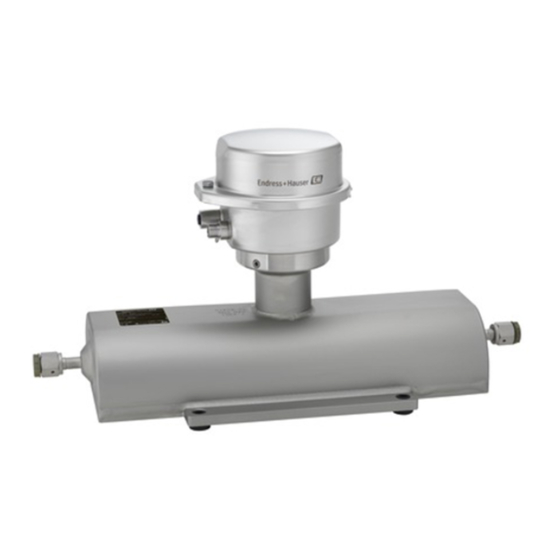
Proline Promass A 100
Coriolis flowmeter
These Instructions are Brief Operating Instructions; they do not
replace the Operating Instructions included in the scope of
supply.
For detailed information, refer to the Operating Instructions
and other documentation on the CD-ROM provided or visit
"www.endress.com/deviceviewer".
Solutions
Services
Advertisement
Table of Contents

Related Manuals for Endress+Hauser Proline Promass A 100


Summary of Contents for Endress+Hauser Proline Promass A 100
- Page 1 Solutions Services KA01144D/06/EN/02.13 71231777 Brief Operating Instructions Proline Promass A 100 Coriolis flowmeter These Instructions are Brief Operating Instructions; they do not replace the Operating Instructions included in the scope of supply. For detailed information, refer to the Operating Instructions and other documentation on the CD-ROM provided or visit "www.endress.com/deviceviewer".
-
Page 2: Table Of Contents
Table of contents Proline Promass A 100 Table of contents Document information ........... . . 3 Symbols used . -
Page 3: Document Information
Proline Promass A 100 Document information Document information Symbols used 1.1.1 Safety symbols Symbol Meaning DANGER! DANGER This symbol alerts you to a dangerous situation. Failure to avoid this situation will result in serious or fatal injury. A0011189-EN WARNING! WARNING This symbol alerts you to a dangerous situation. - Page 4 Document information Proline Promass A 100 1.1.3 Tool symbols Symbol Meaning Allen key A0011221 Open-ended wrench A0011222 1.1.4 Symbols for certain types of information Symbol Meaning Allowed Indicates procedures, processes or actions that are allowed. A0011182 Preferred Indicates procedures, processes or actions that are preferred.
-
Page 5: Basic Safety Instructions
Proline Promass A 100 Basic safety instructions Symbol Meaning Flow direction A0013441 Hazardous area Indicates a hazardous area. A0011187 Safe area (non-hazardous area) Indicates a non-hazardous area. A0011188 Basic safety instructions Requirements for the personnel The personnel must fulfill the following requirements for its tasks: ‣... -
Page 6: Workplace Safety
Verification for borderline cases: ‣ For special fluids and fluids for cleaning, Endress+Hauser is glad to provide assistance in verifying the corrosion resistance of fluid-wetted materials, but does not accept any warranty or liability as minute changes in the temperature, concentration or level of contamination in the process can alter the corrosion resistance properties. -
Page 7: Product Safety
It meets general safety standards and legal requirements. It also complies with the EC directives listed in the device-specific EC Declaration of Conformity. Endress+Hauser confirms this by affixing the CE mark to the device. -
Page 8: Product Description
Product description Proline Promass A 100 Product description Product design 3.1.1 Device version with HART, Modbus RS485 and PROFIBUS DP communication types A0017609 1 Important components of a measuring device Transmitter housing cover Main electronics module Transmitter housing Sensor In the case of the device version with Modbus RS485 intrinsically safe, the Safety Barrier Promass 100 forms part of the scope of supply. - Page 9 Proline Promass A 100 Product description 3.1.2 Device version with EtherNet/IP communication type A0017257 2 Important components of a measuring device Transmitter housing cover I/O electronics module for EtherNet/IP Main electronics module Transmitter housing Sensor Endress+Hauser...
-
Page 10: Incoming Acceptance And Product Identification
Incoming acceptance and product identification Proline Promass A 100 Incoming acceptance and product identification Incoming acceptance A0015502 A0013843 A0013695 A0015502 A0013698 A0015502 A0013699 Endress+Hauser... -
Page 11: Product Identification
Proline Promass A 100 Incoming acceptance and product identification A0015502 A0013697 If one of the conditions is not satisfied, contact your Endress+Hauser Sales Center. Product identification The following options are available for identification of the measuring device: • Nameplate specifications •... -
Page 12: Storage And Transport
Storage and transport Proline Promass A 100 Storage and transport Storage conditions Observe the following notes for storage: • Store in original packaging. • Do not remove protective covers or protective caps installed on process connections. • Protect from direct sunlight. - Page 13 Proline Promass A 100 Storage and transport A0015604 A0015605 Endress+Hauser...
-
Page 14: Installation
Installation Proline Promass A 100 Installation Installation conditions No special measures such as supports are necessary. External forces are absorbed by the construction of the device. 6.1.1 Mounting position Mounting location A0015595 Installation in down pipes However, the following installation suggestion allows for installation in an open vertical pipeline. - Page 15 Proline Promass A 100 Installation A0015596 4 Installation in a down pipe (e.g. for batching applications) Supply tank Sensor Orifice plate, pipe restriction Valve Batching tank Ø orifice plate, pipe restriction [mm] [in] [mm] [in] ¹⁄₂₄ 0.03 ¹⁄₁₂ 0.06 ¹⁄₈...
- Page 16 Installation Proline Promass A 100 Orientation The direction of the arrow on the sensor nameplate helps you to install the sensor according to the flow direction. Orientation Recommendation Vertical orientation A0015591 Horizontal orientation, transmitter head up Exception: A0015589 Horizontal orientation, transmitter...
- Page 17 Proline Promass A 100 Installation 6.1.2 Requirements from environment and process Ambient temperature range Measuring device • –40 to +60 °C (–40 to +140 °F) • –50 to +60 °C (–58 to +140 °F) (Order code for "Test, certificate", option JM Safety Barrier Promass 100 –40 to +60 °C (–40 to +140 °F)
- Page 18 Installation Proline Promass A 100 Heating options If a fluid requires that no heat loss should occur at the sensor, users can avail of the following heating options: • Electrical heating, e.g. with electric band heaters • Via pipes carrying hot water or steam •...
- Page 19 Proline Promass A 100 Installation Dimensions in SI units [mm] [mm] [in] [in] [mm] [mm] [mm] [mm] Approx.42 AF 1 ½ NPT 77.0 70.0 47.0 Approx.42 AF 1 ½ NPT 77.0 70.0 47.0 Approx.42 AF 1 ½ NPT 83.0 83.0 59.5...
- Page 20 Installation Proline Promass A 100 A0019631 Horizontal Device standing on a solid support base A0019632 Post retainer The post retainer mounting kit is used to secure the device to a pipe or post (order code for "Accessories", option PR). Endress+Hauser...
-
Page 21: Mounting The Measuring Device
Proline Promass A 100 Installation 13 mm 10 mm A0019746 5 Post retainer mounting kit 8 x hexagonal nut M8 × 0.8 4 x threaded bolt M8 × 150 1 x post retaining plate 1 x post securing plate 4 x spring washer M8 4 x hexagon bolt M6 ×... -
Page 22: Post-Installation Check
Installation Proline Promass A 100 6.2.2 Preparing the measuring device Remove all remaining transport packaging. Remove any protective covers or protective caps present from the sensor. Remove stick-on label on the electronics compartment cover. 6.2.3 Mounting the measuring device WARNING Danger due to improper process sealing! ‣... -
Page 23: Electrical Connection
Proline Promass A 100 Electrical connection Electrical connection Connection conditions 7.1.1 Required tools • For cable entries: Use corresponding tools • For securing clamp (on aluminum housing): Allen screw 3 mm • For securing screw (for stainless steel housing): open-ended wrench 8 mm •... - Page 24 Electrical connection Proline Promass A 100 Loop resistance ≤110 Ω/km Signal damping Max. 9 dB over the entire length of the cable cross-section Shielding Copper braided shielding or braided shielding with foil shield. When grounding the cable shield, observe the grounding concept of the plant.
- Page 25 Proline Promass A 100 Electrical connection Wire cross-section Maximum cable length [AWG] [ft] Cable diameter • Cable glands supplied: M20 × 1.5 with cable 6 to 12 mm (0.24 to 0.47 in) • Spring terminals: Wire cross-sections 0.5 to 2.5 mm (20 to 14 AWG) •...
- Page 26 Electrical connection Proline Promass A 100 7.1.3 Terminal assignment Safety Barrier Promass 100 Power Modbus supply RS485 Safe area Power Lift panel for bus termination Communication Safety Barrier Promass 100 Hazardous area Power Modbus supply RS485 A0016922 6 Safety Barrier Promass 100 with terminals Non-hazardous area and Zone 2/Div.
- Page 27 Proline Promass A 100 Electrical connection 4-20 mA HART with pulse/frequency/switch output 4-20 mA HART with pulse/frequency/switch output (on the device side) Assignment Coding Plug/ socket 4-20 mA HART (active) Socket 4-20 mA HART (active) Pulse/frequency/switch output (passive) Pulse/frequency/switch output (passive)
- Page 28 Electrical connection Proline Promass A 100 EtherNet/IP EtherNet/IP (on the device side) Assignment Coding Plug/ socket Socket A0016812 7.1.5 Shielding and grounding The shielding and grounding concept requires compliance with the following: • Electromagnetic compatibility (EMC) • Explosion protection • Personal protection equipment •...
- Page 29 Proline Promass A 100 Electrical connection To comply with both requirements, the fieldbus system allows three different types of shielding: • Shielding at both ends. • Shielding at one end on the feed side with capacitance termination at the field device.
- Page 30 Electrical connection Proline Promass A 100 A0019004 Controller (e.g. PLC) Segment coupler PROFIBUS DP/PA Cable shield T-box Measuring device Local grounding Bus terminator Potential matching line NOTICE In systems without potential matching, the multiple grounding of the cable shield causes mains frequency equalizing currents! Damage to the bus cable shield.
-
Page 31: Connecting The Measuring Device
Proline Promass A 100 Electrical connection If measuring device is delivered with cable glands: Observe cable specification (→ 23). Connecting the measuring device NOTICE Limitation of electrical safety due to incorrect connection! ‣ For use in potentially explosive atmospheres, observe the information in the device- specific Ex documentation. - Page 32 Electrical connection Proline Promass A 100 8 mm 8 mm 3 mm 10 (0.4) mm (in) A0017844 8 Device versions with connection examples Cable Device plug for signal transmission Device plug for supply voltage ‣ Connect the cable in accordance with the terminal assignment or the device plug pin assignment (→...
-
Page 33: Hardware Settings
Proline Promass A 100 Electrical connection L- L+ A0016804 9 Electrical connection between the transmitter and Safety Barrier Promass 100 Control system (e.g. PLC) Observe cable specification Safety Barrier Promass 100: terminal assignment (→ 26) Observe cable specification (→ 24) Non-hazardous area Non-hazardous area and Zone 2/Div. - Page 34 Electrical connection Proline Promass A 100 Addressing mode ex works Software addressing; all DIP switches for hardware addressing are set to OFF. IP address ex works DHCP server active For device addressing via software (→ 49) Setting the address...
- Page 35 Proline Promass A 100 Electrical connection Setting the address OFF ON - Software addressing - Write protection - Not used A0021265 10 Addressing using DIP switches on the I/O electronics module Disable software addressing via DIP switch 8 (OFF).
- Page 36 Electrical connection Proline Promass A 100 390 Ω DIP 1 OFF ON Bus polarisation DIP 2 220 Ω Bus termination Bus polarisation Not used DIP 3 390 Ω A0021274 11 Termination using DIP switches on the I/O electronics module (for baud rates < 1.5...
- Page 37 Proline Promass A 100 Electrical connection If the transmitter is used in the non-hazardous area or Zone 2/Div. 2 4 - Bus termination 3 - Not used 220 W 2 - Not used 1 - Write protection A0017610 12...
-
Page 38: Ensuring The Degree Of Protection
Electrical connection Proline Promass A 100 If the transmitter is used in the intrinsically safe area 220 W A0017791 13 Terminating resistor can be enabled via DIP switch in the Safety Barrier Promass 100 Ensuring the degree of protection The measuring device fulfills all the requirements for the IP66/67 degree of protection, Type 4X enclosure. -
Page 39: Post-Connection Check
Proline Promass A 100 Electrical connection A0013960 Insert dummy plugs into unused cable entries. Post-connection check Are cables or the device undamaged (visual inspection)? Do the cables comply with the requirements (→ 23)? Do the cables have adequate strain relief? ... -
Page 40: Operation Options
Operation options Proline Promass A 100 Operation options Structure and function of the operating menu 8.1.1 Structure of the operating menu Operating menu for operators and maintenances Language Operation Setup Diagnostics Operating menu for experts Expert A0014058-EN 8.1.2 Operating philosophy The individual parts of the operating menu are assigned to certain user roles. - Page 41 Proline Promass A 100 Operation options 8.2.2 Prerequisites Hardware Connecting cable Standard Ethernet cable with RJ45 connector Computer RJ45 interface Measuring device Web server must be enabled; factory setting: ON Software of the computer Web browsers supported • Microsoft Internet Explorer 7.x, 8.x, 9.x •...
- Page 42 Operation options Proline Promass A 100 No. 10 to ON, restart the device and enter the default setting for the IP address: 192.168.1.212. The login page appears. Device tag Webserv.language English Ent. access code Access stat.tool Maintenance A0017362 Device tag (→ 49) Picture of device 8.2.4...
- Page 43 Proline Promass A 100 Operation options 8.2.5 User interface A0017757-EN Picture of device Function row with 6 functions Device tag Header Working area Navigation area Header The following information appears in the header: • Device tag (→ 49) • Device status with status signal •...
-
Page 44: Access To The Operating Menu Via The Operating Tool
Operation options Proline Promass A 100 Access to the operating menu via the operating tool For detailed information about access to the operating menu via operating tool, refer to the Operating Instructions for the device on the CD-ROM provided 8.3.1... - Page 45 Proline Promass A 100 Operation options 8.3.2 Via service interface (CDI-RJ45) A0016926 14 Connection for the order code for "Output", option B: 4-20 mA HART, pulse/frequency/ switch output Service interface (CDI -RJ45) of the measuring device with access to the integrated Web server Computer with Web browser (e.g.
- Page 46 Operation options Proline Promass A 100 A0016940 16 Connection for order code for "Output", option N: EtherNet/IP Service interface (CDI -RJ45) and EtherNet/IP interface of the measuring device with access to the integrated Web server Computer with Web browser (e.g. Internet Explorer) for accessing the integrated device Web server or with "FieldCare"...
- Page 47 Proline Promass A 100 Operation options A0016961 Ethernet network Automation system, e.g. "RSLogix" (Rockwell Automation) Workstation for measuring device operation: with Add-on Profile Level 3 for "RSLogix 5000" (Rockwell Automation) or with Electronic Data Sheet (EDS) Computer with Web browser (e.g. Internet Explorer) for accessing the integrated device Web server or with "FieldCare"...
-
Page 48: System Integration
System integration Proline Promass A 100 For device version with Modbus RS485 communication type Via service interface (CDI) and "FieldCare" operating tool Start FieldCare and launch the project. In the network: Add a device. The Add device window opens. -
Page 49: Configuring The Device Address Via Software
Proline Promass A 100 Commissioning 10.3 Configuring the device address via software Applies only to device version with EtherNet/IP communication type Software addressing is carried out in the Communication submenu. Navigation path "Setup" menu → Communication When delivered, the measuring device has the following factory settings:... -
Page 50: Protecting Settings From Unauthorized Access
Commissioning Proline Promass A 100 Parameter overview with brief description Parameters Description User entry Factory setting Device tag Enter tag for measuring Max. 32 characters, such Promass point. as letters, numbers or special characters (e.g. @, %, /). 10.6 Protecting settings from unauthorized access... - Page 51 Proline Promass A 100 Commissioning 10.6.2 Write protection via write protection switch The write protection switch makes it possible to block write access to the entire operating menu with the exception of the following parameters: • External pressure • External temperature •...
- Page 52 Commissioning Proline Promass A 100 OFF ON - Write protection - Default Ethernet network settings IP 192.168.1.212 A0017915 For device version with PROFIBUS DP communication type OFF ON - Software addressing - Write protection - Not used A0021262 ‣ Setting the write protection switch on the electronics module to the ON position enables the hardware write protection.
-
Page 53: Diagnostic Information
Proline Promass A 100 Diagnostic information Diagnostic information Any faults detected by the measuring device are displayed on the home page of the operating tool once the connection has been established and on the home page of the web browser once the user has logged on. - Page 56 www.addresses.endress.com...