Table of Contents
Advertisement
Available languages
Available languages
Quick Links
Istruzioni per installazione, uso e manutenzione
Installation, use and maintenance instructions
Bruciatori di gas ad aria soffiata
I
Forced draught gas burners
GB
Funzionamento bistadio
Two stage operation
CODICE - CODE
3761391
3761491
MODELLO - MODEL
BS3D F
BS4D F
TIPO - TYPE
913 T2
914 T2
2903387 (1) - 09/2011
Advertisement
Table of Contents

Related Manuals for Riello GULLIVER BS4D F


Summary of Contents for Riello GULLIVER BS4D F
- Page 1 Istruzioni per installazione, uso e manutenzione Installation, use and maintenance instructions Bruciatori di gas ad aria soffiata Forced draught gas burners Funzionamento bistadio Two stage operation CODICE - CODE MODELLO - MODEL TIPO - TYPE 3761391 BS3D F 913 T2 3761491 BS4D F 914 T2...
-
Page 3: Table Of Contents
INDICE DESCRIZIONE DEL BRUCIATORE ..........2 Materiale a corredo. -
Page 4: Descrizione Del Bruciatore
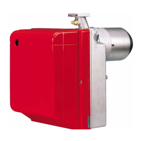
DESCRIZIONE DEL BRUCIATORE Bruciatore di gas con funzionamento bistadio. Il bruciatore risponde al grado di protezione IP X0D (IP 40) secondo EN 60529. Rampa gas conforme a EN 676. Fig. 1 1 – Pressostato aria 6 – Flangia con schermo isolante 2 –... -
Page 5: Dati Tecnici
KIT GPL E’ disponibile un kit speciale che montato sulla testa di combustione consente ai bruciatori, previsti per fun- zionamento a gas naturale, di bruciare GPL. Per l’installazione del “kit GPL” fare riferimento alle istruzioni che l’accompagnano. Il kit deve essere installato in conformità alle leggi e alle normative locali. KIT TESTA DI COMBUSTIONE ALTERNATIVA Il kit può... -
Page 6: Dimensioni
Per gas della famiglia 3 (GPL) richiedere kit a parte. PAESE AT - IT - DK - CH GB - IE LU-PL CATEGORIA GAS II2H3B/P II2H3P II2ELL3B/P II2Er3P II2L3B/P II2E3B/P I2E(R)B, I3P – – – – – – PRESSIONE – –... -
Page 7: Campi Di Lavoro
2.3 CAMPI DI LAVORO 913T2 914T2 EN 676 -0,8 EN 746-2 -1,6 -2,0 D4448 50.000 100.000 150.000 200.000 kcal/h Potenza termica 913T2 914T2 LRV 92 -1,0 EN 746-2 -2,0 D4496 50.000 100.000 150.000 200.000 kcal/h Potenza termica Nel modello tipo 914T2, per garantire il funzionamento con una potenzialità da 220 - 246 kW, togliere il fonoassorbente pretranciato per liberare le feritoie addizionali di ingresso d’aria sul cofano. -
Page 8: Installazione
CORRELAZIONE TRA PRESSIONE DEL GAS E POTENZIALITÀ Per avere la massima potenzialità occorrono 10,5 mbar, relativamente al modello 913T2, misurati al manicotto (M2, vedi cap. 3.6, pag. 8) con camera di combustione a 0 mbar e gas G20 – Pci = 10 kWh/m 3 (8.570 kcal/m 3 ). 250 kW D8113 50.000... -
Page 9: Fissaggio Alla Caldaia
3.2 FISSAGGIO ALLA CALDAIA Per installare il bruciatore alla caldaia è necessario effettuare le seguenti operazioni: Allargare, se necessario, i fori dello schermo isolante (3, Fig. 3). Fissare alla portina della caldaia (1) la flangia (5) mediante le quattro viti (4) e (se necessario) i dadi (2) interponendo lo schermo isolante (3) ma tenendo allentata una delle due viti superiori (4), (vedi Fig. -
Page 10: Rampa Gas
3.4 RAMPA GAS, (secondo EN 676) La rampa gas viene fornita a parte e per la sua regolazione vedere le istruzioni che l’accompagnano. RAMPA GAS ATTACCHI BRUCIATORE IMPIEGO ABBINABILE TIPO CODICE INGRESSO USCITA Gas naturale 150 kW e GPL MB ZRDLE 407 B01 3970541 BS3D F - BS4D F... -
Page 11: Collegamenti Elettrici
3.7 COLLEGAMENTI ELETTRICI 3.7.1 COLLEGAMENTI ELETTRICI STANDARD ESEGUITO IN FABBRICA A CURA DELL’INSTALLATORE D7198 LEGENDA Interruttore – Segnalazione funz. 2° stadio – Segnalazione di blocco a generale – Condensatore distanza (230V - 0,5 A max.) CN1 – Connettore sonda ionizz. T6A –... -
Page 12: Collegamenti Elettrici Con Controllo Tenuta Valvole (Dungs Vps 504)
3.7.2 COLLEGAMENTI ELETTRICI CON CONTROLLO TENUTA VALVOLE (DUNGS VPS 504) LEGENDA B5 – Segnalazione funz. 2° stadio h1 – Contaore 1° stadio h2 – Contaore 2° stadio PG – Pressostato gas minima S3 – Segnalazione di blocco a distanza (230V - 0,5A max.) T6A –... -
Page 13: Funzionamento
FUNZIONAMENTO POTENZA ALL’ACCENSIONE Fig. 10 L’accensione deve avvenire a potenza ridotta e non superiore ai 120 kW. Per misurare la potenza all'accensione: – Scollegare il connettore (CN1) sul cavo della sonda di ionizzazione (vedi collegamenti elettrici a pag. 9); il bruciatore si accende e va in blocco dopo il tempo di sicurezza (3s). -
Page 14: Regolazione Servomotore Serranda Aria
ESTRAZIONE GRUPPO TESTA, (vedi Fig. 10) Per l’estrazione del gruppo testa eseguire le seguenti operazioni: Estrarre il gruppo porta testa (1) dopo aver tolto le viti (7), sconnesso i collegamenti (3 e 5), sfilato il tubetto (4) e allentato le viti (8). Si raccomanda di non alterare la posizione di regolazione staffa–gomito nella fase di smontaggio. -
Page 15: Pressostato Aria
4.5 PRESSOSTATO ARIA Eseguire la regolazione del pressostato aria dopo aver effettuato tutte le altre regolazioni del bruciatore con il pressostato aria regolato a inizio scala. Con il bruciatore funzionante alla potenza richiesta, ruotare la manopola lentamente in senso orario fino al blocco del bruciatore. Ruotare quindi in senso antiorario la manopola di una tacca e ripetere l’avviamento del bruciatore per verificarne la regolarità. -
Page 16: Manutenzione
MANUTENZIONE Prima di effettuare qualsiasi operazione di pulizia o controllo, togliere l’alimentazione elettrica al bru- ciatore agendo sull’interruttore generale dellíimpianto e chiudere la valvola di intercettazione del gas. Il bruciatore richiede una manutenzione periodica, che deve essere eseguita da personale abilitato e in con- formità... -
Page 17: Diagnostica Visiva Apparecchiatura
5.1 DIAGNOSTICA VISIVA APPARECCHIATURA L’apparecchiatura in dotazione ha una funzione diagnostica attraverso la quale è possibile individuare le eventuali cause di mal funzionamento (segnalazione: LED ROSSO). Per utilizzare tale funzione, è necessario premere il pulsante di sblocco per almeno 3 secondi dall’istante di messa in sicurezza (blocco). -
Page 18: Anomalie / Rimedi
ANOMALIE / RIMEDI Si elencano alcune cause e i possibili rimedi a una serie di anomalie che potrebbero verificarsi e portare ad un mancato o non regolare funzionamento del bruciatore. Un’anomalia, nel funzionamento nella maggior parte dei casi, porta alla accensione della segnalazione all’interno del pulsante di sblocco dell’apparecchia- tura di comando e controllo (4, Fig. -
Page 19: Anomalie In Funzionamento
ANOMALIE POSSIBILE CAUSA RIMEDIO Verificare la pressione in rete e/o re- Le elettrovalvole fanno passare golare l’elettrovalvola come indicato in troppo poco gas. questo manuale. Le elettrovalvole sono difettose. Procedere ad una loro sostituzione. Il bruciatore va in bloc- co dopo la fase di pre- Verificare il corretto inserimento dei ventilazione perché... -
Page 20: Avvertenze E Sicurezza
AVVERTENZE E SICUREZZA Al fine di garantire una combustione col minimo tasso di emissioni inquinanti, le dimensioni ed il tipo di ca- mera di combustione del generatore di calore, devono corrispondere a valori ben definiti. È pertanto consigliato consultare il Servizio Tecnico di Assistenza prima di scegliere questo tipo di brucia- tore per l’abbinamento con una caldaia. - Page 21 INDEX BURNER DESCRIPTION ............2 Burner equipment .
- Page 22 BURNER DESCRIPTION Two stage gas burner. The burner meets protection level of IP X0D (IP 40) as EN 60529. Gas train according to EN 676. Fig. 1 1 – Air pressure switch 6 – Flange with insulating gasket 2 –...
- Page 23 LPG KIT There is a special kit available that, when mounted on the combustion head, enables burners designed to run off natural gas to burn LPG instead. Refer to the instructions supplied with the “LPG kit” for installation. The kit must be installed in conformity with laws and local regulations. ALTERNATIVE COMBUSTION HEAD KIT The kit can be used to avoid combustion instability that might be encountered in special applications.
- Page 24 For gas family 3 (LPG) ask for separate kit. COUNTRY AT - IT - DK - CH GB - IE LU-PL GAS CATEGORY II2H3B/P II2H3P II2ELL3B/P II2Er3P II2L3B/P II2E3B/P I2E(R)B, I3P – – – – – – – – – PRESSURE –...
- Page 25 2.3 FIRING RATES 913T2 914T2 EN 676 -0,8 EN 746-2 -1,6 -2,0 50.000 100.000 150.000 200.000 kcal/h Thermal power 913T2 914T2 LRV 92 -1,0 EN 746-2 -2,0 50.000 100.000 150.000 200.000 kcal/h Thermal power In the 914T2 type, in order to guarantee the working with an output of 220 - 246 kW, remove the blank deadening to free the supplementary slits of the air inlet on the cover.
- Page 26 CORRELATION BETWEEN GAS PRESSURE AND BURNER OUTPUT To obtain the maximum output, a gas head pressure of 10.5 mbar, relatively to 913T2 model, is measured (M2, see chapter 3.6, page 8) with the combustion chamber at 0 mbar using gas G20 with a net heat value of 10 kWh/m (8.570 kcal/m 250 kW...
- Page 27 3.2 BOILER FIXING To fit the burner to the boiler it is necessary to carry out the following: Widen, if necessary, the insulating gasket holes (3, Fig. 3). Fix the flange (5) to the boiler door (1) using four screws (4) and (if necessary) the nuts (2) interposing the insulating gasket (3) but keep unloosing one of the two upper screws (4) (see Fig.
- Page 28 3.4 GAS TRAIN, (as EN 676) The gas train is supplied separately, for its adjustment see the enclosed instructions. GAS TRAIN CONNECTIONS MATCHED BURNER TYPE CODE INLET OUTLET Natural gas 150kW and LPG MB ZRDLE 407 B01 3970541 BS3D F - BS4D F Rp 3/4 Flange 3 MB ZRDLE 410 B01...
- Page 29 3.7 ELECTRICAL WIRING 3.7.1 STANDARD ELECTRICAL WIRING CARRIED-OUT IN THE FACTORY TO BE DONE BY THE INSTALLER D7198 KEY TO LAY-OUT Main switch – 2 nd stage working signal – Remote lock-out signal – Capacitor (230V - 0.5 A max.) CN1 –...
- Page 30 3.7.2 ELECTRICAL WIRING WITH GAS LEAK CONTROL DEVICE (DUNGS VPS 504) KEY TO LAY-OUT B5 – 2 stage lock-out signal h1 – 1 stage Hour counter h2 – 2 stage Hour counter PG – Min. gas pressure switch S3 – Remote lock-out signal (230V - 0.5 A max.) T6A –...
- Page 31 WORKING FIRING OUTPUT Fig. 10 The firing must occur at reducer output and not higher than 120 kW. In order to measure the firing output: – Disconnect the connector (CN1) on the ioniza- tion probe cable (see electrical wiring at page 9);...
- Page 32 REMOVING HEAD ASSEMBLY, (see Fig. 10) To remove the head assembly, carry out the following operations: Remove the head-holder assembly (1), after taking away the screws (7), disconnect the connections (3 and 5), extract the small tube (4) and loosen the screws (8). Do not modify the setting position of the bracket-elbow during the disassembly.
- Page 33 4.5 AIR PRESSURE SWITCH The air pressure switch is set after all other adjustments have been made. Begin with the switch at the lowest setting. With the burner working at the required output, adjust the dial clockwise, increasing its value until the burner shuts down.
- Page 34 MAINTENANCE Disconnect the electric supply to the burner by switching off the main power switch and close the gas shut-off valve before maintaining or checking the system. The burner requires scheduled maintenance that must be carried out by qualified personnel and in compli- ance with local legislation.
- Page 35 5.1 VISUAL DIAGNOSTIC CONTROL BOX The control box has a diagnostic function that can identify the likely causes of any malfunctions (indicator: RED LED). In order to be able to use this function, press and hold the reset button for at least 3 seconds from when the appliance is made safe (lock-out).
- Page 36 FAULTS / SOLUTIONS Here below you can find some causes and the possible solutions for some problems that could cause a failure to start or a bad working of the burner. A fault usually makes the lock-out lamp light which is situ- ated inside the reset button of the control box (4, Fig.
- Page 37 FAULTS POSSIBLE CAUSES SOLUTION Check the pressure in the network and/ The solenoid valves is passing too lit- or adjust the solenoid valve according to tle gas. the instructions of this manual. The solenoid valves are defective. Change them. The burner lock s out a f t e r t h e p r e p u r g e Check the right insertion of the connectors.
- Page 38 SAFETY WARNINGS The dimension of the boiler’s combustion chamber must respond to specific values, in order to guarantee a combustion with the lowest polluting emissions rate. The Technical Service Personnel will be glad to give you all the imformation for a correct matching of this burner to the boiler.
- Page 40 RIELLO S.p.A. I-37045 Legnago (VR) Tel.: +39.0442.630111 http:// www.riello.it http:// www.rielloburners.com Con riserva di modifiche - Subject to modifications...