Endress+Hauser SpectraSensors SS2100i-1 Hardware Installation And Maintenance Manual
Tdl gas analyzer
Hide thumbs
Also See for SpectraSensors SS2100i-1:
- Operating instructions manual (64 pages) ,
- Overview manual (47 pages) ,
- Safety manual (36 pages)
Table of Contents
Advertisement
Quick Links
Products
Solutions
Services
4900002224 Rev E
Hardware Installation and Maintenance Manual
SS2100i-1 TDL Gas Analyzer
ATEX/IECEx: Zone 1
Copyright © 2020 SpectraSensors, Inc. No part of this manual may be reproduced in whole or
in part without the express written permission of SpectraSensors, Inc. SpectraSensors reserves
the right to change product design and specifications at any time without prior notice.
Advertisement
Table of Contents

Related Manuals for Endress+Hauser SpectraSensors SS2100i-1


Summary of Contents for Endress+Hauser SpectraSensors SS2100i-1
- Page 1 Products Solutions Services 4900002224 Rev E Hardware Installation and Maintenance Manual SS2100i-1 TDL Gas Analyzer ATEX/IECEx: Zone 1 Copyright © 2020 SpectraSensors, Inc. No part of this manual may be reproduced in whole or in part without the express written permission of SpectraSensors, Inc. SpectraSensors reserves the right to change product design and specifications at any time without prior notice.
- Page 3 Product/Firmware Matrix HC12 PRODUCT MODEL Firmware Firmware Firmware SS2100, SS2100a, Not used Used for Used for non- SS2100i-1, SS2100i-2 differential differential analyzers analyzers 2-Pack/3-Pack Used on right- Used on left‐ Not used side analyzer side analyzer electronics electronics SS1000, SS500, SS500e, Used Not used Not used SS500XP, SS2000, SS2000e, SS2000XP, SS3000, SS3000e...
-
Page 5: Table Of Contents
ABLE OF ONTENTS List of Figures ..........iii List of Tables . - Page 6 SS2100i-1 Gas Analyzer Appendix A: Specifications Exd Accessory Conditions of Use ........A-2 Appendix B: Maintenance &...
-
Page 7: List Of Figures
IST OF IGURES Figure 1–1. Schematic of a typical tunable diode laser absorption spectrometer ........1-6 Figure 1–2. - Page 8 SS2100i-1 Gas Analyzer Figure A–1. Outline and mounting diagram ......A-4 Figure B–1. Measurement cell types ....... B-4 Figure B–2.
- Page 9 IST OF ABLES Table 1–1. Fuse specifications for 240 VAC systems ....1-17 Table 1–2. Fuse specifications for 120 VAC systems ....1-18 Table 3–1.
- Page 10 SS2100i-1 Gas Analyzer THIS PAGE INTENTIONALLY LEFT BLANK 4900002224 rev. E 12-18-20...
-
Page 11: How To Use This Manual
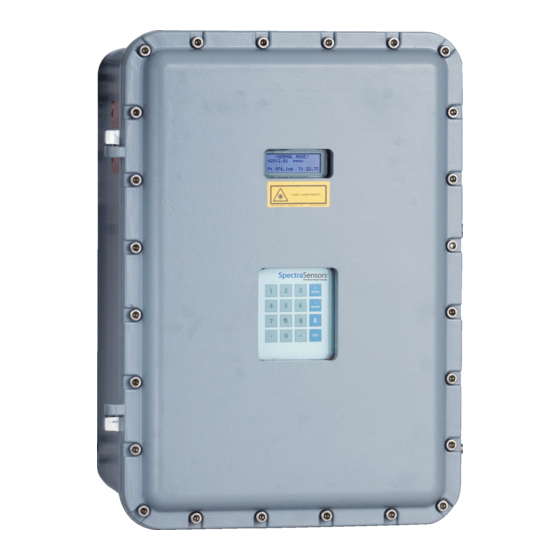
1 - I NTRODUCTION SpectraSensors SS2100i-1 products are high-speed, diode-laser based extractive analyzers designed for reliable monitoring of very low (trace) to standard concentrations of specific components in various background gases. It is important to closely review the installation and operation sections of this manual to ensure the analyzer performs as specified. -
Page 12: Safety Warning Label
SS2100i-1 Gas Analyzer Safety warning label The warning label shown below will be affixed to the front side of all analyzer enclosures that contain sample gas. Hazards may vary by stream composition. One or more of the following conditions may apply. Flammable. -
Page 13: Equipment Labels
Introduction Equipment labels Warning statement for hazardous voltage. Contact may cause electric shock or burn. Turn off and lock out system before servicing. Failure to follow all directions may result in damage or malfunction of the analyzer. Maximum voltage and current specifications for the fuse closest to label. -
Page 14: Instructional Symbols
Laboratory (JPL) for the purpose of commercializing space-proven measurement technologies initially developed at JPL. SpectraSensors was acquired by the Endress + Hauser Group in 2012. Manufacturer Address SpectraSensors, Inc. An Endress+Hauser Company 11027 Arrow Route Rancho Cucamonga, CA 91730 United States www.spectrasensors.com –... -
Page 15: About The Gas Analyzers
Introduction About the Gas Analyzers The SS2100i-1 analyzers are tunable diode laser (TDL) absorption spectrometers operating in the near- to short-wavelength infrared. Each compact sensor consists of a TDL light source, sample cell and detector specifically configured to enable high sensitivity measurement of a particular component within the presences of other gas phase constituents in the stream. -
Page 16: Figure 1-1. Schematic Of A Typical Tunable Diode Laser Absorption
SS2100i-1 Gas Analyzer OPTICAL HEAD DETECTOR OPTICAL HEAD LASER LASER DETECTOR WINDOW OUTLET WINDOW INLET PRESSURE SENSOR PRESSURE SENSOR INLET OUTLET FAR MIRROR FAR MIRROR 0.8 m MEASUREMENT CELL 8/28 m MEASUREMENT CELL Figure 1–1 Schematic of a typical tunable diode laser absorption spectrometer laser is tuned on-resonance versus off-resonance is directly proportional to the number of molecules of that particular species in the beam path, or... -
Page 17: Figure 1-2 Typical Raw Signal From A Laser Diode Absorption Spectrometer With And Without Mirror Contamination
Introduction Incident Energy I () Raw Signal, I() Raw Signal, I() (Contaminated Mirrors) Resonance Absorption Wavelength [a.u.] Figure 1–2 Typical raw signal from a laser diode absorption spectrometer with and without mirror contamination 0.99 0.98 0.97 0.96 Normalized Absorption Signal 0.95 Wavelength [a.u.] Figure 1–3 Typical normalized absorption signal... -
Page 18: Differential Tdlas
SS2100i-1 Gas Analyzer Differential TDLAS Similar to TDLAS, this SpectraSensors technology involves subtracting two spectrums from one another. A “dry” spectrum, a response from the sample when the analyte of interest has been completely removed, is subtracted from the “wet” spectrum, a response from the sample when the analyte is present. The remainder is a spectrum of the pure analyte. -
Page 19: Getting Familiar With The Ss2100I-1
Introduction All SpectraSensors TDL gas analyzers employ the same design and hardware platform. Measuring different trace gases in various mixed hydrocarbon background streams is accomplished by selecting a different optimum diode laser wavelength between 700 to 3000 nm, which provides the least amount of sensitivity to background stream variations. -
Page 20: Figure 1-6 Upper And Lower Levels Of Analyzer Assembly (8/28 M Sample Cell)
SS2100i-1 Gas Analyzer On the front cover, the keypad and LCD display serve as the user interface to the analyzer. Power and signal connections are made via access ports on the bottom of the analyzer. Tube fittings on the right side are for sample supply and return connections. -
Page 21: Figure 1-7. Upper And Lower Levels Of Analyzer Assembly
Introduction Figure 1–7 Upper and lower levels of analyzer assembly (0.8 m sample cell) – Hardware Installation and Maintenance Manual... -
Page 22: Figure 1-8. Upper And Lower Levels Of Analyzer Assembly
SS2100i-1 Gas Analyzer Figure 1–8 Upper and lower levels of analyzer assembly (0.1 m sample cell) – 4900002224 rev. E 12-18-20... -
Page 23: Figure 1-9 Components On Electronics Panel Assembly (Upper Level)
Introduction 4-20mA AI 4-20mA AO TEMPERATURE BOARD BOARD CONTROL BOARD FUSE (F3) ANALYZER POWER SUPPLY HIGH TEMPERATURE ARM9 CONTROL LIMIT ELECTRONICS THERMOSTAT SET AT 70 °C RELAYS RS-232 TO RS-485 CONVERTER AUXILIARY POWER AC LINE FILTER SUPPLY GROUND TERMINAL BLOCKS FUSES (F4-F10) TERMINAL BLOCKS... -
Page 24: Figure 1-10 Components On Sample Cell Panel Assembly (8/28 M Sample Cell) (Lower Level)
SS2100i-1 Gas Analyzer TRANSITION PLATE HEATER THERMISTOR THERMISTOR ASSEMBLY MEASUREMENT CELL TEMPERATURE CONTROLLER AC TERMINAL BLOCK FOR HEATER PRESSURE SENSOR SOLID-STATE RELAY Figure 1–10 Components on sample cell panel assembly (8/28 m sample cell) (Lower level) – 4900002224 rev. E 12-18-20... -
Page 25: Figure 1-11 Components On Sample Cell Panel Assembly (0.8 M Sample Cell) (Lower Level)
Introduction TRANSITION PLATE THERMISTOR PRESSURE SENSOR HEATER MEASUREMENT CELL THERMISTOR ASSEMBLY TEMPERATURE CONTROLLER AC TERMINAL BLOCK FOR HEATER SOLID-STATE RELAY Figure 1–11 Components on sample cell panel assembly (0.8 m sample cell) (Lower level) – Hardware Installation and Maintenance Manual... -
Page 26: Figure 1-12 Components On Sample Cell Panel Assembly (0.1 M Sample Cell) (Lower Level)
SS2100i-1 Gas Analyzer TRANSITION PLATE PRESSURE SENSOR THERMISTOR HEATER MEASUREMENT CELL SAMPLE TEMPERATURE THERMISTOR AC TERMINAL BLOCK FOR SOLID STATE HEATER RELAY TEMPERATURE CONTROLLER Figure 1–12 Components on sample cell panel assembly (0.1 m sample cell) (Lower level) On the upper level (electronics panel assembly), the analyzer power supply provides power to the analyzer control electronics and relays controlling valves. -
Page 27: Table 1-1 Fuse Specifications For 240 Vac Systems
Introduction The relay control board serves as the interface between the analyzer control electronics and the relays whereas the temperature control board controls the thermo-electric (TEC) cooler that maintains the laser temperature inside the sample cell optical head. An optically-isolated RS-232 to RS-422/485 converter takes the inherent RS-232 serial output of the laser control electronics and converts it to RS-485. -
Page 28: Special Safety Symbols Used On The Equipment
SS2100i-1 Gas Analyzer Table 1–2 Fuse specifications for 120 VAC systems Drawing Description Rating Reference Miniature Fuse, 5 x 20 mm, Time Delay 250 VAC/1.6 A Miniature Fuse, 5 x 20 mm, Time Delay 250 VAC/0.5 A Miniature Fuse, 5 x 20 mm, Time Delay 250 VAC/0.1 A , F6 , F8... - Page 29 Introduction GENERAL WARNING - Failure to follow all directions may result in damage or malfunction of the analyzer. PROTECTIVE EARTH GROUND - Symbol indicates the connection point of the ground wire from the main power source. FUNCTIONAL EARTH GROUND - Symbol indicates grounding points intended primarily for troubleshooting.
-
Page 30: Figure 1-13 Label Placement On Exterior Of Enclosure
SS2100i-1 Gas Analyzer MANUFACTURER LABEL CLASS 1 LASER PRODUCT LABEL CHASSIS GROUND LABEL Figure 1–13 Label placement on exterior of enclosure – 4900002224 rev. E 12-18-20... -
Page 31: Figure 1-14. Label Placement On Electronics Panel Assembly
Introduction ENERGIZED GENERAL WARNING LABEL FUSE WARNING LABEL ELECTRIC SHOCK WARNING LABEL GENERAL WARNING LABEL ELECTRIC SHOCK WARNING LABEL GENERAL WARNING GENERAL LABELS WARNING LABEL ELECTRIC ELECTRIC SHOCK SHOCK WARNING WARNING LABEL LABEL FUNCTIONAL FUSE EARTH GROUND RATING LABEL LABEL FUNCTIONAL EARTH PROTECTIVE GROUND LABEL... -
Page 32: Figure 1-15 Label Placement On Sample Cell Panel Assembly (8/28 M Sample Cell) (Lower Level)
SS2100i-1 Gas Analyzer MEASUREMENT CELL RATING LABEL DO NOT REMOVE WARNING LABEL CLASS 3B LASER PRODUCT LABEL ELECTRIC SHOCK WARNING LABEL CLASS 3B LASER WARNING LABEL Figure 1–15 Label placement on sample cell panel assembly (8/28 m sample cell) (Lower level) –... -
Page 33: Figure 1-16 Label Placement On Sample Cell Panel Assembly (0.8 M Sample Cell) (Lower Level)
Introduction CLASS 3B LASER PRODUCT LABEL MEASUREMENT CELL RATING LABEL DO NOT REMOVE WARNING LABEL ELECTRIC SHOCK WARNING LABEL CLASS 3B LASER WARNING LABEL Figure 1–16 Label placement on sample cell panel assembly (0.8 m sample cell) (Lower level) – Hardware Installation and Maintenance Manual... -
Page 34: Figure 1-17 Label Placement On Sample Cell Panel Assembly (0.1 M Sample Cell) (Lower Level)
SS2100i-1 Gas Analyzer CLASS 3B LASER PRODUCT LABEL MEASUREMENT CELL RATING LABEL DO NOT REMOVE WARNING LABEL ELECTRIC SHOCK WARNING LABEL Figure 1–17 Label placement on sample cell panel assembly (0.1 m sample cell) (Lower level) – 4900002224 rev. E 12-18-20... -
Page 35: Potential Risks Affecting Personnel
2 - S AFETY Potential Risks Affecting Personnel This section addresses the appropriate actions to undertake when faced with hazardous situations during or before service of the analyzer. It is not possible to list all potential hazards within this document. The user is responsible for identifying and mitigating any potential hazards present when servicing the analyzer. -
Page 36: Electrocution Hazard
SS2100i-1 Gas Analyzer Electrocution hazard 1. Shut off power at the main disconnect external to the analyzer. Complete this action before performing any service that requires working near the main input power or disconnecting any wiring or other electrical components. 2. Open enclosure door. If service must be performed with power engaged (gain adjustment, etc.): 1. -
Page 37: What Should Be Included In The Shipping Box
μH/Ω. The maximum total loop capacitance shall be 0.27 microfarads. What Should be Included in the Shipping Box The contents of the crate should include: • The SpectraSensors SS2100i-1 analyzer • Document CD or USB; includes this Operator’s Manual and the AMS100 software and instruction •... -
Page 38: Hardware
SS2100i-1 Gas Analyzer Hardware • Mounting hardware Mounting hardware used for wall-mounting the SS2100i-1 must be able to support four times the weight of the instrument (86 kg [190 lbs]) not including the sample system). • Stainless steel tubing (SpectraSensors recommends using 1/4” O.D. x 0.035”... -
Page 39: To Mount The Analyzer
Installation move the analyzer. If the analyzer is to be lifted by hand, designate multiple individuals to lift by the mounting brackets, and distribute the weight among personnel to avoid injury. To mount the analyzer 1. Select a suitable location to mount the analyzer. Choose a shaded area or use an optional analyzer hood (or equivalent) to minimize sun exposure. -
Page 40: Connecting The Solenoid Valves
SS2100i-1 Gas Analyzer All cover screws must always be tightened completely and may be replaced only with screws of the same type (ISO 4762/DIN 912) and material (Stainless Steel Grade A2-70). Ultimate Racing UR 0905 Copper Anti-Seize Lubricant or equivalent on cover screw threads to prevent galling unless glands are used. -
Page 41: Figure 3-1 Basic Differential System With Two Solenoid Valves
Installation CELL SCRUBBER SCRUBBER EFFICIENCY INDICATOR SAMPLE SAMPLE SUPPLY RETURN Figure 3–1 Basic differential system with two solenoid valves – Hardware Installation and Maintenance Manual... -
Page 42: Figure 3-2 Preferred Basic Differential System With One Solenoid Valve Driving Two Pneumatic Valves
SS2100i-1 Gas Analyzer INSTRUMENT AIR SUPPLY CELL SCRUBBER SCRUBBER EFFICIENCY INDICATOR SAMPLE SAMPLE SUPPLY RETURN Figure 3–2 Preferred basic differential system with one solenoid valve driving two pneumatic valves – 4900002224 rev. E 12-18-20... -
Page 43: Figure 3-3 Differential System With Single Autovalidation Requiring Two Solenoid Valves Driving Three Pneumatic Valves
Installation VENT VENT INSTRUMENT AIR SUPPLY CELL CELL FLOW FROM SV1 VAL GAS SUPPLY SCRUBBER FROM SV2 SCRUBBER EFFICIENCY INDICATOR SAMPLE SUPPLY SAMPLE RETURN Figure 3–3 Differential system with single autovalidation requiring two solenoid valves driving three pneumatic valves – Hardware Installation and Maintenance Manual... -
Page 44: Figure 3-4 Differential System With Dual Autovalidation Requiring Four Solenoid Valves Driving Eight Pneumatic Valves
SS2100i-1 Gas Analyzer CELL SAMPLE SCRUBBER SUPPLY SCRUBBER EFFICIANCY VALIDATION 1 INDICATOR SUPPLY VALIDATION 2 SUPPLY SAMPLE RETURN INSTRUMENT AIR SUPPLY VENTS VENTS Figure 3–4 Differential system with dual autovalidation requiring four solenoid valves driving eight pneumatic valves – 4900002224 rev. E 12-18-20... -
Page 45: To Connect The Solenoid Valves
Installation on page 3–7, whereas autovalidation with two gases requires four solenoids, as shown in Figure 3–4 on page 3–8. Certified glands and cables should be used where appropriate in compliance with local regulations. Hazardous voltage and risk of electric shock. Turn off and lock out system power before opening the electronics enclosure and making any connections. -
Page 46: Connecting Electrical Power To The Analyzer
SS2100i-1 Gas Analyzer Table 3–1 Terminal block (X2) solenoid valve connections Relay Rating Figure Description Terminal Scrubber Solenoid 3–1 No Connection 3–2 Scrubber Solenoid Scrubber Solenoid 3–3 Val 1 Solenoid Scrubber Solenoid Main/Val Solenoid 3–4 Val 1 Solenoid Val 2 Solenoid 5. -
Page 47: Protective Chassis And Ground Connections
Installation Certified compound barrier seal glands shall be used; cables used shall comply with electrical code, standards, suitable for the glands and meet the local regulations. Use copper conductors only. The electrical power and the signal wiring for the SS2100i-1 analyzer is connected through the conduit hub at the bottom of the electronics enclosure. -
Page 48: To Connect Electrical Power To The Analyzer
SS2100i-1 Gas Analyzer GROUND CONNECTION Figure 3–5 Enclosure door - inside view To connect electrical power to the analyzer 1. Open the analyzer enclosure cover according to the procedure under “To open the analyzer enclosure cover” on page 3-3 to gain access to the field interface terminal block. 2. - Page 49 Installation 5. Strip back the jacket and/or insulation of the wires just enough to connect to the power terminal blocks (X1). 6. Attach the neutral and hot wires to the power terminal blocks by connecting the neutral wire to terminal X1-2, the hot wire to terminal X1-1, as shown in Figure 3–6 on page 3–14.
-
Page 50: Figure 3-6 Field Interface Terminal Block For Connection Of Input Power And Input/Output Signals
FROM HEATER GROUND STUD FROM ENCLOSURE DOOR GROUND STUD FROM ENCLOSURE GROUND STUD Figure 3–6 Field interface terminal block for connection of input power and input/output signals... -
Page 51: Application Of Gland Lubricant
Installation Application of gland lubricant To ensure proper installation, SpectraSensors recommends using STL8 screw thread lubricant or equivalent on all screw thread and its tapped opening. STL8 Screw Thread Lubricant is a lithium based, anti-galling substance with excellent adhesion that maintains rain-tightness and grounding continuity between gland fittings. -
Page 52: Connecting The Signals And Alarms
SS2100i-1 Gas Analyzer Connecting the Signals and Alarms The 4-20 mA AI, 4-20 mA AO, serial and Ethernet outputs are connected to terminal block (X4), as shown in Figure 3–6 on page 3–14. In addition, seven digital inputs/outputs connected to SPDT relays through terminal block (X3) are also provided. -
Page 53: Table 3-2 Terminal Block (X4) Input/Output Signal Connections
Installation 4. Strip back the jacket and insulation of the 4-20 mA AI, 4-20 mA AO and serial or Ethernet cables just enough to connect to the terminals of block (X4). To avoid risk of a short circuit between adjacent connectors in terminal blocks, add a single compression-type ferrule on each wire prior to connecting to block (X4). -
Page 54: Configuring The Rs-232/Rs-485 Converter
SS2100i-1 Gas Analyzer 7. Connect the alarm output and validation request input wires to the appropriate terminals, as indicated in Table 3-3 below. Table 3-3 Terminal block (X3) input/output signal connections Terminal Description High Concentration Alarm General Fault Alarm Validation Fail Alarm Validation 1 Active Validation 2 Active Future Use... -
Page 55: Table 3-4 Output Signal Connections (Two-Wire Rs-485 Configuration)
Installation INTERNAL TERMINATION NOT USED 9600 BAUD RS-485 TWO-WIRE DATA TD B(+) DATA TD A(-) M L K CABLE SHIELD SHOULD BE GROUNDED J H G Figure 3–8 Optically isolated RS-232-to-RS-485 converter DIP switches Table 3–4 Output signal connections (two-wire RS-485 configuration) Time- (KΩ) (ms) -
Page 56: Connecting The Gas Lines
SS2100i-1 Gas Analyzer Connecting the Gas Lines Once you have verified that the analyzer is properly wired, you are ready to connect the sample supply and sample return lines. All work should be performed by technicians qualified in pneumatic tubing. SpectraSensors recommends using 1/4”... -
Page 57: Figure 3-9 Analyzer 4-20 Ma Board
Installation To change the 4‐20 mA boa41 1. rd from source to sink 1. Disconnect power to the analyzer. 2. Open the analyzer enclosure cover according to the procedure under “Opening and Closing the Analyzer Enclosure Cover” on page 3-3 to gain access to the electronics panel. 3. - Page 58 SS2100i-1 Gas Analyzer THIS PAGE INTENTIONALLY LEFT BLANK – 4900002224 rev. E 12-18-20...
-
Page 59: Appendix A: Specifications
Appendix A: Specifications Table A-1 SS2100i-1 analyzer specifications Performance See analyzer calibration report Concentration Repeatability See analyzer calibration report Measurement Time Typically less than 20 seconds Application Data Environmental Temperature Range –20 C to 50C (–4F to 122 F) - Standard Heated Enclosure Temperature 45 C to 55 C (113 F to 131 F) Environmental Relative Humidity... -
Page 60: Exd Accessory Conditions Of Use
SS2100i-1 Gas Analyzer Table A-1 SS2100i-1 analyzer specifications (Continued) Physical Specifications Electronics Enclosure IP66 copper-free aluminum with marine environment RAL 7001 gray polyurethane enamel finish; approximately 300 m final thickness 670 mm H 580 mm W 377 mm D Analyzer Dimensions (26.3”... - Page 61 Specifications Table A–2 Exd accessory conditions of use (Continued) Accessory Rating Notes Type Reducer/Adapter Exd, Zone 1 1. Adapter/reducers shall be assembled in such a way that their protrusion from an associated enclosure is not increased. 2. Installer must ensure the stopping plug ingress matches the ingress protection of the rating of the associated enclosure, IP66.
-
Page 62: Figure A-1 Outline And Mounting Diagram
TUBE FITTING GAS IN 0.25 O.D TUBE FITTING GAS OUT 0.25 O.D Figure A–1 Outline and mounting diagram... -
Page 63: Appendix B: Maintenance & Troubleshooting
Appendix B: Maintenance & Troubleshooting INVISIBLE LASER RADIATION - Avoid exposure to beam. Class 3b Radiation Product. Refer servicing to the manufacturer-qualified personnel. The optical head has a seal and “WARNING” sticker to prevent inadvertent tampering with the device. Do not attempt to compromise the seal of the optical head assembly. -
Page 64: Excessive Sampling Gas Temperatures And Pressures
SS2100i-1 Gas Analyzer Excessive Sampling Gas Temperatures and Pressures The embedded software is designed to produce accurate measurements only within the allowable cell operating range (see Table A-1 on page A–1). The cell temperature operating range for analyzers that are equipped with heated enclosures is equal to the enclosure temperature setpoint ±5 °C. -
Page 65: Mirror Contamination
Maintenance & Troubleshooting 4. Wash the sample transport line with isopropyl alcohol or acetone and blow dry with mild pressure from a dry air or nitrogen source. 5. Once the sample transport line is completely free of solvent, reconnect the gas sample transport line to the sample supply port of the analyzer. -
Page 66: To Determine The Type Of Mirror Being Used For The System Cell
SS2100i-1 Gas Analyzer • Bulb blower or dry compressed air/nitrogen • Torque wrench (3/16”, 7/16” fittings) • O-rings (refer to Table C–7 on page C–16 for specific part number) • Permanent ink marker • Non-outgassing grease • Flashlight To determine the type of mirror being used for the system cell Before determining whether to clean or replace the mirror, identify the type of measurement cell being used in the analyzer. -
Page 67: To Remove The Electronics Assembly
Maintenance & Troubleshooting 1. Feel at the bottom of the cell for the engraved “X” marking. Refer to Figure B–2 below. MIRROR MARKED MIRROR GROOVED WITH ‘X’ RIM - SIDE VIEW Figure B–2 Stainless steel mirror marking a. If the bottom surface is smooth, a glass mirror is being used. b. -
Page 68: To Replace The Electronics Assembly
SS2100i-1 Gas Analyzer 3. If possible, purge the system with nitrogen for 10 minutes. Process samples may contain hazardous material in potentially flammable and/or toxic concentrations. Personnel should have a thorough knowledge and understanding of the physical properties of the sample and prescribed safety precautions before operating the analyzer. -
Page 69: Figure B-3 Electronics Assembly Panel
Maintenance & Troubleshooting KEYPAD/ DISPLAY CABLE CLIPS KEYPAD/ DISPLAY CABLE OPTICAL HEAD CABLE TEMPERATURE/ PRESSURE CABLES WATLOW WIRE DUCT CONTROLLER COVER QUICK CONNECT HEATER POWER TERMINAL PROTECTIVE GROUND Figure B–3 Electronics assembly panel Figure B–4 Lowered top-level electronics assembly exposing the sample panel –... - Page 70 SS2100i-1 Gas Analyzer 2. Reconnect cables on the electronics assembly panel. a. Slide the wire duct cover at the left of the enclosure towards the top and connect the heater power terminal. b. Connect the 24 VDC harness for the Watlow controller. c.
-
Page 71: To Remove The Cell And Mirror Assembly (28 M/8 M
Maintenance & Troubleshooting To remove the cell and mirror assembly (28 m/8 m) Only the 28 m and 8 m cells need to be removed from the system to accommodate mirror cleaning. SpectraSensors recommends having two individuals available to perform this part of the procedure. Connections on the cell assembly panel may be potted. Be sure to have the proper tools on hand prior to disconnecting. -
Page 72: To Remove The Mirror Assembly (0.8 M/0.1 M
SS2100i-1 Gas Analyzer 10. Gently remove the mirror assembly from the cell by removing the four (4) socket-head cap screws and set on a clean, stable and flat surface. The sample cell assembly contains a low-power, 20 mW maximum, CW Class 3b invisible laser with a wavelength between 750 to 3000 nm. -
Page 73: To Clean The Glass Mirror
Maintenance & Troubleshooting Always handle the optical assembly by the edge of the mount. Never touch the coated surfaces of the mirror. 3. Proceed to the instructions called “To clean the glass mirror” on page B-11 or “To replace the stainless steel mirror” on page B-12. -
Page 74: To Replace The Stainless Steel Mirror
SS2100i-1 Gas Analyzer 9. Carefully replace the mirror assembly onto the cell in the same orientation as previously marked. 10. Tighten the 4 socket-head cap screws evenly with a torque wrench to 30 in-lbs (28 m or 8 m measurement cell) or 13 in-lbs (0.1 m or 0.8 m measurement cell). -
Page 75: To Reassemble The System
Maintenance & Troubleshooting To reassemble the system After cleaning or replacing the cell mirror, use the following instructions to replace the 28 m and 8 m cells. 1. Replace the measurement cell on the backplane of the sample cell panel assembly. Ensure the cell is seated on the lip of the mounting rail at the back of the panel. -
Page 76: Tools And Supplies
SS2100i-1 Gas Analyzer Tools and supplies The following tools are recommended for the procedure provided. • Acetone-impenetrable gloves (North NOR CE412W Nitrile Chemsoft™ CE Cleanroom Gloves or equivalent) • 9/16” wrench • 7/8” wrench • 9/64” Allen wrench • Flat-head screwdriver •... -
Page 77: Figure B-7 Cell Cabinet Interior (Lower Level) With 28 M Cell
Maintenance & Troubleshooting HARNESS CAP PRESSURE SENSOR ‘T’ JUNCTION ‘T’ JUNCTION TUBING Figure B–7 Cell cabinet interior (lower level) with 28 m cell Figure B–8 Removing the screw from the harness cap – Hardware Installation and Maintenance Manual... -
Page 78: Figure B-9 Removing The Harness Cap
SS2100i-1 Gas Analyzer 7. Remove the black wire harness cap from the sensor as shown in Figure B–9 below. Figure B–9 Removing the harness cap The harness cap will remain connected to the pressure sensor cable via the terminal block on the upper level panel. Do not disconnect from the terminal block. -
Page 79: Figure B-11 Replacing Seal Tape
Maintenance & Troubleshooting 10. Remove excess seal tape from the ‘T’ junction. Threads at the ‘T’ junction showing signs of galling indicate a possible leak. Refer to “Service Contact” on page B-27 to arrange for repair. 11. Check for tape fragments inside the ‘T’ junction and remove with a pick. -
Page 80: Figure B-12 New Pressure Sensor Installed
SS2100i-1 Gas Analyzer 18. Place the pressure sensor harness cap on the top of the pressure sensor over the pins, applying light pressure until the cap snaps in place. Refer to Figure B–12 below. Do not force connection or pins may be damaged. Figure B–12 New pressure sensor installed Make sure the black connector at the top of the pressure sensor is facing parallel to the junction tubing to facilitate connection. -
Page 81: Flame Arrestor Replacement And Safety
Maintenance & Troubleshooting Contact Service for any questions related to leak testing the pressure sensor. Refer to “Service Contact” on page B-27. 23. Turn the system power on. Refer to the Firmware Manual for this analyzer for “Powering up the analyzer.” 24. -
Page 82: Figure B-13 Unpacking Enclosure Insulation
SS2100i-1 Gas Analyzer Figure B–13 Unpacking enclosure insulation 5. Disassemble the tubing using a 9/16” wrench. Refer to Figure B–14 below. TOP FLAME ARRESTOR BOTTOM FLAME ARRESTOR Figure B–14 Flame arrestor positions inside enclosure – 4900002224 rev. E 12-18-20... -
Page 83: Potential Health Effects
Maintenance & Troubleshooting 6. Remove the flame arrestor using a 7/8” wrench. Refer to Figure B–15 below. a. After the seal is broken, the flame arrestor can be loosened by hand and removed. Figure B–15 Removing the flame arrestor 7. Insert the new flame arrestor ensuring its proper seating inside the washer. -
Page 84: Transport Information
SS2100i-1 Gas Analyzer • Eyes: Direct contact with eye can cause mechanical irritation. • Skin: The material (when in wet state or as a dust) is not chemically harmful if it comes in contact with the skin and is not immediately washed off. However, direct contact of dust and mineral wool fibers with skin can cause skin irritation (mechanical) and itchiness. -
Page 85: Other Information
Maintenance & Troubleshooting based on earlier studies in which animals were injected with large quantities of slag wool fibers. Other information Table B–2 Information for Handling and Identification of Chemical Hazards Condition NFPA Ratings HMIS Ratings Personal Protection Health Use eye and skin protection. - Page 86 SS2100i-1 Gas Analyzer Table B-1 Potential instrument problems and their solutions (Continued) Symptom Response Non-Operation (after start up) Check fuse(s). If bad, replace with (Continued) equivalent fuse. Refer to Table C–2 on page C–5. Is the power connected to both the analyzer and power source? Is the switch on? Is the power source good? (120/240...
- Page 87 Maintenance & Troubleshooting Table B-1 Potential instrument problems and their solutions (Continued) Symptom Response If the pressure reading is incorrect: Pressure Low Alarm or Pressure High • Check that the Alarm (Continued) pressure/temperature cable on the bottom of the electronics enclosure is tight.
- Page 88 SS2100i-1 Gas Analyzer Table B-1 Potential instrument problems and their solutions (Continued) Symptom Response Pressing keys on front panel do not have Check connections on the keypad specified effect cable. Not getting enough flow to the sample cell Check both the micro filter and membrane separator for contamination.
-
Page 89: Service Contact
Order (SRO) Number from Service before returning to the factory. Service can determine whether the analyzer can be serviced on site or should be returned to the factory. All returns should be shipped to: SpectraSensors, Inc. An Endress+Hauser Company 11027 Arrow Route Rancho Cucamonga, CA 91730 United States –... -
Page 90: Before Contacting Service
SS2100i-1 Gas Analyzer Before contacting Service Before contacting Service, prepare the following information to send with your inquiry: • Analyzer serial number (SN) • Diagnostic downloads using the procedures provided in the associated firmware manual or using AMS100 software from SpectraSensors •... -
Page 91: Storage
Maintenance & Troubleshooting initiated by pressing the # key followed by the 2 key to enter Mode 2 and then pressing the # key followed by the 1 key to return to Mode 1. 6. Turn off the purge supply. 7. - Page 92 SS2100i-1 Gas Analyzer the product or part thereof which is returned at Customer’s expense to SpectraSensors’ plant. This warranty shall apply only if Customer notifies SpectraSensors in writing of the defective product promptly after the discovery of the defect and within the warranty period. Products may only be returned by Customer when accompanied by a return authorization reference number (SRO) issued by SpectraSensors.
-
Page 93: Appendix C: Analyzer Parts
Appendix C: Analyzer Parts This chapter provides lists and illustrations of all field replaceable parts used in the SS2100i-1 analyzer. Due to a policy of continuous improvement, parts and part numbers may change without notice. Not all parts listed are included on every analyzer. When ordering, please specify the system serial number (S/N) to ensure that the correct parts are identified. -
Page 94: Figure C-1 Electronics Panel Assembly Parts
Figure C–1 Electronics panel assembly parts... -
Page 95: Figure C-2. Electronics Panel Assembly Parts (Continued
Figure C–2 Electronics panel assembly parts (Continued) -
Page 96: Figure C-3. Electronics Panel Assembly Parts (Continued
Figure C–3 Electronics panel assembly parts (Continued) -
Page 97: Table C-2 Field Interface Terminal Block Assembly
Analyzer Parts Table C–2 Field interface terminal block assembly Figure Reference Part Description Number Number Number Terminal Block, Double Deck, Gray 2100002087 2100002085 Terminal Block, Ground Circuit Breaker, 9926 Series 4500002015 Terminal Block Fuse, UK 5-HESILA 250, 2100002086 Un-500 V, In-6.3 A C–4 Fuse, Miniature, 5 x 20 mm, 0.5 A 4500002010... -
Page 98: Figure C-4 Field Interface Terminal Block Assembly
Figure C–4 Field interface terminal block assembly... -
Page 99: Table C-3 Replacement Parts For 8/28 M Sample Cell Panel Assembly
Analyzer Parts Table C–3 Replacement parts for 8/28 m sample cell panel assembly Figure Reference Part Description Number Number Number Relay, 861 Solid State with Internal Heat 2800002063 Sink Temperature Controller - Watlow - EZ-Zone 4000002038 RM Rail Mount C–5 EX5300000001 Heater, 230 VAC, 200 W, EExd IIC T3 Heater, 120 VAC, 200 W, EExd IIC T3... -
Page 100: Figure C-5 8/28 M Sample Cell Panel Assembly Parts
Figure C–5 8/28 m sample cell panel assembly parts... -
Page 101: Figure C-6. 8/28 M Sample Cell Panel Assembly Parts (Continued
Analyzer Parts Figure C–6 8/28 m sample cell panel assembly parts (Continued) – Hardware Installation and Maintenance Manual... -
Page 102: Table C-4 Replacement Parts For 0.8 M Sample Cell Panel Assembly
SS2100i-1 Gas Analyzer Table C–4 Replacement parts for 0.8 m sample cell panel assembly Figure Reference Part Description Number Number Number Relay, 861 Solid State with Internal Heat Sink 2800002063 4000002038 Temperature Controller - Watlow - EZ-Zone RM Rail Mount Heater, 230 VAC, 200 W, EExd IIC T3 EX5300000001 EX5300000002... -
Page 103: Figure C-7 0.8 M Sample Cell Panel Assembly Parts
Figure C–7 0.8 m sample cell panel assembly parts... -
Page 104: Table C-5 Replacement Parts For 0.1 M Sample Cell Panel Assembly
SS2100i-1 Gas Analyzer Table C–5 Replacement parts for 0.1 m sample cell panel assembly Figure Reference Part Description Number Number Number Heater, 230 VAC, 200 WM EExd IIC T3 EX5300000001 4500002014 Thermostat, Manual Reset, 2455RM Terminal Block, 4 Position, G 5/4 2400002105 C–8 Terminal Block, Type MT 1, 5, Phoenix... -
Page 105: Figure C-8 0.1 M Sample Cell Panel Assembly Parts
Figure C–8 0.1 m sample cell panel assembly parts... -
Page 106: Figure C-9. 0.1 M Sample Cell Panel Assembly Parts (Continued
Figure C–9 0.1 m sample cell panel assembly parts (Continued) -
Page 107: Figure C-10 Analyzer Enclosure Assembly Parts
Analyzer Parts Table C–6 Replacement parts for electronics enclosure assembly Figure Reference Part Description Number Number Number Display, LCD, 20X4, Backlit, 5 V, Serial 2400002161 2400002157 Keypad, Touch Sensitive, 16KEYS Flame Arrestor, 1/2 NPT x 1/4 NPT, SS, EX1300000026 C–10 EExd EX1300000009 Flameproof Breather/Drainer, M20,... -
Page 108: Table C-7 Service Parts
SS2100i-1 Gas Analyzer Table C–7 Service parts Part Number Description Transition Plate Thermistor 5500002022 Cables 6000002148 Assembly, Cable, Pressure Sensor, GP50, Cell Enclosure (all cell sizes) Cable, Pressure Sensor, GP50, 35” 6000002201 6000002139 Assembly, Cable, Pressure Sensor, GP50, Electrical Enclosure (to Backplane Connector) Assembly, Cable Optical Head, EExd, Electrical Enclosure 6000002146... - Page 109 Analyzer Parts Table C-7 Service parts (Continued) Part Number Description Hardware/Kits Kit, Spares, (O-Rings, Screws), Viton, Cell 0219900006 0219900005 Kit, Spares, (O-Rings, Screws), Viton, 0.8 m/0.1 m Cell 1300002427 Washer, Sealing, SS, M10 Screw, Socket Head Cap, 304SS, M10x35 1300002425 1300002426 Screw, Socket Head Cap, 304SS, M10x30 1100002209...
- Page 110 SS2100i-1 Gas Analyzer THIS PAGE INTENTIONALLY LEFT BLANK – 4900002224 rev. E 12-18-20...
-
Page 111: Figure D-1 Wiring Schematic Of Ss2100I-1 Electronics Power Systems
Figure D–1 Wiring schematic of SS2100i-1 electronics power systems... -
Page 112: Figure D-2 Wiring Schematic Of Ss2100I-1 Heater System
Figure D–2 Wiring schematic of SS2100i-1 heater system... -
Page 113: Figure D-3 Wiring Schematic Of Ss2100I-1 Digital I/O
Figure D–3 Wiring schematic of SS2100i-1 digital I/O... -
Page 114: Figure D-4 Wiring Schematic Of Ss2100I-1 Alarms
Figure D–4 Wiring schematic of SS2100i-1 alarms... -
Page 115: Figure D-5 Wiring Schematic Of Ss2100I-1 Serial And Ethernet Signals
Figure D–5 Wiring schematic of SS2100i-1 serial and Ethernet signals... -
Page 116: Figure D-6 Wiring Schematic Of Ss2100I-1 Inter-Card Connections
Figure D–6 Wiring schematic of SS2100i-1 inter-card connections... -
Page 117: Figure D-7 Wiring Schematic Of Ss2100I-1 Sample Cell Connections
Figure D–7 Wiring schematic of SS2100i-1 sample cell connections... -
Page 118: Figure D-8. Wiring Schematic Of Ss2100I-1 Sample Cell Connections
Figure D–8 Wiring schematic of SS2100i-1 sample cell connections (Continued) -
Page 119: Index
NDEX Numerics 4-20 mA current loop 3–15 Faults Laser Power Low Alrm B–24 PeakTk Restart Alarm B–23 Pressure High Alarm B–24 B–25 Pressure Low Alarm B–2 B–24 B–25 Temp High Alarm B–2 B–25 Absorption profile 1–6 Temp Low Alarm B–2 B–25 Acetone B–3 Acetone-impenetrable gloves B–11... - Page 120 SS2100i-1 Gas Analyzer Natural frequencies 1–5 Warnings Fit Delta Exceeds Limit B–25 General 1–1 Wiring Electrical 3–11 Signal 3–11 Optional analyzer hood 3–3 WMS signal detection 1–8 Outline schematic C–2 C–3 C–4 C–6 C–8 C–9 C–11 C–13 C–14 C–15 Output Signal 4-20 mA current loop 3–15 Digital outputs 3–15 Serial output 3–15...
- Page 121 4900002224 Rev E www.spectrasensors.com/contact...