Sign In
Upload
Manuals
Brands
Endress+Hauser Manuals
Measuring Instruments
SpectraSensors SS500e
Endress+Hauser SpectraSensors SS500e Manuals
Manuals and User Guides for Endress+Hauser SpectraSensors SS500e. We have
4
Endress+Hauser SpectraSensors SS500e manuals available for free PDF download: Hardware Installation And Maintenance Manual, Operator's Manual, Operating Instruction
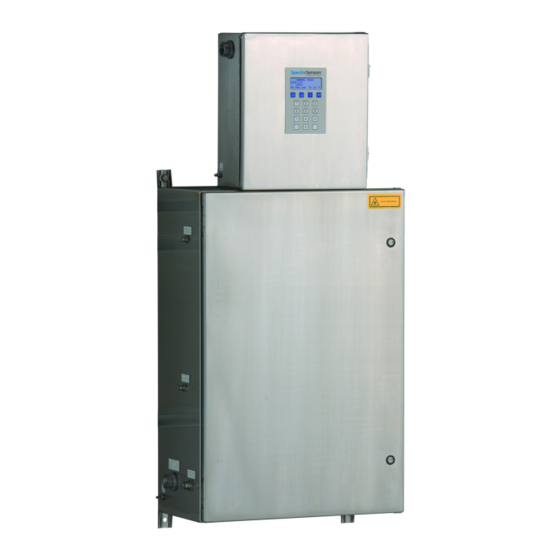
Endress+Hauser SpectraSensors SS500e Hardware Installation And Maintenance Manual (116 pages)
Gas Analyzer
Brand:
Endress+Hauser
| Category:
Measuring Instruments
| Size: 11.56 MB
Table of Contents
Table of Contents
5
Who Should Read this Manual
13
How to Use this Manual
13
General Warnings and Cautions
13
Instructional Symbols
15
Conventions Used in this Manual
15
Spectrasensors Overview
16
About the Gas Analyzers
16
Sample Conditioning System
16
Differences between the Ss500E, Ss2000E, and Ss3000E
16
How the Analyzers Work
17
Figure 1-1 Schematic of a Typical Laser Diode Absorption Spectrometer
17
Figure 1-2 Typical Raw Signal from a Laser Diode Absorption Spectrometer with and Without Mirror Contamination
18
Figure 1-3 Typical Normalized Absorption Signal from a Laser Diode Absorption Spectrometer
19
Wavelength Modulation Spectroscopy (WMS) Signal Detection
19
Getting Familiar with the Analyzer
20
Figure 1-5 Ss500E/Ss2000E Architecture Overview
21
Figure 1-6 Electronics Control Board (AC) for Single-Channel Systems (Ss500E/Ss2000E) with RS-232C to RS-485 Converter
22
Figure 1-7 Electronics Control Board (DC) for Single-Channel Systems (Ss500E/Ss2000E) with RS-232C to RS-485 Converter
23
Figure 1-8 Electronics Control Board (AC) for Dual-Channel Systems (Ss3000E) with RS-232C to RS-485 Converter
24
Figure 1-9 Electronics Control Board (DC) for Dual-Channel Systems (Ss3000E) with RS-232C to RS-485 Converter
25
Figure 1-10 Electronics Control Board (AC) for Dual-Channel Systems (Ss3000E) with RS-232C to Ethernet Converter
26
Figure 1-11 Electronics Control Board (DC) for Dual-Channel Systems (Ss3000E) with RS-232C to Ethernet Converter
27
Table 1-1 Fuse Specifications
28
Potential Risks Affecting Personnel
29
Mitigating Risks
29
Exposure to Process Gases
29
Exposure to Toxic Gas
29
Electrocution Hazard
30
Explosion Hazard
30
What Should be Included in the Shipping Box
31
Inspecting the Analyzer and SCS
31
Lifting/Carrying the Analyzer
31
Installing the Analyzer and SCS
32
Hardware and Tools for Installation
32
Figure 3-1 Analyzer Carrying Points/Methods
32
Hardware
33
Tools
33
Mounting the Analyzer
33
To Mount the Analyzer
33
Connecting Electrical Power to the Analyzer
34
Protective Chassis and Ground Connections
35
To Connect Electrical Power to the Analyzer
35
Connecting Electrical Power to the Enclosure Heater
38
To Connect Electrical Power to the Enclosure Heater
38
Figure 3-2 AC and DC Connection Terminal Blocks in Electronics Enclosure
38
Figure 3-3 AC Connection Terminal Block for Enclosure Heater
39
Application of Conduit Lubricant
40
Figure 3-4 Applying Conduit Lubricant
40
Connecting the Output Signals and Alarms
41
To Connect the Output Signals
41
Figure 3-5 Mating Terminal Block (TB2) in Electronics Enclosure for Connecting Signal Cables
42
Table 3-1 Output Signal Connections (RS-232C Configuration)
43
Table 3-2 Output Signal Connections (RS-485 Configuration)
43
Table 3-3 Output Signal Connections (Ethernet Configuration)
44
Configuring the Optional RS-232C/RS-485 Converter
44
Table 3-4 Output Signal Connections (Two-Wire RS-485 Configuration)
45
Figure 3-6 RJ-45 Connector
45
Configuring the Optional RS-232C/Ethernet Converter
45
Table 3-5 Standard Ethernet Cable RJ-45 Pin-Out
46
Table 3-6 Crossover Ethernet Cable RJ-45 Pin-Out
46
Changing the 4-20 Ma Current Loop Mode
47
To Change a 4-20 Ma Board from Source to Sink
47
Figure 3-7 4-20 Ma Output Board
47
To Scale the Current Loop Signal
48
Connecting the Gas Lines
49
To Connect the Sample Supply Line
49
To Connect the Sample Return
50
4: Sample Conditioning System
51
About the SCS
51
Typical SCS Component Overview
52
Sample Probe
52
Sample Regulators at the Probe
52
Sample Conditioning System Filters
53
Sample Regulator Heaters
53
Figure 4-1 Probe to Analyzer Interface
53
Sample Transport Tubing
54
Sample Bypass Flow Control
54
SCS Pressure Regulator
54
Sample Cell Flow Controller
54
Validation Systems
54
Sample Return/Vent
55
SCS Heaters
55
Checking the SCS Installation
55
To Perform SCS Installation Checks
55
Starting up the SCS
56
To Prepare for SCS Startup
56
To Start up the Field Pressure Reducing Station
57
To Start up the Sample Bypass Stream on Process Sample
57
To Start up the Analyzer on Process Sample
58
Shutting down the SCS
59
To Isolate the Measurement Sample Cell for Short-Term Shutdown
60
To Isolate the SCS for Short-Term Shutdown
60
To Isolate the Process Sample Tap for Long-Term Shutdown
61
5: Ethernet Serial Server
63
Software Installation
63
Configuration
63
Virtual COM Port Installation
64
Connecting to Ss500E/Ss2000E/Ss3000E Without Software Setup
64
Firewall Ports
65
Additional Information
65
Table 5-1 Ports to Open in Firewall
65
Appendix A: Specifications
67
Table A-1 Ss500E H O Analyzer Specifications
67
Table A-2 Ss2000E H 2 O Analyzer Specifications
68
Table A-5 Ss3000E H 2 O/CO 2 Analyzer Specifications
71
Figure A-1. Ss500E/Ss2000E Analyzer System Outline and Mounting
72
Figure A-2 Ss500E/Ss2000E Analyzer System Sample System Schematic
73
Figure A-3. Ss500E/Ss2000E Analyzer System Power and Signal Wiring
74
Figure A-4. Ss3000E Single Stream Analyzer System Outline and Mounting
75
Figure A-5. Ss3000E Single Stream Analyzer System Sample System
76
Figure A-6. Ss3000E Single Stream Analyzer System Power and Signal
77
Figure A-7. Ss3000E Dual Stream Analyzer System Outline and Mounting
78
Figure A-8. Ss3000E Dual Stream Analyzer System Sample System
79
Figure A-9. Ss3000E Dual Stream Analyzer System Sample System Schematic - Parts List (Sheet 2
80
Figure A-10 Ss3000E Dual Stream Analyzer System Power and Signal Wiring
81
Table A-6 Typical Natural Gas Stream Composition
82
Spare Parts
83
Table A-7 Replacement Parts for Ss500E/Ss2000E/Ss3000E O And/Or CO Analyzers
83
Appendix B: Troubleshooting & Maintenance
87
Gas Leaks
87
Contamination
87
To Keep the Sampling Lines Clean
88
Excessive Sampling Gas Temperatures and Pressures
88
Electrical Noise
89
Cleaning the Mirrors
89
Determining the Type of Cell Mirror
90
Figure B-1 Measurement Cell Types
90
To Clean the Mirror
91
Figure B-2 Stainless Steel Mirror Marking
91
To Replace the Stainless Steel Mirror
93
Figure B-3 Stainless Steel Mirror; Mirror Side up
94
Pressure Sensor Replacement
95
To Replace the Pressure Sensor
95
Figure B-4 Ss500E/Ss2000E SCS Cabinet Interior
96
Figure B-5 Removed Measurement Cell with Pressure Sensor Face up
97
Figure B-6 Removing the Old Pressure Sensor
97
Figure B-7 Removing Excess Seal Tape from Flange
98
Figure B-8 Replacing Seal Tape
98
Figure B-9 Replacing Pressure Sensor
99
Figure B-10 Newly Installed Pressure Sensor Positioning
99
Confirming the Relief Valve Setting
100
Replacing the Membrane Separators
101
Replacing the Filter
101
Peak Tracking Reset Procedure
102
Periodic SCS Maintenance
102
Regular SCS Status Check
103
To Check Filters
103
Instrument Problems
104
Table B-1 Potential Instrument Problems and Solutions
104
Service Contact
109
Before Contacting Technical Service
109
Service Repair Order
109
Renewity
109
Packing
110
To Purge the Analyzer for Shipment/Relocation
110
To Prepare the Analyzer for Shipment or Storage
110
Storage
111
Disclaimers
111
Warranty
111
Advertisement
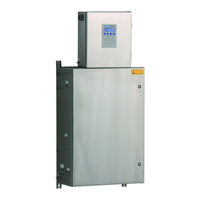
Endress+Hauser SpectraSensors SS500e Operator's Manual (114 pages)
Brand:
Endress+Hauser
| Category:
Measuring Instruments
| Size: 3.52 MB
Table of Contents
Table of Contents
5
List of Figures
9
List of Tables
11
Who Should Read this Manual
13
General Informational Icons
13
Conventions Used in this Manual
14
Spectrasensors Overview
14
Manufacturer Address
14
Firmware Version
15
Powering up the Analyzer
15
To Power up the Analyzer
15
Powering down the Analyzer
16
To Power down the Analyzer
17
Operating the Analyzer from the Keypad
17
Modes Defined
19
Mode 1: (Normal Mode)
19
Mode 2: (Set Parameter Mode)
19
Mode 3: Not Used
20
Mode 4: (System Diagnostic Parameters)
20
Mode 5: (4-20 Ma Test Mode)
20
Mode 6: (Diagnostic Data Download)
21
Mode 7: (Measure Port1 Mode)
21
Mode 8: (Measure Port2 Mode)
22
Mode 9: (Recall Validation Results)
22
Mode Test: (Analog Input Test Mode)
24
Configuring the Analyzer at Start-Up
24
Parameter Setting/Checking Procedure
24
Changing Measurement and Control Parameters
25
Table 2-1 Typical Values for Parameter Setpoints
25
To Change Parameters in Mode 2
29
Measurement and Control Parameters Defined
29
Way Com Port
30
4-20 Ma Alarm Action
30
4-20 Ma Val Action
30
AI 4 Ma Value
31
AI 20 Ma Value
31
AI Pressure Input
31
AO 4 Ma Value
31
AO 4-20 Ma Test
32
AO 20 Ma Value
32
Baud Rate
32
Calculate Dew Point
33
Cancel Val Alarms
33
Concentration Unit
33
Table 2-2 Default Conversion Factors
34
Custom Precision
35
Daily Validation
35
Dew Point Method
35
DO Alarm Setup
36
Table 2-3 Assignable Alarm Functionality
36
General Alarm DO
38
High Alarm Setpoint
38
Keypad Watchdog
38
Logger Rate
39
Low Alarm Setpoint
39
Modbus Address
39
Modbus Mode
39
Operator Parameter01 to Operator Parameter20
40
To Access the Operator Parameter Section
40
Peak Tracking
42
Pipeline Pressure
42
Pressure Unit
42
RATA (Relative Accuracy Test Audit)
43
RATA Multiplier
43
RATA Offset
43
Set Time - Day
43
Set Time - Hour
44
Set Time - Minute
44
Set Time - Month
44
Set Time - Year
44
Start Validation
45
Temperature Unit
45
Update RATA
45
Val 1 Concentration
46
Val 2 Concentration
46
Val Attempts
46
Val Auto Dumpspectrm
47
Validation Allowance
47
Validation Wait Time
47
Val Interval
48
Val Perm Constant Kp
48
Val Perm Rate Rp
48
Val Start Time
49
Zero Val Tolerance
49
Adjusting Analyzer Reading to Match Specific Standard(S)
49
To Adjust the Analyzer Reading
51
Application Examples
52
To Set Manual Dual Validation
52
To Set Semi-Automatic Single or Dual Validation
52
Automatic Single or Dual Validation
53
Validating the Analyzer
54
To Validate Automatically
54
To Validate Semi-Automatically
54
To Validate Manually
54
Scaling and Calibrating the Current Loop Signal
55
To Scale the Current Loop Signal
55
Warnings
56
Alarms
56
System Faults
56
User Alarms
57
Assignable Alarm
58
Validating the Analyzer
58
To Validate Automatically
58
To Validate Semi-Automatically
58
To Validate Manually
58
Calibrating the Analyzer
59
Switching Stream Compositions
59
To Measure Stream 1
59
To Measure Stream 2
60
3: Serial Port Communications
61
Receiving Serial Data (Customer Port Output)
61
To Launch Hyperterminal
61
Mode 1 Data String
61
To Capture and Save Data from the Serial Port
65
To Read Diagnostic Data with Hyperterminal
65
Mode 6 Data
66
Viewing Diagnostic Data with Microsoft Excel
68
To Import the Data File into Excel
68
Modbus Communications Protocol
72
Framing/Protocol
72
Functions
72
Reading/Writing in Daniel Modbus Mode
72
Reading/Writing in Gould Modbus Mode
72
Endianness
73
To Enable Modbus Communications
73
Addressing
74
Table 3-1 Modbus Register Map
75
Modbus Accessible Parameter Definitions
80
Table 3-2 Assignable Alarm Functionality
80
Table 3-3 Status Flags
87
Table 3-4 ASCII Character Map
88
4: Ethernet Communications
91
Configuring the Built-In Ethernet Port
91
To Configure the Built-In Ethernet Port with Telnet
91
To Configure the Built-In Ethernet Port with the Web Manager
92
Network Mode
95
Automatic IP Address Configuration
95
To Assign an IP Address Automatically
95
Static IP Address Configuration
95
To Assign an IP Address Manually
96
Ethernet Configuration
96
To Specify How Data will be Transmitted
96
Channel Connection
97
To Configure a Channel's TCP Settings
97
General Information for Configuring Ethernet
99
Appendix A: Troubleshooting
101
Contamination
101
Excessive Sampling Gas Temperatures and Pressures
101
Peak Tracking Reset Procedure
101
To Reset the Peak Tracking Function
102
Instrument Problems
103
Table A-1 Potential Instrument Problems and Their Solutions
103
Service Contact
104
Before Contacting Service
105
Disclaimers
105
Index
107
Endress+Hauser SpectraSensors SS500e Hardware Installation And Maintenance Manual (121 pages)
Brand:
Endress+Hauser
| Category:
Measuring Instruments
| Size: 13.92 MB
Table of Contents
Table of Contents
5
List of Figures
9
List of Tables
11
1 : Introduction
13
Who Should Read this Manual
13
How to Use this Manual
13
Conventions Used in this Manual
13
General Warnings and Cautions
13
Safety Warning Label
14
Equipment Labels
15
Instructional Symbols
16
Spectrasensors Overview
16
Manufacturer Address
16
About the Gas Analyzers
17
Determining the Analyzer Firmware Version
17
Sample Conditioning System
17
How the Analyzers Work
17
Differential TDLAS
20
Wavelength Modulation Spectroscopy (WMS) Signal Detection
20
Getting to Know the Analyzer
21
Fuses
27
Table 1-1 Fuse Specifications (Analyzer A)
27
Table 1-2 Fuse Specifications (Analyzer B)
28
2 : Safety
29
Potential Risks Affecting Personnel
29
Mitigating Risks
29
Exposure to Process Gases
29
Exposure to Toxic Gas
29
Electrocution Hazard
30
Explosion Hazard
30
3 : Installation
31
What Should be Included in the Shipping Box
31
Lifting/Carrying the Analyzer
31
Inspecting the Analyzer
32
Mounting and Installing the Analyzer
33
Hardware and Tools for Mounting and Installation
33
Hardware
33
Tools
33
To Mount the Analyzer
34
Connecting Electrical Power to the Analyzer
34
Protective Chassis and Ground Connections
35
To Connect Electrical Power to Analyzer a
36
Field Interface Loads (Solenoid Valves)
39
Connecting Electrical Power to the SCS Enclosure Heater
39
To Connect Electrical Power to the Enclosure Heater
39
Application of Conduit Lubricant
40
Connecting the Output Signals and Alarms
41
To Connect Analyzer a Signal and Alarm Cables
42
To Connect the Analyzer B Signal and Alarm Cables
44
Table 3-1 Analyzer a Input/Output Signal Connections
44
Changing the 4-20 Ma Current Loop Mode
46
Table 3-2 Analyzer B Input/Output Signal Connections
46
To Change 4-20 Ma Board from Source to Sink (Analyzer a or B)
47
To Calibrate the Analog Output (Analyzer A)
48
To Calibrate the Analog Output (Analyzer B)
48
Ethernet Connection (Optional)
49
To Test and Adjust 4-20 Ma Zero and Span (Analyzer a or B)
49
Connecting the Gas Lines
49
To Connect the Sample Supply Lines
50
To Connect the Sample Returns
51
To Connect the Pneumatic Valve Source (if Applicable)
52
Connecting the Validation Gas Source (if Applicable)
52
To Connect the Validation Source
52
Conditioning the SCS Tubing
53
Heat Trace Bundle Sleeve (Optional)
53
To Install the Heated Line Seal
54
Tools Needed
54
Installing the Heat Trace Bundle
54
4 : Sample Conditioning System
55
About the SCS
55
Checking the SCS Installation
56
To Perform SCS Installation Checks
56
Starting up the SCS
58
To Prepare for SCS Startup
58
To Start up the Sample System Heater
58
To Start up the Field Pressure Reducing Station
59
To Start up the Sample Bypass Stream on Process Sample
60
To Start up the Analyzer on Process Sample
60
Shutting down the SCS
61
To Isolate the Measurement Cell for Short-Term Shutdown
62
To Isolate the SCS for Short-Term Shutdown
62
To Isolate the Process Sample Tap for Long-Term Shutdown
63
To Purge for Shipment/Relocation
65
Heat Trace Bundle Sleeve (Optional)
65
Removing the Heat Trace Bundle
65
Appendix A: Specifications
67
Spare Parts
80
Table A-3 Replacement Parts for 2-Pack Analyzer
80
Appendix B: Maintenance and Troubleshooting
85
Gas Leaks
85
Contamination
85
Excessive Sampling Gas Temperatures and Pressures
86
Electrical Noise
86
Peak Tracking Reset Procedure
86
Relief Valve Setting
87
Cleaning the Sampling Lines
87
To Keep the Sampling Lines Clean
87
Cleaning the Mirrors
87
Tools and Supplies
88
Determining the Type of Cell Mirror
88
To Clean the Mirrors
90
To Replace the Stainless Steel Mirror
92
Pressure Sensor Replacement
93
To Replace the Pressure Sensor on a 8 M or 28 M Cell
93
Tools and Materials
93
To Replace the Pressure Sensor on a 0.8 M or 0.1 M Cell
99
Tools and Materials
99
Periodic SCS Maintenance
103
Preventive and On-Demand SCS Maintenance
104
SCS Status Check
105
To Check the Filter
105
To Replace the Filter
106
Servicing the H S Scrubber
106
To Replace the Scrubber and Scrubber Efficiency Indicator
108
Disposal of Used Scrubbers
110
Instrument Issues
110
Table B-1 Potential Analyzer Issues and Solutions
110
Packing
114
To Prepare the Analyzer for Shipment or Storage
114
Storage
115
Service Contact
115
Before Contacting Service
115
Service Repair Order
116
Renewity Returns
116
Disclaimers
116
Warranty
116
Index
117
Advertisement
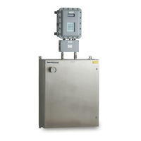
Endress+Hauser SpectraSensors SS500e Operating Instruction (98 pages)
H2S TDLAS Gas Analyzer
Brand:
Endress+Hauser
| Category:
Measuring Instruments
| Size: 7.71 MB
Table of Contents
Table of Contents
3
Who Should Read this Manual
5
How to Use this Manual
5
General Warnings and Cautions
5
Conventions Used in this Manual
5
Safety Warning Label
6
Equipment Labels
7
Instructional Symbols
8
Manufacturer Address
8
About the Gas Analyzers
8
Sample Conditioning System
9
Determining Firmware Version
9
How the Analyzers Work
9
Differential TDLAS
12
Wavelength Modulation Spectroscopy (WMS) Signal Detection
12
Getting Familiar with the Gas Analyzer
13
Potential Risks Affecting Personnel
17
Mitigating Risks
17
Explosion Hazard
18
What Should be Included in the Shipping Box
19
Inspecting the Analyzer and SCS
19
Installing the Analyzer
20
Hardware and Tools for Installation
20
Hardware
20
Tools
20
Mounting the Analyzer
21
Lifting/Carrying the Analyzer
21
Connecting Electrical Power to the Analyzer
22
Protective Chassis and Ground Connections
23
Field Interface Loads (Solenoid Valves)
26
Connecting Electrical Power to the Enclosure Heater
26
Connecting the Output Signals and Alarms
28
Changing the 4-20 Ma Current Loop Mode
31
Connecting the Gas Lines
33
Instrument Air
34
Conditioning the SCS Tubing
36
Heat Trace Bundle Sleeve (Optional)
36
Tools
37
4: Sample Conditioning System
39
About the SCS
39
Checking the SCS Installation
40
Starting up the SCS
42
Shutting down the SCS
45
Heat Trace Bundle Sleeve (Optional)
49
Appendix A: Specifications
51
Spare Parts
62
Appendix B: Maintenance and Troubleshooting
65
Gas Leaks
65
Contamination
65
Excessive Sampling Gas Temperatures and Pressures
66
Electrical Noise
67
Relief Valve Setting
67
Peak Tracking Reset Procedure
67
Cleaning the Mirrors
67
Tools and Supplies
68
Replacing the Pressure Sensor
72
Tools and Materials
73
Periodic SCS Maintenance
78
Preventive and On-Demand SCS Maintenance
79
Servicing the H S Scrubber
80
Instrument Troubleshooting
84
Service
89
Service Repair Order
89
Renewity Returns
89
Before Contacting Service
89
Packing
89
Storage
91
Disclaimers
91
Warranty
91
Index
93
Advertisement
Related Products
Endress+Hauser SS500
Endress+Hauser SS500XP
Endress+Hauser SpectraSensors SS2100r
Endress+Hauser SpectraSensors SS2100
Endress+Hauser SS2100a
Endress+Hauser SS2100i-2
Endress+Hauser SS2000
Endress+Hauser SS2000XP
Endress+Hauser SS3000
Endress+Hauser SS2100 Series
Endress+Hauser Categories
Measuring Instruments
Transmitter
Radar
Switch
Accessories
More Endress+Hauser Manuals
Login
Sign In
OR
Sign in with Facebook
Sign in with Google
Upload manual
Upload from disk
Upload from URL