Endress+Hauser SS2100i-1 Operating Instructions Manual
Tdlas gas analyzer, atex/iecex/ukex: zone 1
Hide thumbs
Also See for SS2100i-1:
- Hardware installation and maintenance manual (122 pages) ,
- Overview manual (47 pages) ,
- Safety manual (36 pages)

Related Manuals for Endress+Hauser SS2100i-1


Summary of Contents for Endress+Hauser SS2100i-1
- Page 1 BA02189C/66/EN/02.23 Products Solutions Services 70207462 Operating Instructions SS2100i-1 TDLAS Gas Analyzer ATEX/IECEx/UKEX: Zone 1...
- Page 2 Operating Instructions SS2100i-1 TDLAS Gas Analyzer Endress+Hauser...
-
Page 3: Table Of Contents
6.4 Contamination ............34 2.6 Differential TDLAS ..........9 6.5 Cleaning the mirrors ..........35 2.7 Getting familiar with the SS2100i-1 ....10 6.6 Pressure sensor replacement ....... 41 Safety ........... 18 6.7 Flame arrestor replacement and safety ..... 45 3.1 Potential risks affecting personnel ..... -
Page 4: About This Document
European economic area (EEA). Table 2. Symbols U.S. export compliance The policy of Endress+Hauser is in strict compliance with U.S. export control laws as detailed in the website of the Bureau of Industry and Security at the U.S. Department of Commerce. -
Page 5: Introduction
General warnings and cautions Instructional icons are provided in this manual and on the SS2100i-1 unit to alert the user of potential hazards, important information, and valuable tips. Following are the symbols and associated warning and caution types to observe when servicing the analyzer. - Page 6 Flammable. Gases used in the processing of this analyzer may be extremely flammable. Any work in a hazardous area must be carefully controlled to avoid creating any possible ignition sources (e.g., heat, arcing, sparking, etc.). Toxins. Endress+Hauser analyzers measure a variety of gases, including high-level H S. Follow all safety protocols governing toxic gases and potential leaks.
-
Page 7: Manufacturer Address
About the gas analyzers The SS2100i-1 analyzers are tunable diode laser (TDL) absorption spectrometers operating in the near- to short- wavelength infrared. Each compact sensor consists of a TDL light source, sample cell, and detector specifically configured to enable high sensitivity measurement of a particular component within the presences of other gas phase constituents in the stream. -
Page 8: How The Analyzers Work
With the SS2100i-1 analyzers, sample gas flows continuously through the sample cell ensuring that the sample is always representative of the flow in the main pipe. -
Page 9: Differential Tdlas
2.6.1 Wavelength modulation spectroscopy (WMS) signal detection Endress+Hauser takes the fundamental absorption spectroscopy concept a step further by using a sophisticated signal detection technique called wavelength modulation spectroscopy (WMS). When employing WMS, the laser drive current is modulated with a kHz sine wave as the laser is rapidly tuned. A lock-in amplifier is then used to detect the harmonic component of the signal that is at twice the modulation frequency (2f), as shown in Figure 5. -
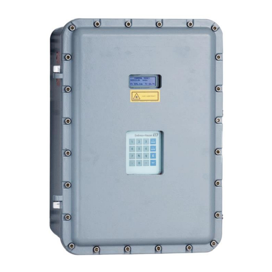
Page 10: Getting Familiar With The Ss2100I-1
700 to 3000 nm, which provides the least amount of sensitivity to background stream variations. Getting familiar with the SS2100i-1 The SS2100i-1 consists of a single enclosure containing two electrical assembly panels. Figure 6 shows the front, rear, and bottom of the analyzer. Figure 6. External features of the analyzer ... - Page 11 SS2100i-1 TDLAS Gas Analyzer Operating Instructions Figure 7. Upper and lower levels of analyzer assembly (8/28 m sample cell) Figure 8. Upper and lower levels of analyzer assembly (0.8 m sample cell) Endress+Hauser...
- Page 12 Operating Instructions SS2100i-1 TDLAS Gas Analyzer Figure 9. Upper and lower levels of analyzer assembly (0.1 m sample cell) Figure 10. Components on electronics panel assembly (upper level) Endress+Hauser...
- Page 13 SS2100i-1 TDLAS Gas Analyzer Operating Instructions Figure 11. Components on sample cell panel assembly (8/28 m sample cell) (lower level) Figure 12. Components on sample cell panel assembly (0.8 m sample cell) (lower level) Endress+Hauser...
- Page 14 Operating Instructions SS2100i-1 TDLAS Gas Analyzer Figure 13. Components on sample cell panel assembly (0.1 m sample cell) (lower level) On the upper level (electronics panel assembly), the analyzer power supply provides power to the analyzer control electronics and relays controlling valves. The analyzer control electronics drive the laser, collect the signal and analyze the spectra.
- Page 15 SS2100i-1 TDLAS Gas Analyzer Operating Instructions Drawing Reference Description Rating Miniature fuse, 5 x 20 mm, time delay 250 VAC/1.6 A Miniature fuse, 5 x 20 mm, time delay 250 VAC/0.5 A , F6 , F7 , F8 Miniature fuse, 5 x 20 mm, time delay 250 VAC/0.1 A...
- Page 16 Operating Instructions SS2100i-1 TDLAS Gas Analyzer Figure 15. Label placement on electronics panel assembly (upper level) Figure 16. Label placement on sample cell panel assembly (8/28 m sample cell) (lower level) Endress+Hauser...
- Page 17 SS2100i-1 TDLAS Gas Analyzer Operating Instructions Figure 17. Label placement on sample cell panel assembly (0.8 m sample cell) (lower level) Figure 18. Label placement on sample cell panel assembly (0.1 m sample cell) (lower level) Endress+Hauser...
-
Page 18: Safety
Operating Instructions SS2100i-1 TDLAS Gas Analyzer Safety Potential risks affecting personnel This section addresses the appropriate actions to undertake when faced with hazardous situations during or before service of the analyzer. It is not possible to list all potential hazards within this document. The user is responsible for identifying and mitigating any potential hazards present when servicing the analyzer. -
Page 19: Installation
4.3.1 Hardware • Mounting hardware used for wall-mounting the SS2100i-1 must be able to support four times the weight of the instrument (86 kg [190 lbs.]) not including the sample system) • Stainless steel tubing using 6.35 mm (0.25 in.) O.D. x 0.889 mm (0.035 in.) wall thickness, seamless 316L stainless steel electropolish tubing is recommended) •... -
Page 20: Mounting The Analyzer
Before removing the crate, move the analyzer crate as close as possible to the final location. Due to the analyzer’s weight (approximately 86 Kg [190 lbs]), Endress+Hauser recommends the use of a forklift, pallet jack, etc. to lift and/or move the analyzer. If the analyzer is to be lifted by hand, designate multiple individuals to lift by the mounting brackets, and distribute the weight among personnel to avoid injury. -
Page 21: Connecting The Solenoid Valves
SS2100i-1 TDLAS Gas Analyzer Operating Instructions Connecting the solenoid valves Solenoid valves are used on differential analyzer systems only, not on non-differential systems. Contact Service for any questions or clarifications. Refer to to Service → Differential systems require solenoid valves to switch between process flow and flow that has been scrubbed of the analyte. - Page 22 Operating Instructions SS2100i-1 TDLAS Gas Analyzer Figure 20. Preferred basic differential system with one solenoid valve driving two pneumatic valves Figure 21. Differential system with single autovalidation requiring two solenoid valves driving three pneumatic valves Endress+Hauser...
- Page 23 SS2100i-1 TDLAS Gas Analyzer Operating Instructions Figure 22. Differential system with dual autovalidation requiring four solenoid valves driving eight pneumatic valves Certified glands and cables should be used where appropriate in compliance with local regulations Hazardous voltage and risk of electric shock.
- Page 24 Operating Instructions SS2100i-1 TDLAS Gas Analyzer 4.6.1 To connect the solenoid valves 1. Open the analyzer enclosure cover according to the procedure in section 4.5.1 → to gain access to the field interface terminal block. 2. Using a compound barrier seal gland (assembled per manufacturer instructions), screw the gland into the M25 access port on the bottom left of the enclosure.
-
Page 25: Connecting Electrical Power To The Analyzer
Certified compound barrier seal glands shall be used; cables used shall comply with electrical code, standards, suitable for the glands and meet the local regulations. Use copper conductors only. The electrical power and the signal wiring for the SS2100i-1 analyzer is connected through the conduit hub at the bottom of the electronics enclosure. 4.7.1 Protective chassis and ground connections Before connecting any electrical signal or power, the protective and chassis grounds must be connected. - Page 26 Operating Instructions SS2100i-1 TDLAS Gas Analyzer Because the breaker in the power distribution panel or switch will be the primary means of disconnecting the power from the analyzer, the power distribution panel or switch should be located in close proximity to the equipment and within easy reach of the operator.
-
Page 27: Connecting The Signals And Alarms
4.7.3 Application of gland lubricant To ensure proper installation, Endress+Hauser recommends using STL8 screw thread lubricant or equivalent on all screw thread and its tapped opening. STL8 Screw Thread Lubricant is a lithium based, anti-galling substance with excellent adhesion that maintains rain- tightness and grounding continuity between gland fittings. - Page 28 Operating Instructions SS2100i-1 TDLAS Gas Analyzer 2. Install compound barrier seal glands into the three M25 access ports on the bottom right of the enclosure. Refer section 4.7.3 → 3. Pull the cables for the alarm outputs and validation request input through the first (from left) gland, the cables for the 4-20 mA AI and 4-20 mA AO through the second gland and the cable for serial or Ethernet communication through the third gland and into the enclosure.
-
Page 29: Configuring The Rs-232/Rs-485 Converter
All work should be performed by technicians qualified in pneumatic tubing. Endress+Hauser recommends using 6.35 mm (0.25 in.) O.D. x 0.889 mm (0.035 in.) wall thickness, seamless stainless steel tubing. If the analyzer includes a factory installed sample system, see the system drawings for tubing sizes and attachment points. -
Page 30: Changing The 4-20 Ma Current Loop Mode
Operating Instructions SS2100i-1 TDLAS Gas Analyzer 4.10.1 To connect the sample supply and return lines 1. Connect the supply and return tubes to the analyzer using the stainless steel compression-type fittings provided. 2. Tighten all new fittings 1-1/4 turns with a wrench from finger tight. For connections with previously swaged ferrules, thread the nut to the previously pulled up position, then tighten slightly with a wrench. -
Page 31: Appendix A: Specifications
SS2100i-1 TDLAS Gas Analyzer Operating Instructions Appendix A: Specifications SS2100i-1 analyzer specifications 5.1.1 Performance Name Description Concentration See analyzer calibration report Repeatability See analyzer calibration report Measurement time Typically less than 20 seconds Table 13. Performance 5.1.2 Application data Name... -
Page 32: Exd Accessory Conditions Of Use
Operating Instructions SS2100i-1 TDLAS Gas Analyzer 5.1.4 Physical specifications Name Description IP66 copper-free aluminum with marine environment RAL 7001 gray polyurethane enamel finish; Electronics enclosure approximately 300 mm final thickness Analyzer dimensions 670 mm H x 580 mm W x 377 mm D (26.3 in. - Page 33 SS2100i-1 TDLAS Gas Analyzer Operating Instructions 5.2.1 Outline and mounting diagram Figure 28. Outline and mounting diagram Endress+Hauser...
-
Page 34: Appendix B: Maintenance And Troubleshooting
Operating Instructions SS2100i-1 TDLAS Gas Analyzer Appendix B: Maintenance and troubleshooting INVISIBLE LASER RADIATION — Avoid exposure to beam. Class 3b Radiation Product. Refer servicing to the manufacturer-qualified personnel. The optical head has a seal and “WARNING” sticker to prevent inadvertent tampering with the device. Do not attempt to compromise the seal of the optical head assembly. -
Page 35: Cleaning The Mirrors
If contamination makes its way into the cell and accumulates on the internal optics, a Laser Power Low Alarm fault will result. Cleaning the mirrors Contact Service if mirror contamination is suspected in your SS2100i-1 analyzer. Refer to to Service → . If advised to do so, use the following procedure. - Page 36 Operating Instructions SS2100i-1 TDLAS Gas Analyzer 6.5.2 To determine the type of mirror being used for the system cell Before determining whether to clean or replace the mirror, identify the type of measurement cell being used in the analyzer. There are four types of measurement cells; 0.1 m, 0.8 m, 8 m, and 28 m. Refer to Figure 29 below.
- Page 37 SS2100i-1 TDLAS Gas Analyzer Operating Instructions Process samples may contain hazardous material in potentially flammable and/or toxic concentrations. Personnel should have a thorough knowledge and understanding of the physical properties of the sample and prescribed safety precautions before operating the analyzer.
- Page 38 To remove the cell and mirror assembly (28 m/8 m) Only the 28 m and 8 m cells need to be removed from the system to accommodate mirror cleaning. Endress+Hauser recommends having two individuals available to perform this part of the procedure. ...
- Page 39 Endress+Hauser recommends having two individuals available to perform this part of the procedure. 1. While supporting the electronics assembly panel, carefully mark the orientation of the mirror assembly on the cell body using a permanent ink marker.
- Page 40 1. For the 28 m and 8 m cells, look inside the sample cell at the top mirror using a flashlight to ensure that there is no contamination on the top mirror. For 0.8 m and 0.1 m cells, proceed to the step 3. Endress+Hauser does not recommend cleaning the top mirror. Refer to to Service → if the top mirror is visibly contaminated.
-
Page 41: Pressure Sensor Replacement
SS2100i-1 TDLAS Gas Analyzer Operating Instructions 4. Check the O-Ring. If a new O-Ring is needed, apply grease on fingertips and then to the new O-Ring. Place newly greased O-Ring into the groove around the outside of the mirror taking care not to touch the mirror surface. - Page 42 Operating Instructions SS2100i-1 TDLAS Gas Analyzer 6.6.2 To replace the pressure sensor Use the following instruction to replace a pressure sensor. 1. Close the external flow of gas to the sample conditioning system (SCS) at the sample inlet. 2. Purge the system by connecting dry nitrogen to the sample inlet. Allow the SCS to purge for 5 to 10 minutes.
- Page 43 SS2100i-1 TDLAS Gas Analyzer Operating Instructions 7. Remove the black wire harness cap from the sensor as shown in Figure 37 below. Figure 37. Removing the harness cap The harness cap will remain connected to the pressure sensor cable via the terminal block on the upper level panel.
- Page 44 Operating Instructions SS2100i-1 TDLAS Gas Analyzer 14. Insert the new pressure sensor onto the ‘T’ junction. 15. Hand tighten the pressure sensor clockwise on the ‘T’ junction until it is no longer moving freely. 16. Turn the sensor clockwise with a 7/8 in. or adjustable wrench until tight. Two or three threads on the pressure sensor should still be visible.
-
Page 45: Flame Arrestor Replacement And Safety
SS2100i-1 TDLAS Gas Analyzer Operating Instructions Flame arrestor replacement and safety The analyzer system comes equipped with a protective covering over the flame arrestors and tubing that runs from the analyzer electronics to the SCS. Refer to the analyzer system drawings to locate the protective enclosure for your analyzer;... - Page 46 Operating Instructions SS2100i-1 TDLAS Gas Analyzer 5. Disassemble the tubing using a 9/16 in. wrench. Refer to Figure 42 below. Figure 42. Flame arrestor positions inside enclosure 6. Remove the flame arrestor using a 7/8 in. wrench. Refer to Figure 43 below.
-
Page 47: Potential Health Effects
SS2100i-1 TDLAS Gas Analyzer Operating Instructions Potential health effects The flame arrestor enclosure is packed with insulation material that can cause health issues if inhaled, exposed to bare skin or in direct contact with eyes. Please follow the safety procedures for unpacking this enclosure to access the flame arrestors and review the following potential health effects of the insulation material before beginning maintenance on the flame arrestors. -
Page 48: Peak Tracking Reset Procedure
Operating Instructions SS2100i-1 TDLAS Gas Analyzer Peak tracking reset procedure The analyzer’s software is equipped with a peak tracking function that keeps the laser scan centered on the absorption peak. Under some circumstances, the peak tracking function can get lost and lock onto the wrong peak. If the PeakTk Restart Alarm is displayed, the peak tracking function should be reset. - Page 49 SS2100i-1 TDLAS Gas Analyzer Operating Instructions Symptom Response Strange characters appear on front Check connections on the display communication cable. panel display Pressing keys on front panel do not have Check connections on the keypad cable. specified effect Not getting enough flow to the sample Check both the micro filter and membrane separator for contamination.
-
Page 50: Service
6.12 Packing, shipping, and storage Endress+Hauser’s TDLAS Analyzer Systems and auxiliary equipment are shipped from the factory in appropriate packaging. Depending on the size and weight, the packaging may consist of a cardboard-skinned container or a wooden palletized crate. All inlets and vents are capped and protected when packaged for shipment. The system should be packed in the original packaging when shipped or stored for any length of time. -
Page 51: Storage
Warranty For a period of 18 months from date of shipment or 12 months in operation, whichever comes first, Endress+Hauser warrants that all products sold by it shall be free from defects in material and workmanship under normal use and service when correctly installed and maintained. -
Page 52: Appendix C: Analyzer Parts
SS2100i-1 TDLAS Gas Analyzer Appendix C: Analyzer parts This chapter provides lists and illustrations of all field replaceable parts used in the SS2100i-1 analyzer. Due to a policy of continuous improvement, parts, and part numbers may change without notice. Not all parts listed are included on every analyzer. When ordering, please specify the system serial number (S/N) to ensure that the correct parts are identified. - Page 53 SS2100i-1 TDLAS Gas Analyzer Operating Instructions Figure 45. Electronics panel assembly parts (continued) Figure 46. Electronics panel assembly parts (continued) Endress+Hauser...
- Page 54 Operating Instructions SS2100i-1 TDLAS Gas Analyzer Figure Number Reference Number Part Number Description Figure 47 2100002087 Terminal Block, Double Deck, Gray 2100002085 Terminal Block, Ground 4500002015 Circuit Breaker, 9926 Series 2100002086 Terminal Block Fuse, UK 5-HESILA 250, Un-500 V, In-6.3 A 4500002010 Fuse, miniature, 5 x 20 mm, 0.5 A...
- Page 55 SS2100i-1 TDLAS Gas Analyzer Operating Instructions Figure Number Reference Number Part Number Description Figure 48 2800002063 Relay, 861 Solid State with Internal Heat Sink 4000002038 Temperature Controller: Watlow EZ-Zone RM Rail Mount EX5300000001 Heater, 230 VAC, 200 W, EExd IIC T3...
- Page 56 Operating Instructions SS2100i-1 TDLAS Gas Analyzer Figure Number Reference Number Part Number Description Figure 50 2800002063 Relay, 861 Solid State with Internal Heat Sink 4000002038 Temperature Controller: Watlow EZ-Zone RM Rail Mount EX5300000001 Heater, 230 VAC, 200 W, EExd IIC T3...
- Page 57 SS2100i-1 TDLAS Gas Analyzer Operating Instructions Figure Number Reference Number Part Number Description Figure 51 EX5300000001 Heater, 230 VAC, 200 WM EExd IIC T3 4500002014 Thermostat, Manual Reset, 2455RM 2400002105 Terminal Block, 4 Position, G 5/4 2100002107 Terminal Block, Type MT 1, 5, Phoenix...
- Page 58 Operating Instructions SS2100i-1 TDLAS Gas Analyzer Figure Number Reference Number Part Number Description Figure 53 2400002161 Display, LCD, 20X4, Backlit, 5 V, Serial 2400002157 Keypad, Touch Sensitive, 16KEYS EX1300000026 Flame Arrestor, 1/2 NPT x 1/4 NPT, SS, EExd EX1300000009 Flameproof Breather/Drainer, M20, Exd, ATEX/IECEx Table 27.
- Page 59 Washer, Sealing, SS, M10 1300002425 Screw, Socket Head Cap, 304SS, M10x35 1300002426 Screw, Socket Head Cap, 304SS, M10x30 1100002209 Kit, SS2100i-1, M10x35 Bolts and M10 Washer 0219900007 Kit, Cleaning Tools, Optical Cell (USA/Canada) 0219900017 Kit, Cleaning Tools, Optical Cell (International) 1100002156...
-
Page 60: Appendix D: Wiring Diagrams
Operating Instructions SS2100i-1 TDLAS Gas Analyzer Appendix D: Wiring diagrams Figure 54. Wiring schematic of SS2100i-1 electronics power systems Figure 55. Wiring schematic of SS2100i-1 heater system Endress+Hauser... - Page 61 SS2100i-1 TDLAS Gas Analyzer Operating Instructions Figure 56. Wiring schematic of SS2100i-1 digital I/O Figure 57. Wiring schematic of SS2100i-1 alarms Endress+Hauser...
- Page 62 Operating Instructions SS2100i-1 TDLAS Gas Analyzer Figure 58. Wiring schematic of SS2100i-1 serial and Ethernet signals Figure 59. Wiring schematic of SS2100i-1 inter-card connections Endress+Hauser...
- Page 63 SS2100i-1 TDLAS Gas Analyzer Operating Instructions Figure 60. Wiring schematic of SS2100i-1 sample cell connections Figure 61. Wiring schematic of SS2100i-1 sample cell connections (continued) Endress+Hauser...
- Page 64 Operating Instructions SS2100i-1 TDLAS Gas Analyzer www.addresses.endress.com Endress+Hauser...