Endress+Hauser SpectraSensors SS500 Hardware Installation And Maintenance Manual
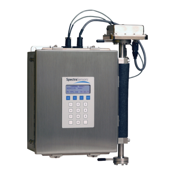
Single channel gas analyzer
Hide thumbs
Also See for SpectraSensors SS500:
- Safety instruction (52 pages) ,
- Hardware installation and maintenance manual (121 pages) ,
- Operator's manual (114 pages)

Related Manuals for Endress+Hauser SpectraSensors SS500


Summary of Contents for Endress+Hauser SpectraSensors SS500
- Page 1 SS500/SS2000 Single Channel Gas Analyzer Hardware Installation and Maintenance Manual P/N 4900002285 rev B...
- Page 3 SS500/SS2000 Single Channel Gas Analyzer Hardware Installation and Maintenance Manual Use this manual with the Firmware Operator’s Manual Products of 4333 W Sam Houston Pkwy N, Suite 100 Houston, TX 77043-1223 Tel: 800.619.2861 Fax: 713.856.6623 www.spectrasensors.com Copyright © 2020 SpectraSensors, Inc. No part of this manual may be reproduced in whole or in part without the express written permission of SpectraSensors, Inc.
- Page 4 Revision History Revision Engineering Order Date EO17516 June 7, 2018 ECR18150 March 26, 2020...
-
Page 5: Table Of Contents
ABLE OF ONTENTS 1: Introduction Who Should Read This Manual ........1-1 How to Use This Manual. - Page 6 SS500/SS2000 Analyzer Starting up the full-featured sample system ......4-5 To start up the sample bypass stream on process sample ....4-6 To start up the analyzer on process sample .
- Page 7 IST OF IGURES Figure 1–1. Schematic of typical tunable diode laser absorption spectrometer ........1-5 Figure 1–2.
- Page 8 SS500/SS2000 Analyzer Figure B–1. Measurement cell types ....... B-4 Figure B–2. Stainless steel mirror marking .
- Page 9 IST OF ABLES Table 1–1. Fuse specifications ........1-9 Table 3–1.
- Page 10 SS500/SS2000 Analyzer THIS PAGE INTENTIONALLY LEFT BLANK 4900002285 rev. B 3-25-20...
-
Page 11: Who Should Read This Manual
1 - I NTRODUCTION SpectraSensors’ SS500/SS2000 products are high-speed, diode-laser based extractive analyzers designed for extremely reliable monitoring of moisture and carbon dioxide in natural gas applications. To ensure that the analyzer performs as specified, it is important to closely review the installation and operation sections of this manual. -
Page 12: Safety Warning Label
SS500/SS2000 Analyzer Safety warning label The warning label shown below will be affixed to the front side of all analyzer enclosures that contain sample gas. Hazards may vary by stream composition. One or more of the following conditions may apply. Flammable. -
Page 13: Instructional Symbols
Introduction Failure to follow all directions may result in damage or malfunction of the analyzer. Maximum voltage and current specifications for the fuse closest to label. PROTECTIVE EARTH GROUND - Symbol indicates the connection point of the ground wire from the main power source. INVISIBLE LASER RADIATION - Avoid CAUTION exposure to beam. -
Page 14: Spectrasensors Overview
SS500/SS2000 Analyzer Failure to follow all directions may result in damage or malfunction of the analyzer. Maximum voltage and current specifications for fuses. SpectraSensors Overview SpectraSensors, Inc. is a leading manufacturer of advanced electro-optic gas analyzers. Headquartered in Houston, Texas, SpectraSensors was incorporated in 1999 as a spin-off of the NASA/Caltech Jet Propulsion Laboratory (JPL) for the purpose of commercializing space-proven measurement technologies initially developed at JPL. -
Page 15: Figure 1-1. Schematic Of Typical Tunable Diode Laser Absorption
Introduction OPTICAL HEAD LASER DETECTOR OUTLET WINDOW PRESSURE SENSOR INLET FAR MIRROR 0.8 m Measurement Cell Figure 1–1 Schematic of typical tunable diode laser absorption spectrometer Due to their inherent structure, the molecules in the sample gas each have characteristic natural frequencies (or resonances). When the output of the laser is tuned to one of those natural frequencies, the molecules with that particular resonance will absorb energy from the incident beam. -
Page 16: Figure 1-2 Typical Raw Signal From A Tunable Diode Laser Absorption Spectrometer With And Without Mirror Contamination
SS500/SS2000 Analyzer of raw data results from ramping the current to tune the laser, which not only increases the wavelength with current, but also causes the corresponding output power to increase. By normalizing the signal by the incident intensity, any laser output fluctuations are canceled, and a typical, yet more pronounced, absorption profile results. -
Page 17: Wavelength Modulation Spectroscopy (Wms) Signal Detection
Introduction Note that contamination of the mirrors results solely in lower overall signal. However, by tuning the laser off-resonance as well as on-resonance and normalizing the data, the technique self calibrates every scan resulting in measurements that are unaffected by mirror contamination. Wavelength Modulation Spectroscopy (WMS) Signal Detection SpectraSensors takes the fundamental absorption spectroscopy concept a step further by using a sophisticated signal detection technique called wavelength... -
Page 18: Getting Familiar With The Analyzer
SS500/SS2000 Analyzer Getting Familiar with the Analyzer The SS500 and SS2000 are single-channel analyzers designed to continuously measure the moisture content in natural gas pipelines. The SS2000 offers higher measurement performance in those applications, and its single measurement channel can also be configured to monitor CO levels in natural gas pipelines, or to measure the moisture content in CO pipelines. -
Page 19: Table 1-1 Fuse Specifications
Introduction If you need to replace a fuse, use only the same type and rating of fuse as the original as listed in Table 1–1. Table 1–1 Fuse specifications Volt- DWG Ref. Description Rating 120 VAC Miniature Fuse, 5 x 20 mm, Time Delay 250VAC/0.8A Figure 1–6 240 VAC... -
Page 20: Figure 1-6. Electronics Control Board (Ac) For Single-Channel Systems (Ss500/Ss2000)
SS500/SS2000 Analyzer 4-20 mA CURRENT LOOP TEMPERATURE BOARD (STACKED) CONTROL BOARD POWER SUPPLY LASER DRIVER BOARD BACKPLANE FUSE (F1) EARTH GROUND CUSTOMER GROUND PROTECTIVE GROUND 4-20 mA & SERIAL SIGNAL CONNECTIONS ASSIGNABLE ALARM RELAY GENERAL FAULT ALARM RELAY COMMON Figure 1–6 Electronics control board (AC) for single- channel systems (SS500/SS2000) –... -
Page 21: Figure 1-7 Electronics Control Board (Dc) For Single-Channel Systems (Ss500/Ss2000)
Introduction 4-20 mA CURRENT LOOP TEMPERATURE BOARD (STACKED) CONTROL BOARD LASER DRIVER BOARD POWER SUPPLY BACKPLANE FUSE (F2) EARTH GROUND CUSTOMER GROUND 4-20 mA & SERIAL SIGNAL CONNECTIONS ASSIGNABLE ALARM FAULT GENERAL FAULT ALARM FAULT COMMON Figure 1–7 Electronics control board (DC) for single-channel systems (SS500/SS2000) –... - Page 22 SS500/SS2000 Analyzer THIS PAGE INTENTIONALLY LEFT BLANK – 4900002285 rev. B 3-25-20...
-
Page 23: Potential Risks Affecting Personnel
2 - S AFETY Potential Risks Affecting Personnel This section addresses the appropriate actions to undertake when faced with hazardous situations during or before service of the analyzer. It is not possible to list all potential hazards within this document. The user is responsible for identifying and mitigating any potential hazards present when servicing the analyzer. -
Page 24: Explosion Hazard
SS500/SS2000 Analyzer 3. Shut off the nitrogen purge before opening any part of the sample system. Explosion hazard Any work in a hazardous area must be carefully controlled to avoid creating any possible ignition sources (e.g., heat, arcing, sparking, etc.). All tools must be appropriate for the area and hazards present. -
Page 25: What Should Be Included In The Shipping Box
(L/R ratio) for the field wiring interface must be less than 25 µH/Ω. What Should be Included in the Shipping Box The contents of the crate should include: • The SpectraSensors SS500 or SS2000 • Documentation media, which includes this manual and other system manuals •... -
Page 26: Installing The Analyzer
SS500/SS2000 Analyzer Installing the Analyzer Installing the analyzer is relatively easy requiring only a few steps that, when carefully followed, will ensure proper mounting and connection. This section includes: • Hardware and tools for installation • Mounting the analyzer • Connecting Electrical Power to the Analyzer •... -
Page 27: Mounting The Analyzer
Installation measurement cells or the cables connected at the top of the analyzer, or damage may occur. For analyzers configured inside enclosures, lift the unit by the mounting brackets using at least two individuals and distribute the weight among personnel to avoid injury. -
Page 28: Connecting Electrical Power To The Analyzer
SS500/SS2000 Analyzer Once all four screws are tightened the analyzer should be very secure and ready for the electrical connections. Connecting Electrical Power to the Analyzer The analyzer is configured for 100-240 VAC @ 50/60 Hz single-phase input or optionally 9 16 VDC or 18 32 VDC input. -
Page 29: To Connect Electrical Power To The Analyzer
Installation Pull the analyzer ground through the opening on the bottom left of the analyzer enclosure to the chassis ground connection. Refer to Figure 3–1. CHASSIS GROUND CONNECTION Figure 3–1 Chassis ground location To connect electrical power to the analyzer 1. After the analyzer chassis ground has been connected, open the electronics enclosure door. -
Page 30: Figure 3-2. Internal View Of Electronics Enclosure (Ss500/Ss2000)
SS500/SS2000 Analyzer Figure 3–2 Internal view of electronics enclosure (SS500/SS2000) Because the breaker in the power distribution panel or switch will be the primary means of disconnecting the power from the analyzer, the power distribution panel should be located in close proximity to the equipment and within easy reach of the operator, or within 10 feet of the analyzer. -
Page 31: Connecting The Output Signals
Installation NEU LINE V-IN V+IN AC TERMINAL BLOCK DC TERMINAL BLOCK Figure 3–3 AC and DC connection terminal blocks in electronics enclosure 7. Close and tighten the electronics enclosure door. Connecting the Output Signals The 4-20 mA current loop and serial output(s) are supplied from the mating terminal block (TB2) located inside the analyzer electronics enclosure as shown in Figure 1–6 or Figure 1–7. -
Page 32: To Connect The Output Signals
SS500/SS2000 Analyzer To connect the output signals 1. Disconnect power to the analyzer and open the electronics enclosure Interconnect cables shall not exceed the following parameters: • The maximum allowed inductance to resistance ratio (L/R ratio) must be less than 25 microhenry/ohm. • The maximum total loop capacitance shall be 0.27 microfarads. cover. -
Page 33: Changing The 4-20 Ma Current Loop Mode
Installation Table 3–1 Output signal connections Terminal Description D-Conn Color Ch. A Serial RX Pin-3 Black Ch. A Serial TX Pin-2 COM Serial Ground Pin-5 Shield Ch. A Current Loop + Ch. A Current Loop - NOTE: The description “N/C” indicates no connection. 7. -
Page 34: Calibrating The Analog Output
SS500/SS2000 Analyzer Potentiometers JMP1 Figure 3–5 4-20 mA output board 4. For 4-20 mA sink, carefully replace the jumper to connect the center hole with point “P.” Needle nose pliers may be required to remove the jumper. 5. Repeat steps 2-4 as necessary for any remaining 4-20 mA boards. 6. -
Page 35: Testing And Adjusting The 4-20 Ma Zero And Span
Installation 4. Enter the desired percentage of full scale and press *. a.Set 4-20 mA % Test = 0; this displays the 4 mA on the AO circuit when #1 (Mode 1) is pressed. b.Set 4-20 mA Test = 50; this displays the 12 mA on the AO circuit when #1 (Mode 1) is pressed. -
Page 36: To Connect The Sample Supply Line
SS500/SS2000 Analyzer To connect the sample supply line 1. First, confirm that the sample probe is correctly installed at the process supply tap and that the sample probe isolation valve is closed. Consult sample probe manufacturer instructions for proper installation procedures. The process sample at the sample tap may be at a high pressure. Use extreme caution when operating the sample probe isolation valve and field pressure reducing regulator. -
Page 37: To Connect The Sample Return
Installation 6. Run stainless steel tubing from the field pressure reducing station (set for the specified inlet pressure) to the sample supply port of the SCS. Bend tubing using industrial grade benders, check tubing fit to ensure proper seating between the tubing and fittings. Fully ream all tubing ends. -
Page 38: Conditioning The Scs Tubing
SS500/SS2000 Analyzer the previously pulled up position, then tighten slightly with a wrench. Secure tubing to appropriate structural supports as required. 6. Check all connections for gas leaks. SpectraSensors recommends using a liquid leak detector. Do not exceed 10 PSIG (0.7 barg) in sample cell. Damage to cell may result. - Page 39 4 - S AMPLE ONDITIONING YSTEM (SCS) Personnel should have a thorough understanding of the operation of the SS500/SS2000 analyzer and the procedures presented here before operating the sample conditioning system. The process sample at the sample tap may be at a high pressure. A field pressure reducing regulator is located at the sample tap to reduce the sample pressure and enable operation of the sample conditioning system at a low pressure.
-
Page 40: About The Scs
SS500/SS2000 Analyzer About the SCS The system drawings and schematics found in Appendix A of this manual are for illustration purposes only. Always refer to the system drawings for your specific system configuration and specifications. SpectraSensors offers two types of sample conditioning systems; a full- featured SCS (as shown in Table 4–1 on page 4–3), and a simplified sample system (as shown in Figure 4–2). -
Page 41: Figure 4-1. Ss500/Ss2000 Full-Featured, Single-Channel Scs On A Panel
Sample Conditioning System (SCS) VENT INLET SHUT-OFF ANALYZER FLOW (1 SLPM TYPICAL) INLET PRESSURE REGULATOR BYPASS FLOW (0.25 SLPM TYPICAL) MEMBRANE SEPARATOR SAMPLE PORT SHUT-OFF LIQUID TRAP Figure 4–1 SS500/SS2000 full-featured, single- channel SCS on a panel ROTAMETER SAMPLE INLET MEMBRANE SEPARATOR BYPASS... -
Page 42: Checking The Scs Installation
SS500/SS2000 Analyzer Checking the SCS Installation Before operating the sample system for the first time, a careful check of the installation of the entire SCS from the sample probe to the vent is recommended. To perform SCS installation checks 1. Confirm that the sample probe is correctly installed at the process supply tap and that the sample probe isolation valve is closed. -
Page 43: To Start Up The Field Pressure Reducing Station
Sample Conditioning System (SCS) 3. If applicable, confirm proper heating of the sample supply tubing. 4. Confirm that all sample system shut-off valves are closed. 5. Confirm that the sample bypass and analyzer flow meter control valves are gently closed (adjustment knob turned clockwise). Follow instruction for setting the flow meter control under the appropriate start up instruction for either the full-featured or simplified sample system configuration. -
Page 44: To Start Up The Sample Bypass Stream On Process Sample
SS500/SS2000 Analyzer To start up the sample bypass stream on process sample 1. Open the atmospheric vent header shut-off valve for the combined sample bypass and measurement cell effluent from the SCS, if applicable. 2. Open the sample supply port shut-off valve and slowly open the pressure regulator (turning knob clockwise). 3. -
Page 45: Starting Up The Simplified Sample System
Sample Conditioning System (SCS) 5. Confirm the sample bypass flow and readjust the bypass control valve to the specified setpoint, if necessary. The SCS is now operating with the process sample. 6. Power up the analyzer according to the procedure given in “To power up the analyzer”... -
Page 46: Figure 4-4 Bypass Flow Diagram
SS500/SS2000 Analyzer 3. Attach the supply line to the sample inlet and set the sample flow rate by adjusting the pressure of the supply to 30-40 PSIG. Do not exceed 60 PSIG at the sample inlet. 4. Adjust the rotameter for a cell flow of 1-1.5 SCFH. If a test gas is used, nitrogen will show as 1 SCFH-AIR on the gauge. -
Page 47: Shutting Down The Scs
Sample Conditioning System (SCS) Shutting Down the SCS The procedures discussed in this section apply to both the full-featured and simplified sample systems. Process samples may contain hazardous material in potentially flammable and/or toxic concentrations. Personnel should have a thorough knowledge and understanding of the physical properties and safety precautions for the sample contents before operating the SCS. -
Page 48: To Isolate The Analyzer For Long-Term Shutdown (Full-Featured Sample System)
SS500/SS2000 Analyzer All valves, regulators, switches, etc. should be operated in accordance with site lock-out/tag-out procedures. 1. Close the sample supply shut-off valve. 2. Allow the sample to flow until all residual gas has dissipated from the lines as indicated by no flow on the sample and sample bypass flow meters. -
Page 49: To Isolate The Analyzer For Shutdown (Simplified Sample System)
Sample Conditioning System (SCS) All valves, regulators, switches, etc. should be operated in accordance with site lock-out/tag-out procedures. 1. Open (or confirm open) the atmospheric vent header shut-off valve for the effluent from the SCS. 2. Confirm flow in the sample bypass flow meter (the actual flow is not critical). - Page 50 SS500/SS2000 Analyzer SAMPLE SYSTEM PANEL CELL FLOW SAMPLE TRANSPORT (BY OTHERS) ANALYZER ELECTRONICS SAMPLE EXTRACTION MEMBRANE REGULATION AND SEPARATOR BYPASS ISOLATION VALVE VENT (BY OTHERS) BYPASS FLOW ADJUST SAMPLE VENT Figure 4–5 Shutting of sample supply shut- off valve A sample supply shut-off valve for the SS500 simplified sample system is recommended for this procedure, whether for short- term or long-term shutdown.
-
Page 51: Appendix A: Specifications
Appendix A: Specifications Table A–1 SS500/SS2000 analyzer specifications Performance Refer to Calibration Report Concentration Repeatability Refer to Calibration Report Accuracy Refer to Calibration Report 1 second Measurement Update Time Application Data Environmental Temperature Range -20 to 50 °C (-4 to 122 °F) Environmental Relative Humidity 5%-95%, non-condensing Altitude... -
Page 52: Table A-2 Ss500/Ss2000 Sample Conditioning System Specifications
SS500/SS2000 Analyzer Table A–2 SS500/SS2000 sample conditioning system specifications Physical Specifications SS500/SS2000 (Full-featured) 504.95 mm H x 504.95 mm W x 146 mm D Sample Panel Dimensions (19.88" H x 19.88" W x 5.75" D) Weight Approximately 30 lbs (13.60 Kg) 609.6 mm H x 609.6 mm W x 286.51 mm D Sample Enclosure (24”... -
Page 53: Figure A-1 Ss500/Ss2000 0.8 M Cell (Moisture) Outline And Mounting Dimensions
Specifications Figure A–1 SS500/SS2000 0.8 m cell (moisture) outline and mounting dimensions – Hardware Installation and Maintenance Manual... -
Page 54: Figure A-2 Ss500/Ss2000 0.1 M Cell (Carbon Dioxide) Outline And Mounting Dimensions
SS500/SS2000 Analyzer Figure A–2 SS500/SS2000 0.1 m cell (carbon dioxide) outline and mounting dimensions – 4900002285 rev. B 3-25-20... -
Page 55: Figure A-3. Drawing Of Analyzer With Simplified Single-Channel Sample
16.6 Figure A–3 Drawing of analyzer with simplified single-channel sample system (SS500) -
Page 56: Figure A-4. Drawing Of Single-Channel Analyzer With Simplified Sample System In 24" X 24" Enclosure (Ss500
NEEDLE VALVE SAMPLE INLET MEMBRANE SEPARATOR BYPASS VENT Figure A–4 Drawing of single-channel analyzer with simplified sample system in 24” x 24” enclosure (SS500) -
Page 57: Figure A-5. Drawing Of Analyzer With Full-Featured Single-Channel Sample System On A Panel (Ss500/Ss2000
19.88 9.25 9.25 VENT INLET SHUT OFF ANALYZER FLOW (1 SLPM TYPICAL) INLET PRESSURE REGULATOR BYPASS FLOW (.25 SLPM TYPICAL) 19.88 18.50 MEMBRANE SEPARATOR SAMPLE PORT SHUT OFF LIQUID TRAP 6X .386 THRU Figure A–5 Drawing of analyzer with full-featured single-channel sample system on a panel (SS500/SS2000) -
Page 58: Figure A-6. Drawing Of Analyzer With Full-Featured Single-Channel Sample System In 24" X 24" Enclosure (Ss500/Ss2000
Figure A–6 Drawing of analyzer with full-featured single-channel sample system in 24” x 24” enclosure (SS500/SS2000) -
Page 59: Figure A-7. Drawing Of Analyzer With Full-Featured Sample System In 30" X 30" Enclosure With Heat Trace Power (Ss500/Ss2000
THERMOMETER 11.16 30.00 8.80 28.50 4 X 0.406 INLET SHUT OFF ANALYZER FLOW 1 SLPM TYPICAL) INLET PRESSURE REGULATOR BYPASS FLOW (.25 SLPM TYPICAL) MEMBRANE SEPARATOR SAMPLE PORT SHUT 31.56 30.00 LIQUID TRAP HEATER SAMPLE INLET THERMOSTAT SAMPLE PORT 120 VAC HEATER POWER SIGNAL WIRING ANALYZER POWER... -
Page 60: Figure A-8 Electrical Schematic For Ss500/Ss2000
PROCESSOR PROCESSOR 120/240 CH. A 120/240 VAC 4-20 mA/RS232 SIGNAL ANALYZER POWER OUTPUT INPUT Figure A–8 Electrical schematic for SS500/SS2000... -
Page 61: Figure A-9. Interconnect Diagram For Simplified Single-Channel System
Figure A–9 Interconnect diagram for simplified single-channel system (SS500) -
Page 62: Figure A-10. Interconnect Diagram For Full-Featured Single-Channel System (Ss500/Ss2000
Optional for SS500 Figure A–10 Interconnect diagram for full-featured single-channel system (SS500/SS2000) -
Page 63: Spare Parts
Specifications Spare Parts Below is a list of spare parts for the SS500/SS2000 analyzers with recommended quantities for 2 years of operation. Due to a policy of continuous improvement, parts and part numbers may change without notice. Not all parts listed are included on every analyzer. When ordering, please specify the system serial number (SN) to ensure that the correct parts are identified. - Page 64 SS500/SS2000 Analyzer Table A-3 Replacement parts for SS500/SS2000 analyzers (Continued) 2 Year Part Number Description Quantity Full-Featured Sample Conditioning Systems 61303042S4 Ball Valve, 1/4” TF (SS) 6100002193 Membrane & O-ring, Membrane Separator 2800002057 Membrane Separator Cover O-ring, Viton 6101671208 Membrane Separator, 1/4” FNPT (SS) 6134100274 Flow meter, 0-2 SLPM, Glass, Valve 6200002583...
-
Page 65: Appendix B: Maintaining & Troubleshooting
Appendix B: Maintaining & Troubleshooting This section presents recommendations and solutions to common problems, such as gas leaks, contamination, excessive sampling gas temperatures and pressures, and electrical noise. If your analyzer does not appear to be hampered by one of issues discussed in this chapter, refer to “Service Contact”... -
Page 66: Excessive Sampling Gas Temperatures And Pressures
SS500/SS2000 Analyzer 2. Turn off the sample valve at the tap in accordance with site lock-out, tag-out rules. 3. Disconnect the gas sampling line from the supply port of the analyzer. 4. Wash the sampling line with alcohol or acetone and blow dry with mild pressure from a dry air or nitrogen source. -
Page 67: Peak Tracking Reset Procedure
Maintaining & Troubleshooting 3. If the analyzer is going to be shut down for a long period of time, follow the procedure for isolating the process sample tap for long- term shutdown in “To isolate the analyzer for long-term shutdown (full-featured sample system)” on page 4-10. It is recommended to also disconnect the power completely from the analyzer to prevent potential damage from lightning strikes. -
Page 68: Figure B-1 Measurement Cell Types
SS500/SS2000 Analyzer 0.1 m CELL 0.8 m CELL Figure B–1 Measurement cell types The stainless steel mirrors have been identified with either an “X” engraved on the external bottom side of the mirror or a groove around the rim of the mirror. Glass mirrors can be used on any size cell. -
Page 69: Tools And Supplies
Maintaining & Troubleshooting Do not attempt to replace a glass mirror with a stainless steel mirror or system calibration may be adversely affected. To clean the glass mirror, refer to the instructions “To clean the glass mirrors” on page B-5. For "To replace the stainless steel mirror", refer to the instructions on page B–7. - Page 70 SS500/SS2000 Analyzer 3. If possible, purge the system with nitrogen for 10 minutes. 4. Carefully mark the orientation of the mirror assembly on the cell body. Careful marking of the mirror orientation is critical to restoring system performance upon reassembly after cleaning. 5.
-
Page 71: To Replace The Stainless Steel Mirror
Maintaining & Troubleshooting To replace the stainless steel mirror If your system has been configured with a stainless steel mirror in the 0.1 m or 0.8 m measurement cell, use the following instructions to replace the mirror, if necessary. If stainless steel mirrors are replacing another version of mirror in the field, such as glass, the analyzer may need to be returned to the factory for re-calibration to ensure optimal cell function. -
Page 72: Pressure Sensor Replacement
SS500/SS2000 Analyzer 5. Confirm need to replace mirror due to contamination. If yes, set mirror aside. 6. Obtain the new stainless steel mirror. Refer to Figure B–3. Figure B–3 Stainless steel mirror - mirror side up 7. Check the O-ring. a. -
Page 73: To Replace The Pressure Sensor
Maintaining & Troubleshooting • Metal pick • Military grade stainless steel compatible PFTE tape (or equivalent) • Dry nitrogen • Isopropyl alcohol Isopropyl alcohol can be hazardous. Follow all safety precautions when in use and thoroughly wash hands prior to eating. To replace the pressure sensor 1. -
Page 74: Figure B-5 Removed Measurement Cell With Pressure Sensor Face Up
SS500/SS2000 Analyzer 9. Remove the pressure sensor cable from the circular connector. For new model pressure sensors with quick-disconnects, detach the pressure sensor cable from the pressure sensor at the connector using a Phillips-head screwdriver. Do not remove the black connector from the cable. -
Page 75: Figure B-7 Removing Excess Seal Tape From Flange
Maintaining & Troubleshooting a. Hold the supporting wrench on the flange stable and parallel to the surface. Do not move. b. Turn the 7/8” wrench counterclockwise to loosen the pressure sensor until it is able to be removed. 13. Remove excess seal tape from the flange opening and threads and check galling. -
Page 76: Figure B-9 Replacing Pressure Sensor
SS500/SS2000 Analyzer 17. Hand tighten pressure sensor clockwise into the flange until no longer moving freely. Refer to Figure B–9. Figure B–9 Replacing pressure sensor 18. Using the 9/16” wrench to hold the flange in place, turn the sensor clockwise with a 7/8” wrench until tight. Two or three threads on the pressure sensor should still be visible. -
Page 77: To Unlock/Set The Flow Meter
Maintaining & Troubleshooting For any questions related to leak testing the pressure sensor, refer to “Service Contact” on page B-22. 22. Remount the cell to the mounting brackets using a 9-64” Allen wrench with the pressure sensor facing forward. 23. Replace the foam insulation around the measurement cell. 24. -
Page 78: To Replace The Membrane Separator
SS500/SS2000 Analyzer 2. Loosen the handle screw with a 1/16” Hex key wrench and remove the handle from the valve. Set aside. 3. Adjust the stem to the desired handle stop position. Do not overtighten the stem in the body. 4. -
Page 79: To Replace The Rotameter (Ss500 Simplified Sample System Only
Maintaining & Troubleshooting 3. Inspect the filter. Refer to Figure B–12. Figure B–12 Inspecting the membrane separator filter If the membrane filter is dry: 4. Check if there are any contaminants or discoloring of the white membrane. If yes, the filter should be replaced. a. -
Page 80: Tools
SS500/SS2000 Analyzer Tools • Extra-thin open-end wrench, 5/8” • Extra-thin open-end wrench, 7/8” • Open-end wrench, 7/16” 1. Disconnect the tubing feeding into the rotameter by placing a 5/8” extra-thin open-end wrench on the flat of male thread closest to the tubing of the rotameter and use a 7/16”... -
Page 81: Periodic Scs Maintenance
Maintaining & Troubleshooting 3. Remove the tubing and lift the rotameter up and out of the bracket. 4. Loosen the tube nut, flat of male thread and washer on the new rotameter and insert into the bracket openings with the flat of male thread and washer on the inside of the bracket (analyzer side) and the white plastic base against the outside bracket edge. -
Page 82: To Perform Regular Scs Status Check
SS500/SS2000 Analyzer Preventive and on-demand maintenance will be required when components and parts deteriorate or fail as a result of continuous use. The performance of the entire SCS and individual components should be monitored regularly so that maintenance may be performed on a scheduled basis in order to prevent a failure that could take the system out of operation. -
Page 83: Instrument Problems
Maintaining & Troubleshooting Instrument Problems If the instrument does not appear to be hampered by gas leaks, contamination, excessive sampling gas temperatures and pressures, or electrical noise, refer to Table B–1 before contacting Customer Service. Table B–1 Potential instrument problems and solutions Symptom Response Non-Operation (at start up) - Page 84 SS500/SS2000 Analyzer Table B-1 Potential instrument problems and solutions (Continued) Symptom Response Refer to the Firmware Manual for this Null Fail Error analyzer for instruction on verifying or clearing a Null Fail Error fault. Capture diagnostic data and send the file to SpectraSensors (see “To read diagnostic data with HyperTermi- nal”...
- Page 85 Maintaining & Troubleshooting Table B-1 Potential instrument problems and solutions (Continued) Symptom Response Current loop is stuck at 4 mA or 20 mA Check display for fault message. If alarm has been triggered, reset the alarm. On the current loop board, check the voltage between the end of resistor R1 closest to the jumper and ground.
-
Page 86: Service Contact
SS500/SS2000 Analyzer Table B-1 Potential instrument problems and solutions (Continued) Symptom Response Reading goes to full scale If 4-20 mA Alarm Action is set to 1, look on display for a fault message (see “To change parameters in Mode 2 or Mode 3”... -
Page 87: Renewity Returns
Maintaining & Troubleshooting Renewity returns Returns can also be made inside the USA through the Renewity system. From a computer, navigate to http://www.us.endress.com/return and complete the online form. Packing SpectraSensors analyzer systems and auxiliary equipment are shipped from the factory in appropriate packaging. Depending on the size and weight, the packaging may consist of a cardboard-skinned container or a wooden crate. -
Page 88: Storage
SS500/SS2000 Analyzer using the original fittings supplied as part of the packaging from the factory. 3. Pack the equipment in the original packaging in which it was shipped. If the original packaging material is no longer available, the equipment should be adequately secured (to prevent excessive shock or vibration). -
Page 89: Index
NDEX Numerics 4-20 mA current loop 3-7 Faults Null Fail Error B-20 P/T Fail Error B-2 B-20 Power Fail Error B-1 B-19 Spectrum Fail Error B-20 Track Fail Error B-3 Absorption profile 1-6 Field pressure reducing regulator 4-1 Acetone B-2 Field pressure reducing station 4-4 Acetone-impenetrable gloves B-5 Analyzer shutdown... - Page 90 SS500/SS2000 Analyzer Signal wires 3-8 Simplified sample system (SS500) 4-2 Shutdown 4-9 Natural frequencies 1-5 Isolate the analyzer 4-11 Specifications A-2 Start-Up 4-7 Stainless steel tubing 3-11 3-13 System conditioning 3-14 Optional analyzer hood 3-3 System models Outline schematic A-5 SS2000 1-8 A-11 A-12...