Table of Contents
Advertisement
Quick Links
Advertisement
Table of Contents

Related Manuals for Denso RC5


Summary of Contents for Denso RC5
- Page 1 ROBOT RC5 CONTROLLER INTERFACE MANUAL...
- Page 2 Copyright © DENSO WAVE INCORPORATED, 2002 All rights reserved. No part of this publication may be reproduced in any form or by any means without permission in writing from the publisher. Specifications are subject to change without prior notice. All products and company names mentioned are trademarks or registered trademarks of their respective...
- Page 3 Preface Thank you for purchasing this high-speed, high-accuracy assembly robot. This manual covers interfacing required when you integrate your robot system configured with the RC5 robot controller into your facilities. Before use, read this manual carefully together with related manuals to safely get the maximum benefit from your robot in your assembling operations.
-
Page 4: How The Documentation Set Is Organized
Provides instructions for installing the robot components and customizing your robot, and maintenance & inspection procedures. BEGINNER'S GUIDE Introduces you to the DENSO robot. Taking an equipment setup example, this book guides you through running your robot with the teach pendant, making a program in WINCAPSII, and running your robot automatically. -
Page 5: How This Book Is Organized
Chapter 1 Outline of the RC5 Controller Provides an outline of the RC5 controller. The robot controller is available in several models that will differ in detailed specifications to match robot models to be connected. -
Page 7: Safety Precautions
(The "motion space" is DENSO WAVE-proprietary terminology.) Operating space: Refers to the portion of the restricted space (or motion space in Denso robot) that is actually used by the robot while performing its task program. (Quoted from the RIA Committee Draft.) Task program: Refers to a set of instructions for motion and auxiliary functions that define the specific intended task of the robot system. - Page 8 1. Introduction 2. Installation Precautions 2.1 Insuring the proper installation environment 2.1.1 For standard type 2.1.2 For dust-proof, splash- proof type 2.2 Service space This section provides safety precautions to be observed during installation, teaching, inspection, adjustment, and maintenance of the robot. The standard type has not been designed to withstand explosions, dust-proof, nor is it splash-proof.
- Page 9 2.3 Control devices outside the robot's restricted space 2.4 Positioning of gauges 2.5 Protection of electrical wiring and hydraulic/pneumatic piping 2.6 Positioning of emergency stop switches 2.7 Positioning of operating status indicators The robot controller, teach pendant, and operating panel should be installed outside the robot's restricted space and in a place where you can observe all of the robot’s movements when operating the robot controller, teach pendant, or operating...
- Page 10 2.8 Setting-up the safety fence or enclosure 2.9 Positioning of rope or chain A safety fence or enclosure should be set up so that no one can easily enter the robot's restricted space. If it is impossible, utilize other protectors as described in Section 2.9. (1) The fence or enclosure should be constructed so that it cannot be easily moved or removed.
- Page 11 2.10 Setting the robot's motion space 2.11 No robot modification allowed 2.12 Cleaning of tools 2.13 Lighting 2.14 Protection from objects thrown by the end- effector 2.15 Affixing the warning label The area required for the robot to work is called the robot's operating space.
- Page 12 3. Precautions while robot is running 3.1 Creation of working regulations and assuring worker adherence Touching the robot while it is in operation can lead to Warning serious injury. Please ensure the following conditions are maintained cautions listed from Section 3.1 onwards are followed when any work is being performed.
- Page 13 3.2 Display of operation panel 3.3 Ensuring safety of workers performing jobs within the robot's restricted space 3) Maintaining worker position and stance Position and stance that enables the worker to confirm normal robot operation and to take immediate refuge if a malfunction occurs.
- Page 14 3.4 Inspections before commencing work such as teaching 3.5 Release of residual air pressure 3.6 Precautions for test runs 3.7 Precautions for automatic operation Before starting work such as teaching, inspect the following items, carry out any repairs immediately upon detection of a malfunction and perform any other necessary measures.
- Page 15 3.8 Precautions in repairs 4. Daily and periodical inspections 5. Management of floppy disks (1) Do not perform repairs outside of the designated range. (2) Under no circumstances should the interlock mechanism be removed. (3) When opening the robot controller's cover for battery replacement or any other reasons, always turn the robot controller power off and disconnect the power cable.
-
Page 17: Table Of Contents
How the documentation set is organized ... ii How this book is organized ... iii SAFETY PRECAUTIONS Chapter 1 General Information about RC5 Controller Controller Model Name on Nameplate ... 1 Names of the Robot Controller Components ... 4 Robot Controller Specifications... 7 Controller System Configuration...11... - Page 18 Usage of System Output Signals (Standard Mode)... 27 3.2.1 Robot Initialization Complete (Output) ... 27 3.2.2 Auto Mode (Output) ... 28 3.2.3 External Mode (Output) ... 29 3.2.4 Servo ON (Output) ... 30 3.2.5 Robot-in-operation (Output) ... 31 3.2.6 Normal CPU (Output)... 32 3.2.7 Robot Failure (Output) ...
- Page 19 Usage of System Output Signals in the Compatible Mode ... 70 4.2.1 Robot Power ON Complete ... 70 4.2.2 Auto Mode (Output) ... 71 4.2.3 Servo ON (Output) ... 72 4.2.4 CAL Complete (Output)... 73 4.2.5 External Mode (Output) ... 74 4.2.6 Teaching (Output) ...
- Page 20 Chapter 5 Connector Pin Assignment and I/O Circuits (NPN type) Connector Pin Assignment (NPN type) ...110 5.1.1 Connector Pin Assignment Common to Both Modes (NPN type)...110 5.1.2 Connector Pin Assignment in Standard Mode...112 5.1.3 Connector Pin Assignment in Compatible Mode ...114 Robot Controller I/O Circuits (NPN type) ...116 5.2.1 User-Input, System-Input and Hand-Input Circuits (NPN type) ...116...
-
Page 21: Chapter 1 General Information About Rc5 Controller
General Information about RC5 Controller The RC5 controller is available in several models which differ in detailed specifications to match robot models of ** -D/-E series. Controller Model Name on Nameplate The model name of the controller is printed on the nameplate attached to the side of the controller as shown below. - Page 22 <Notes for Robot System “ Type A”> 1 Modified Deadman Switch Functions in Robot System "Type A" In Robot System "Type A" designed for the RC5 controller, the functions of the deadman switches provided on the optional devices have been partially modified regarding the motor power ON/OFF control.
- Page 23 2 “Single point of control” function The “Single point of control” function is added only for Robot System “Type A”. This function limits the robot-start that other equipments except specified one device (for example: Teach Pendant) cannot enable to start the robot. The “Auto mode”...
-
Page 24: Names Of The Robot Controller Components
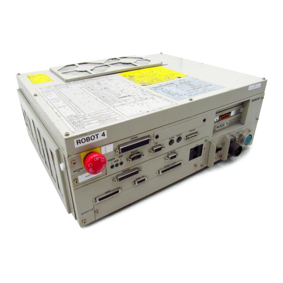
Names of the Robot Controller Components The following figures show the names of the robot controller components. n n n n For VM-D /HM-E series Robot stop button Memory backup battery holder Pilot lamp Output IC box <Left side> Filters (air intake) Names of Robot Controller Components (VM-D/HM-E series) <Front>... - Page 25 n n n n For robot series except VM-D /HM-E <Front> Floppy disk drive (option) FG terminal Robot stop button Memory backup battery holder Pilot lamp Fuse box Power switch Output IC box <Left side> <Right side> Radiating fin Filters (exhaust) Filters (air intake) Note: CN13 is not provided on the VS-E and HS-E series.
- Page 26 Connectors for the VM-D, VS-E, and H -E series (Encoders connected via bus) Connector Marking Serial interface RS232C connector CRT connector Keyboard connector KEYBD Connector for PS/2 MOUSE mouse Connector for teach PENDANT pendant Printer connector PRINTER (Not used.) Connectors for the VS-D, VC-E, H -D and XYC-D series (Encoders connected via parallel interface) Connector Marking Serial interface...
-
Page 27: Robot Controller Specifications
Error codes will be displayed on the external I/O or the operating panel (option). Error display Error messages will be displayed in English on the teach pendant (option). All RC5 models: RC5 for VS-D/-E, H -D/-E, XYC-D: Single-phase, 230 VAC-10% to 230 VAC+10%, Power source RC5 for VC-E: Power capacity VM-D/HM-E: 3.3 kVA... - Page 28 WARNING DO NOT touch fins. Their hot surfaces may cause severe burns. DO NOT insert fingers or foreign objects into openings. Doing so may cause bodily injury. Before opening the controller cover and accessing the inside of the controller for maintenance, be sure to turn off the power switch, disconnect the power cable, and wait 3 minutes or more.
- Page 29 [ 2 ] Outer Dimensions The outer dimensions of the robot controller are shown below. Outer Dimensions of Robot Controller (for VM-D/HM-E series and extended-joint support) Outer Dimensions of Robot Controller (for robot series except VM-D/HM-E)
- Page 30 n n n n Location of IPM boards The table below shows the location of IPM boards for robot series or models. Location Series & models Item VM-6070D Joints IPM model Motor capacity (W) VM-6083D/ Joints VM-60B1D IPM model Motor capacity (W) VS-D Joints IPM model...
-
Page 31: Controller System Configuration
Controller System Configuration 1.4.1 Internal Circuits of the Controller (Typical configuration) The block diagram below shows the internal circuits of an RC5 controller designed for a 6-joint robot. -
Page 32: Typical Robot System Configurations
1.4.2 Typical Robot System Configurations The block diagrams below show typical robot system configurations. To connect encoders via a time-division multiplexed bus: Connect the robot controller (CN12) to the robot unit with a motor/encoder cable (see below). To connect encoders via parallel interface: Connect the robot controller (CN12 and CN13) to the robot unit with a motor cable and encoder cable, respectively. - Page 33 n n n n Robot system configuration with encoders connected via a parallel interface (VS-D, VC-E, H * -D, and XYC-D) System Configuration Example...
-
Page 34: Chapter 2 General Information About The Interface
The compatible mode focuses on compatibility with conventional DENSO robots. Use this mode whenever compatibility is required. For example, when replacing a conventional robot with a new model. However, there are some restrictions on the use of new functions, such as multitasking, in this mode. - Page 35 [ 1 ] Switching from the Teach Pendant Follow the procedure below when switching from one mode to the other from the teach pendant: On the top screen, press [F4 I/O]. " STEP 1 The I/O Monitor window appears. Press [F6 Aux.]. The Auxiliary Functions (I/O) window appears as shown below.
- Page 36 The Choose allocation window appears as shown below. " STEP 3 NOTE: If your robot controller has a built-in DeviceNet master, the Select Port Assignment window will appear instead of the Select I/O Assignment Mode window. Refer to the DeviceNet Master Unit user's manual, Chapter 3, "I/O Assignment."...
- Page 37 [ 2 ] Switching from the Computer Follow the procedure below when switching from one mode to the other from the computer. Start WINCAPSII on the computer. Log in with Programmer. " STEP 1 Start WINCAPSII according to the procedure given in WINCAPSII GUIDE, Chapter 3, Section 3.1.
- Page 38 Select the SETTING command from the Tools menu of DIO Manager. " STEP 3 The Options window will appear as shown below. Click on the Hardware tab in the Options window. " STEP 4 The hardware settings will appear.
- Page 39 Select the desired assignment mode from the right-hand popup menu " STEP 5 in the I/O Allocation frame (Ver. 1.6 or later). Click on OK in the Options window. " STEP 6 The Options window closes. Click on the Connect button "...
- Page 40 Click on the Transfer button. " STEP 8 The Transfer Environment Table window appears. Check off the check box by clicking on the Hard setting field. " STEP 9 Click on the Transfer button. The following message window appears confirming that you are sure to "...
- Page 41 The Transmitting hard setting table window appears displaying a bar graph " STEP 11 that indicates the transfer progress. After the Transmitting hard setting table window disappears, turn the " STEP 12 controller power OFF. Turn the controller power ON. "...
-
Page 42: Types And General Information About I/O Signals
Types and General Information about I/O Signals This section describes the I/O signals for the Robot Controller. The I/O signals are grouped into user I/O signals and system I/O signals. User I/O signals are compatible with conventional signals, including the pin pattern, in compatible mode. -
Page 43: Compatible Mode
2.3.2 Compatible Mode In the compatible mode, the input and output points are arranged in disregard of compatibility with conventional VS series robots. The table below lists the types of I/O signals used in compatible mode. Types of I/O Signals Used in Compatible Mode No. -
Page 44: Using User I/O Signals (Common To Both Modes)
Using User I/O Signals (common to both modes) To use user I/O signals you need to first declare, in the program, the use of user I/O as I/O type variables with a DEFIO command. Next, access the user I/O by writing it to the I/O type variables or reading it. -
Page 45: User Output Commands
2.4.5 User Output Commands There are three types of user output commands, SET, RESET and OUT. The SET and RESET commands turn ON and OFF all user outputs specified by I/O type variables. The OUT command outputs data to a specified user output. SET Command The SET command turns ON all user outputs specified by I/O type variables. -
Page 46: Standard Mode
System I/O Signals 3.1 Types and Functions of System Output Signals (Standard Mode) The table below lists the system output signals used in standard mode. Types and Functions of System Output Signals to be Used in Standard Mode Application Robot initialization Start-up Program execution Robot-in-operation... -
Page 47: Usage Of System Output Signals (Standard Mode)
Usage of System Output Signals (Standard Mode) The usage of each system output signal in standard mode is described below: 3.2.1 Robot Initialization Complete (Output) (1) Function The signal outputs to the external device that a MODE SWITCHING COMMAND is ready to execute from the device. (2) Terminal number No.5 of connector CN10. -
Page 48: Auto Mode (Output)
3.2.2 Auto Mode (Output) (1) Function The signal outputs to the external device that the robot is in auto mode. (2) Terminal number No.6 of connector CN10. (3) Usage Starting the program from the external device requires an EXTERNAL MODE SWITCHING BY MODE SWITCHING COMMAND input and a PROGRAM START BY PROGRAM OPERATION COMMAND input. -
Page 49: External Mode (Output)
3.2.3 External Mode (Output) (1) Function The signal outputs to the external device that the robot is in external mode. (2) Terminal number No.7 of connector CN10. (3) Usage Starting the program from the external device requires an EXTERNAL MODE SWITCHING BY MODE SWITCHING COMMAND input and a PROGRAM START BY PROGRAM OPERATION COMMAND input. -
Page 50: Servo On (Output)
3.2.4 Servo ON (Output) (1) Function The signal outputs to the external device that the power to the motor of the robot is turned ON. (2) Terminal number No.4 of connector CN10. (3) Usage Starting the program requires the power to the motor to be turned ON. This signal is used to light the motor power ON indicator lamp on an external operating panel. -
Page 51: Robot-In-Operation (Output)
3.2.5 Robot-in-operation (Output) (1) Function This signal outputs to the external device that the robot is in operation. (2) Terminal number No.2 of connector CN10. (3) Usage The signal is used to light the robot operating indicator lamp of an external operating panel. -
Page 52: Normal Cpu (Output)
3.2.6 Normal CPU (Output) (1) Function The signal outputs to the external device that the Robot Controller CPU (hardware) is normal. (2) Terminal number No.1 of connector CN10. (3) Usage The signal is used to light the Robot Controller external operating panel ‚... -
Page 53: Robot Failure (Output)
3.2.7 Robot Failure (Output) (1) Function The signal outputs to the external device that a problem (such as a servo error or a program error) occurs with the robot. (2) Terminal number No.3 of connector CN10. (3) Usage The signal is used to light the robot external operating panel error ‚... -
Page 54: Robot Warning (Output)
3.2.8 Robot Warning (Output) (1) Function The signal outputs to the external device that a minor error occurs with an I/O command or during servo processing. Caution: The signal will not be outputted if a minor error, such as a (2) Terminal number No.9 of connector CN10. -
Page 55: Dead Battery Warning (Output)
3.2.9 Dead Battery Warning (Output) (1) Function The signal will be output when the voltage of the encoder back-up battery or memory back-up battery becomes lower than acceptable. (2) Terminal number No.8 of connector CN10. (3) Usage The signal is used to check the timing battery replacement. For example, the battery voltage becomes lower than acceptable. -
Page 56: Continue Start Permitted (Output)
3.2.10 Continue Start Permitted (Output) (1) Function The controller will output this signal when the continue start is permitted. (2) Terminal number No.10 of connector CN10. (3) Usage Use this signal when you want to know whether the continue start is permitted. -
Page 57: Emergency Stop (Output From A Contact)
3.2.12 Emergency Stop (Output from a contact) (1) Function This signal outputs from a contact exclusively designed for an emergency stop circuitry you may configure. It allows red mushroom buttons provided on the front panel of the robot controller, on the teach pendant, and on the operating panel to be used as emergency stop buttons of the facilities. -
Page 58: Types And Functions Of System Input Signals (Standard Mode)
Types and Functions of System Input Signals (Standard Mode) The table below lists the system input signals to be used in standard mode: Types and Functions of System Input Signals to be Used in Standard Mode Application Signal Name Start-up Enable Auto Robot stop Instantaneous... -
Page 59: Usage Of System Input Signals (Standard Mode)
Usage of System Input Signals (Standard Mode) The usage of each system input signal in standard mode is described below. 3.4.1 Enable Auto (Input) (1) Function The signal enables switching of the robot mode to auto mode (shorted ‚ The signal enables switching of the robot mode to manual mode or (2) Terminal number No. -
Page 60: Robot Stop (Input)
3.4.2 Robot Stop (Input) (1) Function The signal stops the robot from the external device by opening the ‚ The signal readies the power to the robot motor to be turned ON by (2) Terminal number No.2 of connector CN8. (3) Input conditions and operation ... -
Page 61: Step Stop (All Tasks) (Input)
3.4.3 Step Stop (All Tasks) (Input) (1) Function Input this signal to step-stop the program being executed from the external device. All tasks will be step-stopped. (2) Terminal No.5 of connector CN8. (3) Input conditions and operation If the state of this signal is changed from ON (shorted) to OFF (open), ‚... -
Page 62: Instantaneous Stop (All Tasks) (Input)
3.4.4 Instantaneous Stop (All Tasks) (Input) (1) Function Input this signal to instantaneously stop the running programs from an external device. All tasks will stop. (2) Terminal number No.7 of connector CN8. (3) Input conditions and operation If the state of this signal is turned from ON (shorted) to OFF (open), the ‚... -
Page 63: Interrupt Skip (Input)
3.4.5 Interrupt Skip (Input) (1) Function If this signal is turned ON (shorted) during execution of the robot operation command, within the range between INTERRUPT ON and INTERRUPT OFF in the program, the correct step operation will immediately stop and the next step will start. - Page 64 Caution: When turning ON (shorting) the interrupt skip signal, at a Robot status Interrupt skip signal (input) ON (shorted) OFF (open) Program start signal (input) ON (shorted) OFF (open) Program reset signal (input) ON (shorted) OFF (open) Program No. select signal (input) ON (shorted) OFF (open) Example of Operation When an Interrupt Skip is Input minimum either the program reset signal or the program...
-
Page 65: Command Execution I/O Signals Dedicated To Standard Mode
Command Execution I/O Signals Dedicated to Standard Mode In standard mode the I/O commands can be executed using command execution I/O signals. I/O commands execute the following. Operate (start and stop) a program for each task. Refer to or change variables from the external device. Refer to or change inputs and outputs from the external device. -
Page 66: Processing I/O Commands
3.5.2 Processing I/O Commands 3.5.2.1 General Information about Processing I/O commands to be executed are processed as shown below. Command Area (input) Data Area (input) Command and Data Area Odd Parity (input) Strobe Signal (input) Status Area (output) Status Parity (output) Command processing complete (output) Robot Error (output) Note ... - Page 67 Set a command area, a data area (if necessary) and command and data area odd parity for the command execution I/O signal from the external device to the Robot Controller. ‚ After the setting is completed, turn ON the strobe signal. Caution: Q Q Q Q The data to be set in Q Q Q Q must be defined more at least 1 msec.
- Page 68 3.5.2.2 Using Each Signal Line [ 1 ] Command and Data Areas This section describes the usage of the command area (4 bits, input), data area 1 (8 bits, input), data area 2 (16 bits, input) and command and data area odd parity (input).
- Page 69 [ 2 ] Strobe Signal (Input) (1) Function This signal informs the Robot Controller that the command area, data areas 1 and 2, and the command and data area odd parity bit have been set. Additionally it directs the start of command processing. Caution: Perform command input with a strobe signal after the system (2) Terminal number No.
- Page 70 [ 3 ] Command Processing Complete (Output) (1) Function The signal outputs to the external device that I/O command processing is completed. (2) Terminal number No. 15 of connector CN10. (3) Usage The signal is used to confirm that I/O command processing is complete, or as a timing signal for obtaining the result of I/O command processing.
- Page 71 [ 4 ] Status Area This section describes the usage of the status area (16 bits, output) and of status area odd parity (output). (1) Function The signal outputs the result of I/O command processing to the external device. (2) Terminal numbers Nos.
-
Page 72: I/O Commands Details
3.5.3 I/O Commands Details 3.5.3.1 List of I/O Commands The table below lists I/O commands. Command area 0001 00000001 Program reset start Program operation 00000010 Program start 00000100 Continue start 00010000 Step stop 00100000 Instantaneous stop 01000000 Reset 0010 00000001 Speed setting External speed and 00000010 Acceleration setting acceleration setting... - Page 73 3.5.3.2 Program Operation Command (0001) (1) Function This command controls the operating state of the program specified in data area 2 based on the setting of data area 1. (2) Format Command area (4 bits, input) 0001 Data area 1 (8 bits, input) 00000001: Program reset start 00000010: Program start 00000100: Continue start...
- Page 74 ‚ Program start This command is executable only in external mode. An error (ERROR2032) will occur in other modes. This command starts the program of the program number specified in data area 2. PRO0 to PRO32767 can be started. If the program number specified in data area 2 is negative, an error (ERROR73E4) will occur.
- Page 75 † Reset This command immediately stops and also initializes the program of the program number specified in data area 2. PRO0 to PR032767 can be stopped. This command cannot be used together with the program start command. To start a step-stopped or cycle-stopped program from the beginning, use the program reset start command.
- Page 76 3.5.3.3 External Speed and Acceleration Setting (0010) (1) Function This command sets the external speed, acceleration and deceleration values selected in data area 1 to the values specified in data area 2. This command is executable only in external mode. An error will occur in other modes.
- Page 77 3.5.3.4 Error Read (0100) (1) Function This command outputs the existing error number to the status area. This command is output to the status area only when the strobe signal remains ON. Caution: This command will not be output if a minor error occurs, such (2) Format Command area (4 bits, input) 0100...
- Page 78 3.5.3.5 Type I Variable Write (0101) (1) Function This command substitutes the value specified in data area 2 for the Type I (integer type) global variable of the number specified in data area 1. (2) Format Command area (4 bits, input) 0101 Data area 1 (8 bits, input) The number of the Type I variable for which a value will be substituted.
- Page 79 Type I Variable Read (0110) 3.5.3.6 (1) Function This command outputs to the status area the value of the Type (integer type) global variable of the number specified in data area 1. (2) Format Command area (4 bits, input) 0110 Data area 1 (8 bits, input) The number of the Type I variable for which a value will be substituted.
- Page 80 3.5.3.7 Mode Switching (0111) (1) Function This command switches the robot mode from the external device to prepare the robot for operation. This command is executable only in auto mode. An error will occur in other modes. Before executing this command, select auto mode on the operating panel or the teach pendant.
- Page 81 ‚ External speed 100 (bit 1) When this bit is set, the external speed, external acceleration and external deceleration of the Robot Controller will be set to 100. ƒ External mode switching (bit 7) When this bit is set, the mode of the Robot Controller will be switched from automatic to external.
- Page 82 3.5.3.8 Clear Robot Failure (1000) (1) Function This command clears a robot failure that has been caused. (2) Format Command area (4 bits, input) 1000 Data area 1 (8 bits, input) Nothing will be input. Data area 2 (16 bits, input) Nothing will be input.
- Page 83 3.5.3.9 I/O Write (1001) (1) Function This command substitutes the status specified in data area 1 for the 8-bit internal I/O area starting from the number specified in data area 2. (2) Format Command area (4 bits, input) 1001 Data area 1 (8 bits, input) The status to be set will be specified in the internal I/O area starting from the number specified in data area 2.
- Page 84 3.5.3.10 I/O Read (1010) (1) Function This command outputs to the lower 8 bits of the status area the status of the 8-bit internal I/O area starting from the number specified in data area (2) Format Command area (4 bits, input) 1010 Data area 1 (8 bits, input) Nothing will be input.
-
Page 85: Example Of Using System I/O Signals In Standard Mode
Example of Using System I/O Signals in Standard Mode This section illustrates an example of starting and stopping the robot using system I/O signals. (1) Equipment setup example This example shown below assumes an equipment setup which allows you to run the robot by operating an external equipment’s operation panel connected via the PLC to the robot controller. - Page 86 Function Example of Equipment Operating Panel Classificati Part Display Display Q Automatic operation indicator lamp R Robot external mode Lamp indicator lamp S Operation OK indicator lamp Q Robot preparation button R Automatic start button Switch S Cycle stop button T Operation/Adjustment selector switch Caution: Actual equipment requires emergency stop, interlock and other functions;...
- Page 87 Worker’s operation and display on Step equipment’s operation panel Equipment power ON Setting operation/adjustment selector switch to operation Operation OK indicator lamp ON Setting Mode selector switch of the operating panel or the teach pendant to AUTO Robot preparation button ON Robot external mode indicator lamp ON Moving robot arm close...
- Page 88 (Continued from preceding page) Worker’s operation and display on Step equipment’s operation panel Equipment’s Automatic Start Button ON Automatic Operation indicator lamp ON Equipment’s Cycle Stop button ON Automatic operation indicator lamp OFF Equipment power OFF Note S S S S In data area 1, the bit to each of "motor ON, CAL execution," "external speed 100" and "External Mode switching"...
-
Page 89: Compatible Mode
System I/O Signals Types and Functions of System Output Signals (Compatible Mode) The table below lists the system output signals used in the compatible mode. Types and Functions of System Output Signals to be Used in Compatible Mode Application Robot power ON Start-up CAL complete External mode... -
Page 90: Usage Of System Output Signals In The Compatible Mode
Usage of System Output Signals in the Compatible Mode The usage of each system output signal in the compatible mode is described below. 4.2.1 Robot Power ON Complete (1) Function PREPARATION START is possible. (2) Terminal number No.9 of connector CN10. (3) Usage OPERATION PREPARATION START will be executed after this signal and the auto mode signal are turned ON after the power was turned ON. -
Page 91: Auto Mode (Output)
4.2.2 Auto Mode (Output) (1) Function The signal outputs to the external device that the robot is in the auto mode. (2) Terminal number No.4 of connector CN10. (3) Usage Starting the program from the external device requires an SWITCH EXT MODE input, a PROGRAM NO. -
Page 92: Servo On (Output)
4.2.3 Servo ON (Output) (1) Function The signal outputs to the external device that the power to the robot motor is turned ON. (2) Terminal number No. 10 of connector CN10. (3) Usage Executing CAL from the external device or starting the program requires the power to the motor to be turned ON. -
Page 93: Cal Complete (Output)
4.2.4 CAL Complete (Output) (1) Function The signal outputs to the external device that CAL is completed. (2) Terminal number No. 11 of connector CN10. (3) Usage This signal is used to determine whether to execute CAL. Once CAL is completed, it does not need to be executed again as long as the power to the Robot Controller is turned ON. -
Page 94: External Mode (Output)
4.2.5 External Mode (Output) (1) Function The signal outputs to the external device that the robot is in the external mode. (2) Terminal number No. 5 of connector CN10. (3) Usage Starting the program from the external device requires an SWITCH EXT MODE input, PROGRAM NO. -
Page 95: Teaching (Output)
4.2.6 Teaching (Output) (1) Function The signal outputs to the external device that the robot is in the manual mode or teaches check mode. (2) Terminal number No. 12 of connector CN10. (3) Usage This signal is used to inform an external operating panel that the robot is teaching when they are installed separately from each other. -
Page 96: Program Start Reset (Output)
4.2.7 Program Start Reset (Output) (1) Function This signal is output to the external device when the robot receives a start signal from the external device and starts to operate. (2) Terminal number No. 6 of connector CN10. (3) Usage ... -
Page 97: Robot-In-Operation (Output)
4.2.8 Robot-in-operation (Output) (1) Function The signal outputs to the external device that the robot is in operation (executing more than one task ). (2) Terminal number No. 2 of connector CN10. (3) Usage The signal is used to light the robot operating indicator lamp of the external operating panel. -
Page 98: Single-Cycle End (Output)
4.2.9 Single-Cycle End (Output) (1) Function The signal outputs to the external device that a single-cycle of the program is completed. Caution Q Q Q Q The single-cycle end signal will be output upon reading (2) Terminal number No. 13 of connector CN10. (3) Usage The signal is used to operate another equipment in synchronization with a single-cycle end of the program. -
Page 99: Normal Cpu (Output)
4.2.10 Normal CPU (Output) (1) Function The signal outputs to the external device that the CPU (hardware) of the Robot Controller is normal. (2) Terminal number No. 1 of connector CN10. (3) Usage The signal is used to light the Robot Controller error indicator lamp of ‚... -
Page 100: Robot Failure (Output)
4.2.11 Robot Failure (Output) (1) Function The signal outputs to the external device that a problem, such as a servo error and a program error, occurs with the robot. (2) Terminal number No. 3 of connector CN10. (3) Usage The signal is used to light the robot failure indicator lamp of an external ‚... -
Page 101: Robot Warning (Output)
4.2.12 Robot Warning (Output) (1) Function The signal outputs to the external device that a minor error has occurred with an I/O command or during servo processing. Caution: The signal will not be output in case of a minor error, such as (2) Terminal number No. -
Page 102: Dead Battery Warning (Output)
4.2.13 Dead Battery Warning (Output) (1) Function The signal will be output when the voltage of the encoder back-up battery or memory back-up battery becomes dangerously low. (2) Terminal number No. 14 of connector CN10. (3) Usage The signal is used to check the timing of battery replacement (lowering of the battery voltage). -
Page 103: Error No. (Output)
4.2.14 Error No. (Output) (1) Function When an error occurs, the signal outputs the error number in a 3-digit (12- bit) hexadecimal code. (2) Terminal numbers No.17 to No.28 of connector CN10. (3) Usage The signal is used to display an error number on the external device. (4) Output conditions The signal will be output when an error occurs. -
Page 104: Continue Start Permitted (Output)
4.2.15 Continue Start Permitted (Output) (1) Function The controller will output this signal when the continue start is permitted. (2) Terminal number No.16 of connector CN10. (3) Usage Use this signal when you want to know whether the continue start is permitted. -
Page 105: Emergency Stop (Output From A Contact)
4.2.17 Emergency Stop (Output from a contact) (1) Function This signal outputs from a contact exclusively designed for an emergency stop circuitry you may configure. It allows red mushroom buttons provided on the front panel of the robot controller, on the teach pendant, and on the operating panel to be used as emergency stop buttons of the facilities. -
Page 106: Types And Functions Of System Input Signals (Compatible Mode)
Types and Functions of System Input Signals (Compatible Mode) The table below lists the system input signals to be used in compatible mode. Types and Functions of System Input Signals to be Used in Compatible Mode Application Enable Auto Motor power ON + operation preparation start CAL execution + operation preparation start... -
Page 107: Usage Of System Input Signals In Compatible Mode
Usage of System Input Signals in Compatible Mode The usage of each system input signal in compatible mode is described below: 4.4.1 Enable Auto (Input) (1) Function The signal enables switching of the robot mode to the Auto mode ‚... -
Page 108: Operation Preparation Start (Input)
4.4.2 Operation Preparation Start (Input) (1) Function By turning ON (short) this signal, input signals to „ described in (3), input conditions and operation will be detected and the robot will automatically start to operate. Input these signals with the system output ROBOT POWER ON COMPLETE turned ON. - Page 109 For the input timing of the operation preparation start signal and to „, see the figure given below. Caution: The operation preparation start signal and each input signal, except the Enable Auto signal, will be turned OFF (falling) upon turning ON of the external mode output is turned ON. Although the robot is made to execute all items at start-up, execute only necessary items at the time of recovery from suspension during operation to reduce recovery time.
-
Page 110: Program No. Select (Input)
4.4.3 Program No. Select (Input) (1) Function The program number to be executed can be specified from the external device by inputting this signal. (2) Terminal numbers No.11 to No.18 of connector CN8. (3) Input conditions and operation This signal is executable only in the external mode. In other modes, an ‚... - Page 111 Example of Program No. Select Signals Program No. (decimal) Input signal Parity The figure below shows an example of a program No. select signal sequence circuit considering parity. Example of Program No. Select Signal Sequence Circuit Lower 4-bit, odd Upper 3-bit, odd Program No.
-
Page 112: Program Start (Input)
4.4.4 Program Start (Input) (1) Function This signal starts the program specified with the program No. select signal from the external device. (2) Terminal number No.10 of connector CN8. (3) Input conditions and operation By switching the status of this signal from ON (open) to ON (shorted) in external mode, operations , ‚... - Page 113 ‚ When the status of the program start signal is switched from OFF to ON with the program step-stopped, the program will resume from the step following the suspended step and stop at the cycle end. Robot status Program start ON (shorted) signal (input) OFF (open)
- Page 114 ƒ When the status of the program start signal is switched from OFF to ON with the program immediately stopped, the program will resume from the suspended step and stop at the cycle end. Robot status Program start ON (shorted) signal (input) OFF (open) Instantaneous stop...
- Page 115 (4) Example of program start signal (rise) ON and (fall) OFF timing Q Q Q Q Example of program start signal rise (ON) timing The figure below shows how to make the program start signal rise with robot system outputs (external mode output and single-cycle end output).
- Page 116 R R R R Example of program start signal fall (OFF) timing a) The following figure shows how to make the program start signal fall with a robot system output (program start reset output). When the robot program starts to run, a program start reset signal is output.
- Page 117 Program start ON (shorted) signal (input) OFF (open) Robot in operation (output) Program start reset (output) Single-cycle end (output) Program Start Signal Rise Output Signal Timing : within 100 ms.
-
Page 118: Program Reset (Input)
4.4.5 Program Reset (Input) (1) Function By turning ON (short) this signal, any program can be forcibly executed from the beginning in a step-stopped state and a suspended state. Caution: Generally, a step-stopped or suspended program resumes (2) Terminal number No.24 of connector CN8. - Page 119 When issued with the Operation Preparation Start The figure below shows the input conditions and an operation timing chart. ‚ Input Program Reset before Operation Preparation Start (1 msec. or more). ƒ After turned ON, this signal may take a maximum of one second for initializing all programs.
-
Page 120: Robot Stop (Input)
4.4.6 Robot Stop (Input) (2) Function The signal stops the robot with the external device by opening the robot ‚ The signal readies the power to the robot motor to be turned ON by (2) Terminal number No.2 of connector CN8. (3) Input conditions and operation ... -
Page 121: Step Stop (All Tasks) (Input)
4.4.7 Step Stop (All Tasks) (Input) (1) Function Input this signal to step-stop the program being executed from the external device. All tasks will be step-stopped. (2) Terminal number No.5 of connector CN8. (3) Input conditions and operation If the status of this signal is changed from ON (shorted) to OFF (open), ‚... -
Page 122: Instantaneous Stop (All Tasks) (Input)
4.4.8 Instantaneous Stop (All Tasks) (Input) (1) Function Input this signal to instantaneously stop the program being executed from the external device. All tasks will instantaneously stop. (2) Terminal number No.7 of connector CN8. (3) Input conditions and operation If the status of this signal is changed from ON (shorted) to OFF (open), ‚... -
Page 123: Clear Robot Failure (Input)
4.4.9 Clear Robot Failure (Input) (1) Function The robot can recover from a stopped state, resulting from a robot failure by turning ON (shorted) the operation preparation start signal with this signal ON (shorted). (2) Terminal number No.25 of connector CN8. NOTE: Operation preparation start signal is inputted through No. -
Page 124: Interrupt Skip (Input)
4.4.10 Interrupt Skip (Input) (1) Function If this signal is turned ON (shorted) during execution of the robot operation command within the range between INTERRUPT ON and INTERRUPT OFF in the program, the operation of the ongoing step will stop and the next step will start. -
Page 125: Continue Start (Input)
Caution: When turning ON (shorted) the interrupt skip signal, at Robot status Interrupt skip ON (shorted) signal (input) OFF (open) Program start ON (shorted) signal (input) OFF (open) Program reset ON (shorted) signal (input) OFF (open) Program No. select ON (shorted) signal (input) OFF (open) Example of Operation When an Interrupt Skip Signal is Input... -
Page 126: Example Of Using System I/O Signals In Compatible Mode
Example of Using System I/O Signals in Compatible Mode This section describes an example of starting and stopping the robot using system I/O signals. (1) Equipment setup example The example shown below assumes an equipment setup which allows you to run the robot by operating an external equipment’s operation panel connected via the PLC to the robot controller. - Page 127 Function Example of Equipment Operating Panel Classification Part Display Display Q Automatic operation indicator lamp R Robot external mode Lamp indicator lamp S Operation OK indicator lamp Q Robot operation button R Automatic start button Switch S Cycle stop button T Operation/Adjustment selector switch Note: Actual equipment requires emergency stop, interlock and other functions.
- Page 128 Worker’s operation and display on Step equipment’s operation panel Equipment power ON Setting operation/adjustment selector switch to operation Operation OK indicator lamp ON Robot preparation button ON Robot external mode indicator lamp ON Moving robot arm close to operation origin, when external mode indicator lamp is ON and operation position...
- Page 129 (Continued from preceding page) Worker’s operation and display on Step equipment’s operation panel Equipment’s Automatic Start Automatic Operation indicator lamp ON Equipment’s Cycle Stop button ON Automatic operation indicator lamp OFF Equipment power OFF Note Q Q Q Q The system inputs for startup here are four types of system inputs – "motor power ON," "CAL execution,"...
-
Page 130: Connector Pin Assignment (Npn Type)
Connector Pin Assignment and I/O Circuits This chapter explains the connector pin assignment and circuits of NPN type (source input and sink output) on an I/O board. I/O boards designed for the use in Japan are of an NPN type. For a PNP type (sink input and source output), refer to Chapter 6, "Connector Pin Assignment and I/O Circuits (PNP type)."... - Page 131 (2) I/O POWER CN7: Power connector for I/O (common to both modes) CN7 Pin Assignment, common to both modes (NPN type) View from the cable side Terminal No. Internal power source output +24V Internal power source output +24V Internal power source output 0V Internal power source output 0V Power input E24V Power input E24V...
-
Page 132: Connector Pin Assignment In Standard Mode
5.1.2 Connector Pin Assignment in Standard Mode (1) OUTPUT CN10: User-/System-output connector (standard mode) CN10 Pin Assignment, in standard mode (NPN type) Terminal Name number Normal CPU Robot in operation Robot failure Servo ON Robot initialization complete Automatic mode External mode Dead battery warning Robot warning Continue start permitted... - Page 133 (2) INPUT CN8: User-/System-input connector (standard mode) CN8 Pin Assignment, in standard mode (NPN type) Terminal Name number Power for robot stop (internal +24V) Robot stop Power for Enable Auto (internal +24V) Enable Auto Step-stop (all tasks) Not used. Instantaneous stop (all tasks) Strobe signal Interrupt skip...
-
Page 134: Connector Pin Assignment In Compatible Mode
5.1.3 Connector Pin Assignment in Compatible Mode (1) OUTPUT CN10: User-/System-output connector (compatible mode) CN10 Pin Assignment, in compatible mode (NPN type) Terminal Name number Normal CPU Robot-in-operation Robot failure Auto mode External mode Program start reset Not used. Not used. Robot power ON complete Servo ON CAL complete... - Page 135 (2) INPUT CN8: User-/System-input connector (compatible mode) CN8 Pin Assignment, in compatible mode (NPN type) Terminal Name number Power for robot stop (internal +24V) Robot stop Power for Enable Auto (internal +24V) Enable Auto Step-stop (all tasks) Continue start Instantaneous stop (all tasks) Operation preparation start Interrupt skip Program start...
-
Page 136: Robot Controller I/O Circuits (Npn Type)
Robot Controller I/O Circuits (NPN type) 5.2.1 User-Input, System-Input and Hand-Input Circuits (NPN type) The following two pages show examples of the user-input, system-input, and hand- input circuit configurations and connections of the robot controller. The maximum allowable capacity of the robot controller's internal power source is 1.3 A. - Page 137 (When the internal power source is used) (When an external power source is used) User-Input and System-Input Circuits (NPN type)
- Page 138 (When the internal power source is used) (When an external power source is used) Hand-Input Circuits (NPN type)
-
Page 139: Robot Stop And Enable Auto Input Circuits
5.2.2 Robot Stop and Enable Auto Input Circuits The Robot Stop and Enable Auto signals are important for safety. The input circuit for these signals must have contacts as shown below. Use the INPUT CN8 (pins 1 and 3) of the robot controller for the power source, irrespective of whether the power source to be used for other I/O signals is the internal power source or an external power source. -
Page 140: User-Output, System-Output, And Hand-Output Circuits (Npn Type)
5.2.3 User-Output, System-Output, and Hand-Output Circuits (NPN type) The following two pages show an example of the configuration and connection of the Robot Controller's user-input output, system-output and hand-output circuit. Since the initial resistance of a lamp is small, the output circuit may be damaged by rush current that flows when the lamp lights. - Page 141 (When the internal power source is used) (When an external power source is used) User-Output and System-Output Circuits (NPN type)
- Page 142 (When the internal power source is used) (When an external power source is used) Hand-Output Circuits (NPN type)
- Page 143 Supplied from the I/O power connector when the internal power source is used Lamp Transistor array Controller Example of Circuit with Lamp (NPN type)
-
Page 144: Emergency Stop Circuit
5.2.4 Emergency Stop Circuit The following figures show the examples of configuration and connection of emergency stop circuit for the robot controller. The red mushroom-shaped switch provided on the robot controller front panel, on the teach pendant, or on the operating panel can be used as a switch for stopping the equipment in case of emergency. - Page 145 5.2.4.2 Dual emergency stop type Emergency Stop Circuit (Dual emergency stop type)
-
Page 146: I/O Power Connector (Npn Type)
5.2.5 I/O Power Connector (NPN type) For the power source to communicate signals between the robot controller and the external device, the internal power source of the robot controller or an external power source is used. The figure below shows an example of connecting I/O power connectors when the internal power source is used, and the figure on the next page shows an example of connecting I/O power connectors when an external power source is used. - Page 147 I/O Power Connection Sample (When an external power source is used) (NPN type) Caution: Use a cable of 0.5 mm or more in size for the wiring between the external power source and the I/O power input connectors of the robot controller.
-
Page 148: Wiring Notes For Robot Controller I/O Connectors (Npn Type)
Wiring Notes for Robot Controller I/O Connectors (NPN type) After the wiring of the controller's I/O connectors is completed, check the following before turning ON the power: Check point (1) Using a circuit tester, check across the "+24V terminal" and "0V terminal" of each connector and across the "E24V terminal"... - Page 149 Connector Terminals and Check Points (NPN type) Connector for hand I/O View from cable side engaging face Terminal Name Meaning Number Hand output 0V (GND) at 1 to 8 terminal output Power 24V power terminal for output hand (E24V) Power Power (GND) terminal for output...
-
Page 150: Connector Pin Assignment (Pnp Type)
Connector Pin Assignment and I/O Circuits This chapter explains the connector pin assignment and circuits of PNP type (sink input and source output) on an I/O board. For an NPN type (source input and sink output), refer to Chapter 5, "Connector Pin Assignment and I/O Circuits (NPN type)."... - Page 151 (2) I/O POWER CN7: Power connector for I/O (common to both modes) CN7 Pin Assignment, common to both modes (PNP type) View from the cable side Terminal No. Internal power source output +24V Internal power source output +24V Internal power source output 0V Internal power source output 0V Power input E0V Power input E0V...
-
Page 152: Connector Pin Assignment In Standard Mode
6.1.2 Connector Pin Assignment in Standard Mode (1) OUTPUT CN10: User-/System-output connector (standard mode) CN10 Pin Assignment, in standard mode (PNP type) Terminal Name number Normal CPU Robot in operation Robot failure Servo ON Robot initialization complete Automatic mode External mode Dead battery warning Robot warning Continue start permitted... - Page 153 (2) INPUT CN8: User-/System-input connector (standard mode) CN8 Pin Assignment, in standard mode (PNP type) Terminal Name number Power for robot stop (internal +24V) Robot stop Power for Enable Auto (internal +24V) Enable Auto Step-stop (all tasks) Not used. Instantaneous stop (all tasks) Strobe signal Interrupt skip...
-
Page 154: Connector Pin Assignment In Compatible Mode
6.1.3 Connector Pin Assignment in Compatible Mode (1) OUTPUT CN10: User-/System-output connector (compatible mode) CN10 Pin Assignment, in compatible mode (PNP type) Terminal Name number Normal CPU Robot-in-operation Robot failure Auto mode External mode Program start reset Not used. Not used. Robot power ON complete Servo ON CAL complete... - Page 155 (2) INPUT CN8: User-/System-input connector (compatible mode) CN8 Pin Assignment, in compatible mode (PNP type) Terminal Name number Power for robot stop (internal +24V) Robot stop Power for Enable Auto (internal +24V) Enable Auto Step-stop (all tasks) Continue start Instantaneous stop (all tasks) Operation preparation start Interrupt skip Program start...
-
Page 156: Robot Controller I/O Circuits (Pnp Type)
Robot Controller I/O Circuits (PNP type) 6.2.1 User-Input, System-Input and Hand-Input Circuits (PNP type) The following two pages show examples of the user-input, system-input and hand- input circuit configurations and connections of the robot controller. The maximum allowable capacity of the robot controller's internal power source is 1.3 A. - Page 157 (When the internal power source is used) (When an external power source is used) User-Input and System-Input Circuits (PNP type)
- Page 158 (When the internal power source is used) (When an external power source is used) Hand-Input Circuits (PNP type)
-
Page 159: Robot Stop And Enable Auto Input Circuits
6.2.2 Robot Stop and Enable Auto Input Circuits The Robot Stop and Enable Auto signals are important for safety. The input circuit for these signals must have contacts as shown below. Use the INPUT CN8 (pins 1 and 3) of the robot controller for the power source, irrespective of whether the power source to be used for other I/O signals is the internal power source or an external power source. -
Page 160: User-Output, System-Output, And Hand-Output Circuits (Pnp Type)
6.2.3 User-Output, System-Output, and Hand-Output Circuits (PNP type) The following two pages show an example of the configuration and connection of the Robot Controller's user-input output, system-output and hand-output circuit. Since the initial resistance of a lamp is small, the output circuit may be damaged by rush current that flows when the lamp lights. - Page 161 (When the internal power source is used) (When an external power source is used) User-Output and System-Output Circuits (PNP type)
- Page 162 (When the internal power source is used) (When an external power source is used) Hand-Output Circuits (PNP type)
- Page 163 Supplied from the II/O power connector when the internal power source is used Lamp Transistor array Controller Example of Circuit with Lamp (PNP type)
-
Page 164: Emergency Stop Circuit
6.2.4 Emergency Stop Circuit The following figures show the examples of configuration and connection of emergency stop circuit for the robot controller. The red mushroom-shaped switch provided on the robot controller front panel, on the teach pendant, or on the operating panel can be used as a switch for stopping the equipment in case of emergency. - Page 165 6.2.4.2 Dual emergency stop type Emergency Stop Circuit (Dual emergency stop type)
-
Page 166: I/O Power Connector (Pnp Type)
6.2.5 I/O Power Connector (PNP type) For the power source to communicate signals between the robot controller and the external device, the internal power source of the robot controller or an external power source is used. The figure below shows an example of connecting I/O power connectors when the internal power source is used, and the figure on the next page shows an example of connecting I/O power connectors when an external power source is used. - Page 167 I/O Power Connection Sample (When an external power source is used) (PNP type) Caution: Use a cable of 0.5 mm or more in size for the wiring between the external power source and the I/O power input connectors of the robot controller.
-
Page 168: Wiring Notes For Robot Controller I/O Connectors (Pnp Type)
Wiring Notes for Robot Controller I/O Connectors (PNP type) After the wiring of the controller's I/O connectors is completed, check the following before turning ON the power: Check point (1) Using a circuit tester, check across the "+24V terminal" and "0V terminal" of each connector and across the "E24V terminal"... - Page 169 Connector Terminals and Check Points (PNP type) Connector for hand I/O View from cable side engaging face Terminal Name Meaning Number Hand output 1 to 8 24V at output terminal Power Power (GND) terminal for output hand (E0V) Power 24V power terminal for output hand (E24V)
-
Page 170: Chapter 7 I/O Wiring
Chapter 7 Multi-core Cables with Connectors Multi-core cables with connectors to be used for the I/O wiring of the Robot Controller are options. Select an appropriate cable from the table given below if necessary. Classification No. I/O Cable Set Input Cable Output Cable Hand I/O Cable I/O Cable... - Page 171 If you do not use optional cables listed on the previous page, use the recommended connectors and cables listed below. Recommended Connectors for I/O Cables and Cable Standards Connector Connector name model/manufacturer PCR-E68FS connector PCS-E68LA cover OUTPUT Honda Communications Industry Co., Ltd. PCR-E20FS connector PCS-E20LA cover HAND I/O...
-
Page 172: Wiring Of Primary Power Source
Robot Controller Power Supply Specifications Item 3-phase power supply (RC5 all models) Single-phase power supply (RC5 for VS-D/-E, H -D, HS-E, XYC-D) Single-phase power supply (RC5 for VC-E) Max. rush current when the power is turned ON... - Page 173 A Auto Mode (Output) ... 28, C CAL Complete (Output) ... Clear Robot Failure (Input) ... Command and Data Areas ... Command Execution I/O Signals Dedicated to Standard Mode... Command Processing Complete (Output) ... Compatible Mode ... 14, 23, Connector Pin Assignment and I/O Circuits (PNP type) Connector Pin Assignment I/O Circuits (NPN type) ...
-
Page 174: System I/O Signals Standard Mode
S Servo ON (Output) ... 30, Single-Cycle End (Output) ... SS mode (Output) ... 36, Standard Mode... 14, 22, Status Area... Step Stop (All Tasks) (Input) ... 41, Strobe Signal (Input)... System I/O Signals Compatible Mode... System I/O Signals Standard Mode ... System Input Signals (Compatible Mode)... - Page 175 Please feel free to send your comments regarding any errors or omissions you may have found, or any suggestions you may have for generally improving the manual. In no event will DENSO WAVE INCORPORATED be liable for any direct or indirect damages resulting from the application of the information in this manual.