Table of Contents
Advertisement
Advertisement
Table of Contents

Related Manuals for Denso HS-G Series


Summary of Contents for Denso HS-G Series
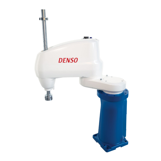
- Page 1 ROBOT Horizontal articulated HS-G SERIES INSTALLATION & MAINTENANCE GUIDE...
- Page 2 Copyright © DENSO WAVE INCORPORATED, 2005-2011 All rights reserved. No part of this publication may be reproduced in any form or by any means without permission in writing from the publisher. Specifications are subject to change without prior notice. All products and company names mentioned are trademarks or registered trademarks of their...
- Page 3 Preface Thank you for purchasing this high-speed, high-accuracy assembly robot. Before operating your robot, read this manual carefully to safely get the maximum benefit from your robot in your assembling operations. Robot series and/or models covered by this manual Model (Note 1) Series Overall arm length...
- Page 4 How this book is organized This book is just one part of the robot documentation set. This book consists of SAFETY PRECAUTIONS, chapters one through three. Chapter 1 Installing Robot Components Provides information about physical site planning, installation procedures, and engineering-design notes for hands.
-
Page 5: Table Of Contents
Contents Chapter 1 Installing Robot Components ........................1 1.1 Preparing a Proper Environment for Installation....................1 1.1.1 Ambient Temperature and Humidity ......................1 1.1.2 Vibration................................. 1 1.1.3 Connecting the Robot Unit and Robot Controller ..................1 1.1.4 Installation Environment of the Robot Unit ....................2 1.2 Mounting the Robot Unit ............................ - Page 6 Chapter 3 Maintenance and Inspection ........................39 3.1 Maintenance & Inspection Intervals and Purposes ..................... 39 3.1.1 Precautions for installation and maintenance of robots for clean room use ..........39 3.2 Daily Inspections..............................41 3.2.1 Check Items..............................41 3.3 Quarterly Inspections ............................43 3.3.1 Check Items and Lubrication........................
-
Page 7: Chapter 1 Installing Robot Components
Chapter 1 Installing Robot Components Preparing a Proper Environment for Installation Before installing the robot unit and robot controller, confirm that the operating environment is in conformity with each item of SAFETY PRECAUTIONS, "Installation Precautions". Also, take proper measures to protect the components from vibration. In an inappropriate environment, the robot will not operate to its full capacity or performance, components may not last long, and unexpected failure may result. -
Page 8: Installation Environment Of The Robot Unit
1.1.4 Installation Environment of the Robot Unit The table below lists the installation requirements for the robot unit. Prepare a highly rigid mount as shown on the next page. Caution: Do not electric-weld the equipment including the robot. A large current may flow through the motor encoder or robot controller resulting in a failure. - Page 9 100 100 pipe 500 or more Caution (1) When the robot operates at high speed, the robot mount undergoes large reaction forces. The mount must be rigid enough so that it will not vibrate or be displaced due to reaction forces.
-
Page 10: Mounting The Robot Unit
Mounting the Robot Unit Caution (1) Before handling or installing the robot unit, be sure to read SAFETY PRECAUTIONS, "Installation Precautions." (2) The grease is applied to the shaft and rack of the Z-axis for lubrication and rust-proof. Do no touch or wipe the shaft and rack so as to keep rust-proof. - Page 11 (HS-G) Step 4 Put the robot unit on the mount bed and secure it with four bolts temporarily. Step 5 Fix the robot unit, referring to Section 1.2.3 "Securing the Robot Unit." Tightening torque: 70 14 Nm (For HS-G series)
-
Page 12: Transporting The Overhead-Mount Type (Hss-G Series)
1.2.2 Transporting the Overhead-Mount Type (HSS-G series) This section gives the typical installation procedure of the robot unit. Caution (1) Since the robot unit weighs approx. 25 kg (55 lbs), prepare a crane and forklift with a hoisting load of 0.2 ton or more. (2) The overhead mounting job must be handled by at least two persons including a qualified operator for sling, crane and forklift operation. - Page 13 Step 2 As illustrated below, wind the belt sling around the robot base two turns and make a knot on the side opposite to the power connector. <HSS-G> Step 3 Load the eyes of the belt sling on the hook of the crane. Wire (Belt sling) <Example of HSS-G series>...
- Page 14 Step 5 While keeping the robot posture, slowly hoist the robot unit with the crane. Caution: Before starting this job, make the work floor clear of obstacles. <HSS-G> Step 6 If the crane hoists the robot unit until it may be turned upside down, stop the crane and have two workers turn the robot unit upside down, as shown below.
- Page 15 Step 7 While having two workers keep the robot unit in the upside-down position, slowly hoist the robot unit with the crane so that the robot base comes into contact with the robot installation face of the overhead-mount frame. Secure the robot unit with four mounting bolts temporarily.
-
Page 16: Securing The Robot Unit
1.2.3 Securing the Robot Unit (1) According to the dimensions specified in the figure below, drill four robot fixing holes and two dowel pin holes in the robot mount where the robot unit is to be anchored. Drilling in the robot mount Drilling in the robot mount For HS/HSS-G series Four robot fixing holes... -
Page 17: Grounding The Robot Unit
1.2.4 Grounding the Robot Unit Ground the grounding terminal of the robot unit using a wire of 5.5 mm or more. Caution: Use a dedicated grounding wire and grounding electrode. Do not share them with other power facilities or welding machines. (HS/HSS-G) Grounding the Robot Unit Installing the Robot Controller... -
Page 18: Electrical Wiring And Air Piping Of The Robot Unit
Secured with two M3 bolts Wiring and Piping Image (HS-G series) 1.4.1 Notes for Wiring and Piping Through a Hollow in the Z-axis Shaft The Z-axis shaft has a hollow through which you may make wiring and piping from the hand control signal connector (CN21) or air piping joints on the top of the 2nd arm. -
Page 19: Reference Drawings For Stays That Clamp Wiring And Piping
1.4.2 Reference Drawings for Stays that Clamp Wiring and Piping When mounting a stay that clamps wiring and piping to the robot unit, be sure to secure it with at least two screws using the four existing internal threads provided in the underside of the second arm. -
Page 20: Prohibition Against Use Of Mechanical End Bolts And Mechanical Stoppers For Wiring Or Piping
CALSET is performed; software limits will become invalid; the robot arm will fail to run as programmed; the robot arm will interfere with its peripheral devices; and so on. 3rd-axis mechanical 2nd-axis mechanical stoppers end bolt 1st-axis mechanical end bolt For HS-G series... -
Page 21: Piping Of Source Air
1.4.4 Piping of Source Air The robot unit is equipped with four air pipes (two of 4 mm and two of 6 mm in diameter) for controlling hands. The maximum of the source air pressure is listed below. Apply dry air to the robot unit. Maximum of source air pressure 0.59 MPa Air Piping of the Robot Unit (HS/HSS-G) -
Page 22: Installing The Flange Kit (Option)
Flange Kit (M4x6) Flange End "A" Flat section of T-axis shaft Installing the Flange Kit (HS/HSS-G) Engineering-design Notes for Robot Hands Refer to the GENERAL INFORMATION ABOUT ROBOT for HS-G SERIES, Chapter 3, Section 3.6 "Engineering-design Notes for Robot Hands"... -
Page 23: Moving Each Axis With Motor Power Off In Emergency Stop
Moving Each Axis with Motor Power OFF in Emergency Stop This section describes how to move each axis with the motor power being OFF when the robot is in an emergency stop. Note that moving the 3rd (Z) and 4th (T) axes requires releasing their brakes beforehand. - Page 24 Moving the axes in an emergency stop Axis How to move the axes 1st axis Move the robot arm by hand. 2nd axis For robot units except UL-Listed ones (1) Reset the emergency stop state as follows. If the emergency stop has been triggered by the teach pendant or mini-pendant, 3rd axis turn the Emergency stop button on the pendant clockwise;...
-
Page 25: Locking Out The Power Switch
Locking Out the Power Switch Lock out the power switch during maintenance and inspection jobs using a commercially available padlock, according to the following procedure. Step 1 Check that the power switch of the robot controller is turned OFF. Step 2 Remove the lockout bar provided on the robot controller. -
Page 26: Chapter 2 Customizing Your Robot
Chapter 2 Customizing Your Robot What Is Customization? You may customize your robot by modifying or setting the following: - Software motion limits for defining the motion space - Mechanical ends for defining the restricted space - Control set of motion optimization - Robot installation conditions You are recommended to define new motion space and restricted space in order to prevent interference with other devices or entanglement of the hand's wiring and... -
Page 27: Modifying Software Motion Limits To Define New Motion Space
Modifying Software Motion Limits to Define New Motion Space 2.2.1 What Is a Software Motion Limit? A limit to the operation range of the robot defined by software is called a software motion limit. Software motion limits become valid after CAL of the robot has been completed and the robot has entered the range set by the limits. -
Page 28: Software Motion Limits (Factory Defaults)
2.2.2 Software Motion Limits (Factory defaults) The table below lists the factory defaults of software motion limits. (1) HS-G series (Floor-mount type) Dust-proof, splash-proof Standard type Cleanroom type type Robot type HS-45**2G HS-45**3G HS-45**2G-W HS-45**3G-W HS-45**2G-P HS-45**3G-P 3rd-axis (Z-axis) stroke... - Page 29 (3) HSS-4555*G (Overhead-mount type, Overall arm length 550 mm) Standard type Dust-proof, splash-proof type Robot type HSS-45551 HSS-45552 HSS-45553 HSS-45551 HSS-45552 HSS-45553 3rd-axis (Z-axis) stroke 150 mm 200 mm 320 mm 150 mm 200 mm 320 mm Positive 155º direction 1st axis Negative -155º...
-
Page 30: Changing Software Motion Limits
2.2.3 Changing Software Motion Limits If the robot interferes with other devices or the air piping and wiring of the hand become taut as the robot arm moves, then change the software motion limits to make the motion space smaller as shown below. Caution: When changing software motion limits, always take into account that the robot arm will motion within the range specified by the initial software motion limits. -
Page 31: Precautions When Changing The Software Motion Limits
2.2.4 Precautions When Changing the Software Motion Limits (1) Confirm the motion space of the robot unit in the actual working environment. (2) When setting the software motion limits, be careful with the units. (3) Specifying too small motion space may cause the robot unit to seem immovable. 2.2.5 Procedure for Changing the Software Motion Limits Described below is the procedure for changing the software motion limits. - Page 32 Step 4 Press the SHIFT key and then press [F12 Maint.]. The Maintenance Functions (Arm) window will appear. Step 5 In the Maintenance Functions (Arm) window, press [F1 M Space]. The Motion Space window will appear as shown below. Select the item to be modified, then press [F5 Change].
- Page 33 Step 6 The numeric keypad will appear as shown below. Enter a desired value using the numeric keys, then press OK. Step 7 The new value will be set on the line of the item selected in the Motion Space window.
-
Page 34: Changing Mechanical Ends To Define New Restricted Space
2.3.1 What is a Mechanical End Change? In the case of the HS-G series, you may change mechanical ends on the 1st through 3rd (Z) axes. When the robot leaves the factory, the mechanical ends are set at points 2 to 3... -
Page 35: Performing Calset
Performing CALSET 2.4.1 What Is CALSET? Calibrating the relationship between position-related information recognized by the robot controller and the actual position of the robot unit is called CALSET. CALSET must be performed when any motor is replaced or when any encoder backup battery goes dead so that the position-related data retained in the encoder is lost as a result. -
Page 36: Preparation For Calset
2.4.2 Preparation for CALSET Press each of the 1st- to 4th-axes against the associated mechanical ends by hand to get the actual positions. CALSET requires some space for bringing each axis into contact with the mechanical end. Caution: (1) When CALSETing, move the axis to be CALSET in the vicinity of the mechanical end, release the brake, and bring the axis into contact with the mechanical end. - Page 37 What is a CALSET position? The limit position of an axis to be CALSET is called a CALSET position. Each axis has a mechanical end in each of the positive and negative directions. The CALSET to be carried out before shipment uses mechanical ends shown below as CALSET positions. (1) CALSET position (HS/HSS-G series) Mounting CALSET bolts on the 4th axis: To CALSET the 4th axis, you need to mount two CALSET bolts on the axis.
-
Page 38: Performing Calset
In the procedure below, releasing the brake is required only for the 3rd and 4th axes. Caution for performing single-axis CALSET in HS-G series The CALSET position of the 3rd axis is related with that of the 4th axis. - Page 39 Step 4 The Brake release setting window appears as shown below. Step 5 Select "Brake released." Step 6 Confirm that there is no danger even if the arm falls as a result of the brake being released. Then press OK.
- Page 40 Step 7 The system message appears asking you whether you want to change the brake settings. Press OK. Step 8 The system message appears informing that the brake is released. Press OK. Step 9 Press the axis to be CALSET against the mechanical end in the CALSET position by hand.
- Page 41 Step 10 Press [F6 CALSET.]. The Set CALSET window appears as shown below. Step 11 Press the axis number to be CALSET to turn it on (green). For other axes that are not to be CALSET, turn it off (black). Press OK.
- Page 42 Step 12 The system message appears asking whether you want to carry out CALSET. Press OK. Step 13 The system message appears informing that CALSET is successfully completed. Press OK. Step 14 Press the ROBOT STOP button. The robot brake becomes activated. Step 15 Turn the ROBOT STOP button to cancel robot stop.
- Page 43 Step 17 Move the CALSET axis in the opposite direction from the mechanical end by manual operation from the teach pendant. The single-axis CALSET of the specified axis is completed. [ 2 ] CALSET of All Axes The CALSET of all axes is called all-axis CALSET. The procedure is the same as that for single-axis CALSET except that you should select all axes in Step 11.
-
Page 44: Setting Control Set Of Motion Optimization
Depending on whether the robot is floor-mounted or overhead-mounted, the optimum operating conditions differ. However, as for horizontal articulated type; the HS-G series (floor-mount type) and HSS-G series (overhead-mount type), the installation conditions are preset at the factory. You do not need to change the factory default of the installation settings. -
Page 45: Chapter 3 Maintenance And Inspection
Chapter 3 Maintenance and Inspection Maintenance & Inspection Intervals and Purposes The table below lists the intervals and purposes of maintenance & inspection required for your robot. Maintenance & Inspection Intervals and Purposes Intervals What to do: Needed: Daily before Inspection jobs specified To use your robot safely. - Page 46 CAUTION When transporting or maintaining the cleanroom type of robot units, take care not to apply an impact or shock to the cover section specified below. An impact or shock applied to the cover section or the resulting deformed cover section may deteriorate the cleanliness performance. No impact or shock is allowed on this cover section.
-
Page 47: Daily Inspections
Daily Inspections 3.2.1 Check Items Before starting operations, check the items listed below every day. Daily Inspections Table Controller What to do: Check: How to check: Criterion Power (Note 1) Connectors (CN1 to Engage the CN10 on the robot No looseness, parts properly Visually controller) and their... - Page 48 Normal Operation of Cooling Fan (Example of HS-G)
-
Page 49: Quarterly Inspections
Quarterly Inspections 3.3.1 Check Items and Lubrication Check the items listed below every three months. Quarterly Inspections Table Controller Check: How to check: Criterion What to do: Power Robot base Measure the No looseness. Tighten the bolts to the mounting bolts tightening specified torque. -
Page 50: Semiyearly Inspections
Semiyearly Inspections 3.4.1 Lubrication Apply the specified grease to the whole Z-axis shaft as shown below every six months. Lubrication Points and Lubricants (HS/HSS-G series) Lubricant Lubrication points Lubricant type Remarks amount Apply the grease to the whole Z-axis Epinoc AP1 2 to 3 cc Z-axis shaft shaft. -
Page 51: Biennial Inspections
Replace the two types of backup batteries listed below and inspect the timing belts every two years. Please contact your DENSO representative to inspect timing belts and to adjust them. Caution (1) The battery used in this device may present a risk of fire or chemical burn if mistreated. -
Page 52: Replacing The Encoder Backup Battery
3.5.2 Replacing the Encoder Backup Battery Replace the encoder backup battery according to the procedure given below. Step 1 Prepare two new backup batteries for replacement. Step 2 Turn the controller power OFF. Step 3 Remove the cover from the robot unit. Four hex. - Page 53 Step 4 Disconnect the old battery (1st one) from the battery board and then remove it from the holder. Battery board Connector Old backup battery Holder (1st one) <HS/HSS-G > Step 5 Connect a new battery (1st one) to the battery board from which you have disconnected the old one in Step 4, and then load it into the holder.
- Page 54 Step 6 Disconnect the remaining old battery (2nd one) from the battery board and then remove it from the holder. Connector Battery board Old backup battery Holder (2nd one) <HS/HSS-G> Step 7 Connect a new battery (2nd one) to the battery board from which you have disconnected the old one in Step 6, and then load it into the holder.
- Page 55 Step 8 Install the cover to the robot unit. NOTE: On the dust- & splash-proof type or cleanroom type, the cover has a packing for sealing. Take care not to lose or pinch it. Tightening toque Hex. socket-head bolt (M3x8): 1.6±0.3 N•m Cover <HS/HSS-G>...
-
Page 56: Replacing The Memory Backup Battery
3.5.3 Replacing the Memory Backup Battery For the replacing procedures of the memory backup battery, refer to the RC7M CONTROLLER MANUAL, Section 6.5 "Replacing the Memory Backup battery." 3.5.4 Setting the Next Battery Replacement Date After replacing the memory backup battery, set the next battery replacement date from the teach pendant, according to the following procedure. -
Page 57: Supplies For Maintenance
Supplies for Maintenance The table below lists the supplies for maintenance. Caution (1) The battery used in this device may present a risk of fire or chemical burn if mistreated. Do not recharge, disassemble, heat above 100C (212F), or incinerate. (2) Dispose of used battery promptly. -
Page 58: Checking The Odometer And Trip Meter
Checking the Odometer and Trip Meter You may check the odometer and trip meter which count traversed distance of each axis in the Odometer window of the teach pendant. The access to the Odometer window is [F6 Set]—[F6 Maint.]—[F5 Odometer]. The Odometer window shows the following items: [Odometer] Shows the total distance of each axis traversed after the robot leaves the factory. - Page 59 Step 4 The Maintenance menu appears as shown below. Press [F5 Odometer]. Step 5 The Odometer window appears as shown below. In the above Odometer window, the J1, J2 and J4 are expressed in number of revolutions and J3 in meter.
-
Page 60: Resetting The Trip Meter To Zero
3.8.2 Resetting the Trip Meter to Zero Step 1 Display the Odometer window as shown below. Access: [F6 Set]—[F6 Maint.]—[F5 Odometer] from the top screen. Press [F6 Reset]. Step 2 The following message appears. Press the OK button. The trip meter has been reset to zero. -
Page 61: Checking The Controller On-Time And The Robot Running Time And Resetting Their User Counters
Checking the Controller ON-Time and the Robot Running Time and Resetting Their User Counters You may check the robot controller ON-time and the robot running time in the Total hours window of the teach pendant. The Total hours window shows the following items: [Total operation] Shows the grand total of the robot controller ON-time counted after the controller leaves the factory. - Page 62 Step 2 The Total hours window appears as shown below. [Total operation] Shows the grand total of the robot controller ON-time counted after the controller leaves the factory. [Total running] Shows the grand total of the robot running time counted after the robot leaves the factory.
-
Page 63: Resetting The User Counters Of The Controller On-Time And The Robot Running Time
3.9.2 Resetting the User Counters of the Controller ON-Time and the Robot Running Time Step 1 Display the Total hours window as shown below. Access: [F6 Set]—[F6 Maint.]— [F1 Total h] from the top screen To reset the user counter of the controller ON-time (Cumu.operation), for example, press [F4 Cumu. - Page 64 Step 3 The user counter of the controller ON-time has been reset to zero as shown below.
-
Page 65: 3.10 Backing Up Projects
- after performing CALSET - after changing RANG values - after replacement of a motor DENSO preserves arm data configured at the time of shipment for 10 years. If your arm data is lost, contact your DENSO representative. Note Arm data refers to CALSET and RANG values in project data, which is unique to individual robots and determines the position of each joint. - Page 66 Step 2 Choose "Get information from the controller for creating a new project." Step 3 Following the project wizard, enter the IP address and the desired backup file name. Step 4 Select "Receive data from the controller after creating the project." Step 5 Close the project.
-
Page 67: 3.10.2 Transfer Arm Data
Step 1 Loading the arm data (***.wam) into the WINCAPSIII project This step is necessary when only arm data is supplied by DENSO. When project data has been backed up, open the project data in WINCAPSIII and proceed to STEP 2. - Page 68 Step 3 Transferring arm data to the robot controller Choose Connect | Transfer data to display the Transfer data window. Select Parameters | Arm parameters and Configuration | CALSET, then press Send. Upon completion of transfer of the CALSET-related arm data, restart the robot controller.
- Page 69 Please feel free to send your comments regarding any errors or omissions you may have found, or any suggestions you may have for generally improving the manual. In no event will DENSO WAVE INCORPORATED be liable for any direct or indirect damages resulting from the application of the information in this manual.