Table of Contents
Advertisement
Quick Links
F10-C20/C25
Model
F10-C30/C35
Model
F10-C50/C55
Model
PATTERN MATCHING SENSOR AMPLIFIER
INSTRUCTION SHEET
Thank you for selecting OMRON product. This sheet
primarily describes precautions required in installing and
operating the product.
Before operating the product, read the sheet thoroughly to
acquire sufficient knowledge of the product. For your
convenience, keep the sheet at your disposal.
©OMRON Corporation All Rights Reserved.
Advertisement
Table of Contents

Related Manuals for Omron F10-C20


Summary of Contents for Omron F10-C20
- Page 1 F10-C50/C55 Model PATTERN MATCHING SENSOR AMPLIFIER INSTRUCTION SHEET Thank you for selecting OMRON product. This sheet primarily describes precautions required in installing and operating the product. Before operating the product, read the sheet thoroughly to acquire sufficient knowledge of the product. For your convenience, keep the sheet at your disposal.
- Page 2 (2) Set the Sensor away from the high voltage machines or the high- Amplifier toward you. tension lines to secure the safety of the operation and the DIN Track maintenance. 〈DIN Track〉 ○ (3) keep the supply voltage within the specified range in this instruction type PFP-100N2 (OMRON) Mounting hook 〈End Plate〉 sheet. type PFP-M(OMRON) (4) If the Sensor or cable has lock mechanisms, be sure to lock the (4)Mounting Space mechanisms securely before use.
-
Page 3: Table Of Contents
forced-air cooling fan or the air-conditioner to keep the Table of Contents temperature under 50 ℃. Specifications/Functions ……………………………1 3. Noise Resistance Components …………………………………………4 ・ Do not wire power lines or high-tension lines alongside lines of I/O Circuit Diagram ………………………………11 the Sensor in the same conduit, otherwise the Sensor may be damaged or malfunction due to induction. Be sure to wire the lines Connection of Serial Communication ……………16 of the Sensor separately from power lines or high-tension lines or... -
Page 4: Specifications/Functions
1. Specifications/Functions ●General Specifications Item F10-C20 / C25 / C30 / C35 / C50 / C55 Head interface (1 channel) Available Head : F10-S30R, or F10-S15R, or F10- Operating temperature 0 ℃ to 50 ℃ S05R, or F10-S15R Operating humidity 35 % to 85 % RH (with no condensation) ●Operation Interface Storage temperature -25 ℃ to 65 ℃ (with no icing) Item F10−C20/C25/C30/C35 F10−C50/C55 Operating environment With no corrosive gas Teaching button Input power supply +21.6 to 26.4 V DC (with ripple (p-p) 10%) Select button UP/DOWN Current consumption 300 mA max. Mode selector TEACH/MON/RUN Insulation resistance 20 M ohm min. (at 500 V DC) Auto-teaching selector OFF/ON Dielectric strength 1,000 V AC at 50 / 60 Hz 1 min Model size selector NORMAL / WIDE Degree of protection IEC60529 IP40 Off-delay timer selector Timer ON / OFF... -
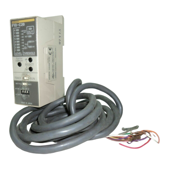
Page 5: Components
2. Components ・ External Input Specifications Item NPN open collector output type PNP open collector output type F10-C20 / C30 / C50 F10-C25 / C35 / C55 Input is ON Short circuited to 0 V with short-current of Short-circuited to Vcc or 9 V min. with ■Amplifiers 1 mA max. or 1.5 V max. max. input voltage +26.4 V DC F10-C20/C25 Input is OFF Open or input voltage of 5 V min. Open or input voltage of 5 V (Max. input voltage : 26.4 V DC) Level Result ●Serial Communication Interface (only F10-C50 / C55) Indicators Indicator Item F10−C50/C55 Interface RS-232C/422 Baud rate 1200bps、2400bps、4800bps、9600bps Status Threshold 19200bps、38400bps(default) Indicators Indicators Data length (fixed) 8bits Parity (fixed) Teach/ ... - Page 6 Displays measurement values (degree of conformity with the registered model). ON : Lit OFF : Not lit F10-C30/C35/C50/C55 Displays the threshold. Level Result Indicators Indicator Displays type of value displayed on the level indicator. F10-C20/C25 PATT(Pattern measurement) :Degree of conformity with model Status Threshold PLN(Plain measurement) DEV :Contrast Indicators/bank Indicators AVE :Average density number display F10-C30/C35/C50/C55 Teach/ display button (Pattern measurement):Degree of conformity with model UP/DOWN selection (Plain measurement):Contrast buttons Mode (Plain measurement):Average density selector Measurement ...
- Page 7 DIP Switch Changing Measurement Items ● PATT A.T.ON ≠ LINE Automat cally switches between PATT ・ PLN PATT/BANK pattern measurement and plain All the DIP switch pins are set to OFF measurement depending on the at the factory. taught model. PATT A.T.OFF NM = RS-232C Executes pattern PATT ・ PLN PATT/BANK /422 measurement only. Bank Selection Mode ● (F10-C30/C35/C50/C55) Automatic Teaching Enters the mode for selecting and PATT ・ PLN PATT/BANK A.T.ON :Teaching area automatically selected setting the bank in TEACH Mode A.T.OFF:Teaching area fixed pattern measurement Measures the degree with which the pattern and the detected ...
- Page 8 A.T.ON ≠ LINE A.T.ON ≠ LINE All the DIP switch pins are set to OFF All the DIP switch pins are set to OFF at the factory. at the factory. RS-232C A.T.OFF NM = A.T.OFF NM = RS-232C /422 /422 ・Model Size OFF Delay Timer WD:Wide mode TMR:Delays the output operation when the control output goes from ON to OFF(Default value is 40ms. NM:Normal mode Refer to the Operation Manual for the Unit for changing procedure). Normal mode Wide mode No Marking:Timer OFF. Teaching area: Divedes the Matching/Not Matching pattern into three, and registers it as three models. ≠: Output ON when object does not match registered model.
-
Page 9: I/O Circuit Diagram
3. I/O Circuit Diagram F10-C25 PNP Models There are gray, green, and red input lines, but they are not used with this model. Take steps to ensure that these lines will not be short-circuited F10-C20 NPN Models with otyer lines. There are gray, green, and red input lines, but they are not used with this Brown (Vcc) model. Take steps to ensure that these lines will not be short-circuited Level in- with otyer lines. dioatora S̲TEACH Yellow (8-level Brown (Vcc) green Level in- LEDs) M̲TEACH Load dioatora purple Black (8-level Result Load ← OUTPUT green indicator Orange LEDs) ... - Page 10 M̲TEACH purple ← ENAB Result Yellow LEDs) indicator S̲TEACH (1-level TRIG Pink purple orange We recommend Result LED) indicator using OMROǸs Amplofi- (1-level White CONT M̲TEACH S82K-01524 Power We recommend er main orange Pink Supply. circit using OMROǸs LED) BANK1 gray S82K-01524 Power ...
-
Page 11: Connection Of Serial Communication
4. Connection of Serial Communication ●I/O Signals Signal Function You can input the measurement trigger and output the measurement OUTPUT Control output results via an RS-232C port. You can also back up the settings in an ENAB Enabled output IBM PC/AT or compatible. Refer to the Operation Manual for the Unit S̲TEACH Stationary object teaching input for details on communications commands. M̲TEACH Moving object teaching input ●1:1 Connection TRIG Measurement trigger input CONT Continuous measurement input System cnfiguration BANK1 Bank switching input (F10-C30/C35/C50/C55) IBM PC/AT or BANK2 compatible BANK3 F10-VR2 RS-232C Cable ・ All input signals are enabled in RUN mode only. ●Switching Banks (F10-C30/C35/C50/C55) You can switch banks by connecting BANK1 to BANK3 as shown below. Bank No BANK1 BANK2 BANK3 Bank 0 ... - Page 12 ●Multidrop Connections A maximum of 31 F10-C50/C55 Sensors can communicate with an IBM ・F10-VR2 RS-232C Cable: D-sub 9-pin connector (2 m) PC/AT or compatible by connecting though RS-232C/422 converters. Recommended Link Adapters (manufactured by OMRON) Pin No. Name Signal Link Adapter B500-AL004 2 SD(TXD) Send data Branching Link Adapter B500-AL001 3 RD(RXD) Receive data SG(GND) Signal ground System configuration Note: Signal and name are in reference to the F10. IBM PC/AT or Link Adapter compatible ・F10-VR4 RS-422 Cable: D-sub 9-pin connector (2 m) Pin No. Name Signal Branching Link Adapter Branching Link Adapter Branching Link Adapter 1 RDB(+) Receive data (+) ...
-
Page 13: Setting Procedure (All Model : Pattern Measurement Only )
Buzzer Press the sounds If using an F10-C30/C35/C50/C55, go to 5 5 teach/display 4 4 step to set the bank number. button . 3 3 If using an F10-C20/C25, go to step 2 2 Not fit for Set the measurement item/bank number a model selection switch to PATT/BANK. Locate the sensing object in the The level indicators are all lit for Bank No. 0 will be displayed. sensing area so that the degree 0.5s and the buzzer sounds of suitability for a model will be twice. indicated. - Page 14 Measurement Item: PATT/PLN Whether measurement is patterned or plain is determined automatically by comparing the contrast with the background within the detection range. When teaching is finished, all the level indicators will light for 0.5 s, and the buzzer will sound twice. Pattern Measurement Plain Measurement The deviation level will become high if the senseing object has a pattern. If the If the set level of measurement item selection is higher than the deviation deviation level is htgher than the set level of measurement item selecton, level, plain measurement will be performed. pattern measurement will be performed. High Plain Measurement with A.T.OFF 8 High Automatic 8 7 Detection Range selection 7 6 Deviation 6 5 The deviation and average Deviation 4 5 density in the Teaching area The portion with the highest ...
-
Page 15: Monitor Mode
On the basis of the registered model, the level indicator Approx.0.5mm (F10- S15R) (=Teaching area) Approx.0.2mm (F10- S05R) indicates the degree of conformity of the sensing object. Closer to Approx.1.6mm (F10- S50R) 8 model in appearance Status indicators(F10-C20/C25) ● 7 6 Detection range at measurement Detection can be enlarged. becomes the following dotted line It becomes the following dotted line Pattern PATT Degree of 5 Plain frame. frame. measuremet coformance ... - Page 16 Plain Measurement Press the UP/DOWN selection buttons to adjust the threshold. Adjust the threshold to the most suitable level Press the teach/display button to change the display (DEV←→AVE). by monitoring the level indicator.Altered threshold values will not be saved unless the mode selector is changed Status indicators(F10-C20/C25) ● once to either RUN or TEACH Pattern Measurement PATT In wide mode, the pattern with the lowest degree of conformance Contrast Plain Plain among the three models is selected. Difference from measurement measurement average density Plain Measurement during teaching Set the threshold values for both DEV (contrast) and AVE (average Status indicators(F10-C30/C35/C50/C55) ● density). If either is lower than the threshold value, the discrimination result will be set to OFF. BANK/STATUS Closer to DEV(contrast) 8 8 model in appearance Press the teach/ Return to bank number 7 7 display no operation is display button Press the ...
-
Page 17: Run Mode
Set the mode selector to RUN. ON When the switch is set to RUN mode, measurements Measurement cycle:Tout CONT are made in response to external input signals. Tout Normal mode:3.6ms Relationship between the F10 I/O terminal operations and ON/OFF ON Wide mode:10.8ms OUTPUT indications in the timing charts are as shown in the following table. Plain measuremnt:7.2ms ON NPN PNP ENAB Indication in (F10-C20/ Signal (F10-C25/ timing charts C30/C50) C35/C55) TRIG Mode Input TRIG (pink) The Sensor in TRIG mode is used for object measurement only once in syn- chronization with the rising edge of the TRIG signal and the result is output. CONT (white) S̲TEACH (yellow) ON TRIG M̲TEACH (purple) Tout Normal mode BANK1 (gray) (see note) ... - Page 18 Bank Change Input You can set the guide light to always ON to turn ON the Please input the number of BANK to "BANK 1 to 3" input lines. The relation of "BANK 1 to 3" and the number of BANK is shown as follows. guide light and execute synchronous measurement. Press the UP selection button when in RUN mode to turn BANK No. BANK 0 BANK 1 BANK 2 BANK 3 BANK 4 BANK 5 BANK 6 BANK 7 ON and OFF the guide light. ...
-
Page 19: External Teaching In Run Mode
●Moving Object Teaching(M̲TEACH) 6. External Teaching in RUN Mode Min 50ms In RUN mode, a model can be registered by external signal input ON M_TEACH using either of the following methods. ON The data of the model is stored in the EEPROM when the teaching process TRIG of the Sensor completes. Therefore, do not turn OFF the Sensor during the Repeat TRIG input teaching process. ON If the Sensor is turned OFF, an EEPROM data error will result when the ENAB Sensor is turned ON again. In this case, perform proper teaching and threshold level adjustments again. -
Page 20: Off-Delay Timer Setting
7. Sysem setting 7.2 Unit Number setting (only F10-C50/C55) 1. Set the mode selector to TEACH, before turning on the power supply. 7.1 Off-delay timer setting 2. While pressing the Teaching button and SELECT UP button, turn on the pow- er supply. 1. Set the mode selector to TEACH, before turning on the power supply. 3. Release the Teaching and SELECT UP buttons, after lighting on the 2 upper 2. While pressing the SELECT UP and Down buttons, turn on the power supply. threshold indicators. 3. Release the SELECT UP and DOWN buttons, after lighting on the 3 center 4. The lighting level and bank number indicators display the current unit number threshold indicators. setting. The lighting level indicators display MSD (most significant digit : 4. The lighting level indicator displays the current off-delay timer setting. 101) and the bank number indicators display LSD (LSD; least significant digit: 100). Ex.) Unit number : 23 8 Lighting Level Indicator Off-delay timer 8 7 Level 8 160ms 7 6 Level 7 140ms 6 Level 6 120ms 5 5 Level 5 ... -
Page 21: Mode Change Plain Measurement Process
7.3 Serial Communicationユ Baud Rate setting 7.4 Mode Change Plain Measuement Process (only F10-C50/C55) 1. Change the Mode selector to TEACH, while the power supply is turning off. 2. Turn on the power supply, while pushing the Teach/display button. 1. Set the mode selector to TEACH, before turning on the power supply. 3. Release the Teach/display button after confirming that the illumination of each 2. While pressing the Teaching button and SELECT DOWN button, turn on the 2 pieces of the upper and the lower side of the Threshold Indicators. power supply. 4. The current Plain Measurement detection range selection mode is displayed 3. Release the Teaching and SELECT DOWN buttons, after lighting on the 2 low- to the Level Indicators. er threshold indicators. 4. The lighting level indicators display the current baud rate setting. Level Indicators that Plain Measurement detection is lighted range selection mode Level 7,8 Mode 1 (Initial setting) 8 Level 1,2 Mode 2 7 ... -
Page 22: Serial Communication Command
8. Serial Communication Command 8.2 Output Response Format (only F10-C50/C55) ■ Normal Response 8.1 Basic Input Format When the input command has been recognized correctly, a response will be re- turned in the following format: The basic format of input commands is described below. Header Unit No. Command Space Response Delimiter @($40) 00 to 31 A($41) to Z($5A) ($20) Space($20), 0($30) to 9($39), CR($0D) 1 byte fixed 2 bytes fixed 2 bytes fixed 1 byte fixed A($41) to Z($5A) 1 byte fixed Header Unit No. Command code Parameters Delimiter ... -
Page 23: List Of Input Commands
8.3 List of Input Commands 8.4 Command Reference Command formats are explained below in alphabetical order. ■ Specifying F10 Operation Commands are input in ASCII. Only uppercase characters can be used. The following commands specify the operation of the F10, such as executing a measurement, changing the bank number, etc. The space character ($20) displays as "̲" (under-bar) in this command Command Function reference. BC Change bank number. MD Acquire previous measurement result. ---------------------------------------------------------------------------------------------- ME Execute image capture measurement once only. ■ BA -BAnk- : Acquire current bank number Begin continuous or synchronous measurements. ---------------------------------------------------------------------------------------------- Execute measurement of image in image memory once only. BA acquires the current bank. - Page 24 ・ Set the following numerical values for <bank̲number>. When this command is recognized, a READY response will be returned. After verifying that this response has been received, the host must Bank No. Content transfer the bank data using the XMODEM (-CRC or ミSUM) protocol. 00 to 07 Bank number When the transfer of all data has been completed, a response indicating Output Response normal completion will be returned. @<unit̲number>BC OK[CR] : Executed correctly @<unit̲number>BC ER[CR] : Not executed correctly Example <unit̲number> 00 to 31: Unit number of Unit to change To transfer data to the current bank in Unit 7: Example Input :@07BL̲CU[CR] Output :@07BL̲READY[CR] To change the bank number of Unit 10 to 7: Input: @10BC̲07[CR] (Transfer data using XMODEM.) Output: @10BC̲OK[CR] Output :@07BL̲OK[CR] ----------------------------------------------------------------------------------------------...
- Page 25 Example ・ Set the following numerical values for <type> To transfer all bank data from Unit 6 to the host: Type Content Input :@06BS̲AL[CR] 0 Contrast threshold(plain measurement) (Data will be transferred using the XMODEM protocol.) 1 Concentration mean threshold (plain measurement) Output :@06BS̲OK[CR] 2 Agreement level threshold(pattern measurement) Measured item selection (pattern/plain) level threshold ---------------------------------------------------------------------------------------------- Output Response ■ HT -Head Type- :Acquire head type @<unit̲number>LG̲<level>[CR] :Executed correctly ---------------------------------------------------------------------------------------------- @<unit̲number>LG̲ER[CR] :Not executed correctly HT acquires the head type. <unit̲number> 00 to 31: Designated unit number Input Command <level> 1 to 7: Threshold level @<unit̲number>HT[CR] ・ Set the following numerical values for <unit̲number>. 8 7.Threshold level ...
- Page 26 ・ Set the following numerical values for <unit̲number>. Input Command @<unit̲number>MC̲<parameter>[CR] Unit No. Content ・ Set the value of <unit̲number> to a number between 00 and 00 to 31 Unit number of the Unit whose threshold level is to be set. 31, or XX. Used when setting all F10 threshold levels. Unit No. Content 00 to 31 Unit number of Unit to change. ・ Set the following numerical values for <type>. XX Used to change all F10's. Type Content 0 Contrast threshold (plain measurement) ・ Set the following numerical values for <parameter>. 1 Concentration mean threshold (plain measurement) <parameter> can be omitted. If omitted, the value defaults to 1. 2 Agreement level threshold (pattern measurement) Parameter Content Measured item selection (pattern/plain) level threshold 0 Signal priority mode Serial priority mode ・...
- Page 27 ・ Set the following numerical values for <parameter>. Unit No. Content <parameter> can be omitted. If omitted, the value defaults to 1 00 to 31 Unit number of Unit performing measurement. Parameter Content When all F10's are forced to perform measurements. Results are returned as a level (0 to 8). When specifying XX as the unit number, set <parameter̲2> to 0. Output Response ・ Set the following numerical values for <parameter̲1>. @<unit̲number>MD̲<comparison̲result><contrast><average̲density>[CR] Parameter 1 Content : Plain measurement 0 Stop measurement. @<unit̲number>MD̲<comparison̲result><agreement>[CR] : Pattern measurement at 1 model 1 Start continuous measurement. @<unit̲number>MD̲<comparison̲result><agreement><agreement>[CR] 2 Start synchronous measurement. : Pattern measurement at 2 models(Wide-mode) (Actual measurement is performed when TRG input line turns ON.) @<unit̲number>MD̲<comparison̲result><agreement><agreement><agreement>[CR] 3 Perform image capture measurement once only. : Pattern measurement at 3 models(Wide-mode) Perform measurement of image in image memory once only. @<unit̲number>MD̲ER[CR] : Not executed correctly <unit̲number>...
- Page 28 <comparison̲result><contrast><average̲density>[CR] ・When a measurement is performed once only and no result is :Plain measurement returned, an OK response will be returned after the single <comparison̲result><agreement>[CR] measurement is completed. : Pattern measurement at 1 model Example <comparison̲result><agreement><agreement>[CR] To perform a single measurement using all connected F10's, and output : Pattern measurement at 2 models(Wide-mode) the results to an external signal line: <comparison̲result><agreement><agreement><agreement>[CR] Input: @XXME̲3̲0[CR] : Pattern measurement at 3 models(Wide-mode) Output: (No response) <comparison̲result> 0: Comparison result was OK 1: Comparison result was NG Measurement results will be output to an output signal line only.
- Page 29 Input: @27ME̲4̲1[CR] Example Output: @27ME̲READY[CR] To acquire the measurement mode of Unit 26: (Measurement performed on image in memory) Input: @26MM[CR] Output: 122[CR] Output: @26MM̲N[CR] (when unregistered) Output: @27ME̲OK[CR] ---------------------------------------------------------------------------------------------- ---------------------------------------------------------------------------------------------- ■ MM -Measure Mode- : Acquire measurement mode ■ RT -ReseT- : Reset ---------------------------------------------------------------------------------------------- Unit No. Content MM acquires the current measurement mode. 00 to 31 Unit number of the Unit to reset. XX Used to reset all F10's. Unit No. Content ------------------------------------------------------------------------------------------------------------------------------------ 00 to 31 Unit number of the Unit whose measurement mode is to be acquired. RT resets the F10. Once RT is recognized, a response is returned and Input Command the reset operation is performed.
- Page 30 ---------------------------------------------------------------------------------------------- Example ■ SG -System data Get- : Acquire system data Parameter Content Value Meaning ---------------------------------------------------------------------------------------------- 0 Unit number 01 to 31 Unit number SG acquires system data information.System data is data that is not 1 Baud rate 1 1200 bps reliant on banks. 2 2400 bps Input Command 3 4800 bps @<unit̲number>SG̲<parameter>[CR] ...
- Page 31 number for <parameter> cannot be specified. @<unit̲number>SS̲ER[CR] : Not executed correctly Normal/Wide Content 0 Set in Normal Mode ・ Set the following numerical values for <parameter> and <value>. Set in Wide Mode. <unit̲number> 00 to 31: Unit number of Unit to set Unit No. Content After the baud rate has been changed, output will remain at the previous 00 to 31 Unit number of Unit on which to perform teaching. baud rate until a response output has been returned. XX Used to perform teaching on all F10's. Example To change the unit number from 24 to 3: Input: @24SS̲0̲03[CR] Output: @24SS̲OK[CR] (Unit number will change to 3 after this response.) Type Content 0 Stationary Object Teaching 1 Moving Object Teaching (start) Moving Object Teaching (abort) ---------------------------------------------------------------------------------------------- ■TC-TeaCh- :Execute teaching ---------------------------------------------------------------------------------------------- Input Command @<unit̲number>TC̲<type>̲<A.T.OFF/ON>̲<pattern/plain>̲...
-
Page 32: Trouble Shooting
CPU runaway, has re- Buzzer indicators fla- 5 sulted. 4 sounds shes and the 3 buzzer sounds. 2 Consult your OMRON representative. Head data read error This LED of 8 1. The EEPROM data of 7 the threshold 6 the Head is not read- Buzzer ... -
Page 33: Dimensions
2 nications. A current exceeding the rated val- Control output (OUTPUT) Reduce the current so ue has flowed to the output transis- and enable output are OFF, that it will not exceed tor and the over-current protective and will not turn ON. the rated value. circuit has been triggered. Consult your OMRON representative, when these signals do not be- come ON even if reduc- ing. Detection Range type error This LED of 8 Perform again the teaching 7 the threshold in TEACH mode or change Detection Range mode ... - Page 34 Note : Specifications subject to change without notice. OMRON Corporation...
- Page 35 Mouser Electronics Authorized Distributor Click to View Pricing, Inventory, Delivery & Lifecycle Information: Omron F10S30R...