Advertisement
Quick Links
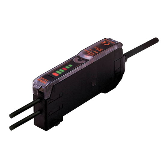
User-Friendly Fiber-Optic Amplifier
Solve Your Basic Sensing Challenges
Easily with the E3X-NA Series
I
Streamlined features provide basic sensing
immediately after plug-in
I
Wire-saving amplifiers reduce installation
time and minimize space requirements
I
Master/slave connector design affords
connectivity for up to 16 wire-saving
amplifiers
I
Use the LED bar display to quickly confirm
sensor performance
I
Optical communication design prevents
mutual interference for up to 5 amplifiers
I
Green LED models address mark-detecting
applications
I
High-speed models have a response time
of 50 µs
I
Select a water-resistant model (IP66 rating)
using an M8 connector
I
Prewired water-resistant models are available
Ordering Information:
Amplifier Units, Connectors, Accessories and Fiber-Optics
Amplifier Units with Cables
I
Type
Part number
NPN output
Standard
E3X-NA11
High-speed
E3X-NA11F
Mark-detection
E3X-NAG11
Water-resistant
E3X-NA11V
Control output
PNP output
E3X-NA41
ON/OFF
E3X-NA41F
E3X-NAG41
E3X-NA41V
E3X-NA
Appearance
Advertisement

Related Manuals for Omron E3X-NA11


Summary of Contents for Omron E3X-NA11
- Page 1 Prewired water-resistant models are available Ordering Information: Amplifier Units, Connectors, Accessories and Fiber-Optics Amplifier Units with Cables Type Part number Control output Appearance NPN output PNP output Standard E3X-NA11 E3X-NA41 ON/OFF High-speed E3X-NA11F E3X-NA41F Mark-detection E3X-NAG11 E3X-NAG41 Water-resistant E3X-NA11V E3X-NA41V...
- Page 2 XS3F-M422-405-A Accessories (Order Separately) Fiber-Optic Cables Mounting Brackets The E3X-NA amplifiers use Omron’s E32-series fiber-optic cables. With a choice of over 80 sensing heads, you are sure to find one that matches your application requirements. Refer to the Appearance Applicable...
- Page 3 Standard models High-speed Mark-detecting Water-resistant Wire-saving Water-resistant detection models models models models (use M8 models connectors) Output type NPN output E3X-NA11 E3X-NA11F E3X-NAG11 E3X-NA11V E3X-NA6 E3X-NA14V PNP output E3X-NA41 E3X-NA41F E3X-NAG41 E3X-NA41V E3X-NA8 E3X-NA44V Light source (wavelength) Red LED (680 nm)
- Page 4 E3X-NA E3X-NA Nomenclature Amplifier Units Sensitivity Indicator 8-Turn Sensitivity Adjuster Operation Mode Selector Use to switch between Lock Button Incident level Indicators Light ON and Dark ON modes. Operation Indicator Timer Switch ON: Timer function is ON. OFF: Timer function is OFF. LED Bar Display Indicators In addition to an operation indicator (orange), the E3X-NA also has...
- Page 5 E3X-NA E3X-NA Operation Output Circuits Output Model Mode Timing chart State of Output circuit selector output transistor E3X-NA11 LIGHT Light ON Incident light Brown E3X-NA6 No incident light Operation E3X-NAG11 (L/ON) Operation indicator indicator E3X-NA11F (orange) (orange) Load E3X-NA11V Photo-...
- Page 6 E3X-NA E3X-NA Engineering Data (Typical) Parallel Operating Range At max. sensitivity. (Use for optical axis adjustment at installation.) E32-T11R E32-TC200 E32-T11L/T12L E3X-NAG@ E3X-NAG@ E3X-NAG@ 0.5 0.6 −50 Distance X (m) Distance X (m) Distance X (m) −100 −100 −100 E3X-NA@F −200 −200 −150...
- Page 7 E3X-NA E3X-NA Number of Turns of Sensitivity Adjuster vs. Sensing Distance E32-T11L E32-D11L E3X-NA@ (V) E3X-NA@ (V) E3X-NA@F Number of turn Number of turns Number of t Sensing Distance vs. Hysteresis E32-T11L E32-D11L E3X-NA@ (V) E3X-NA@ (V) 600 700 Distance (mm) Distance (mm Distance (mm) Distance...
- Page 8 E3X-NA E3X-NA Dimensions Unit: mm (inch) Amplifier Units Amplifier Units with Cables (with Mounting Bracket Attached) Incident level indicators A (See note 1.) Operation indicator E3X-NA11 Cable (See note 2.) E3X-NA11F E3X-NA41 E3X-NA41F 13.05 E3X-NAG11 15.75 E3X-NAG41 64.3 (2.53) 38.6 Two, 2.4 dia.
- Page 9 E3X-NA E3X-NA Wire-Saving Amplifiers Incident level indicators E3X-NA6 Operation indicator E3X-NA8 13.05 15.75 (0.39) Two, 64.3 (2.53) 2.4 dia. 31.5 (1.24) 10.7 38.6 36.7 Hole for optical communications (for preventing mutual interference) Dimensions with Slave Connector Connected Dimensions with Master Connector Connected 71 (2.80) 71 (2.80) 67.5...
- Page 10 E3X-NA E3X-NA Amplifier Unit Connectors (Order Separately) Master Connectors E3X-CN11 2 m (6.56 ft.) 10.7 See note. 4 dia. 14.4 30± 10± 15.1 Note: A 4-dia., 3-conductor, vinyl-insulated round cable (conductor cross-sectional area: 0.2 mm ; insulation diameter: 1.1 mm) is used. Slave Connectors E3X-CN12 2 m (6.56 ft.)
- Page 11 E3X-NA E3X-NA Accessories (Order Separately) Mounting Bracket for E3X-NA , E3X-NA F, and E3X-NAG Models E39-L143 34.8 (1.37) 10.3 Mounting Holes Two, M3 26.8 Two, 3.2 dia. 16± Material: Stainless steel (SUS 304) Four, R1.7 10.3 10 max. Mounting Bracket for E3X-NA V Models E39-L148 R1.7...
- Page 12 E3X-NA E3X-NA Precautions Wiring Precautions Wiring the Amplifier Unit Read the following before using the Amplifier Unit and Sensor to Cable ensure safety. The cable can be extended, provided that the extension wire Power Supply Voltage applied is at least 0.3 mm thick and the total distance no more than 100 m.
- Page 13 E3X-NA E3X-NA Mounting the Amplifier Unit Removal Pull the lock tab of the Amplifier Unit with a flat blade screwdriver Joining Amplifier Units in direction (3) and lift the fiber insertion part in direction (4) as Mount the Amplifier Units one at a time onto the DIN rail. shown below.
- Page 14 E3X-NA E3X-NA Mounting the Fiber Unit Tightening Force The tightening force applied to the Fiber Unit should be as shown below. Protective cover Screw-Mounting Model Cylindrical Model Unlocked Locked Retaining screw (flat head or sunken head) Spring mounting clip (M3 max.) Toothed washers Note: To maintain the fiber properties, confirm that the lock is re-...
- Page 15 E3X-NA E3X-NA Connection Mounting Amplifier Units with Connectors Do not pull or press the Fiber Units. The Fiber Units have a with- stand force of 9.8 N or 29.4 N maximum (pay utmost attention Mounting Connectors because the fibers are thin). 1.
- Page 16 E3X-NA E3X-NA Mounting End Plate (PFP-M) Reflector Use of E39-R3 Reflector Depending on how it is mounted, an Amplifier Unit may move during operation. In this case, use an End Plate. Use detergent, etc., to remove any dust or oil from the surfaces Before mounting an End Plate, remove the clip from the master where tape is applied.
- Page 17 E3X-NA E3X-NA Sensing Distance with Fiber Optic Cables Through-beam Fiber Units Refer to the end of the following table for notes and precautions. Indicates models that allow free cutting. Models without this mark do not allow free cutting. Free-cut : Red light : Green light Application Features...
- Page 18 E3X-NA E3X-NA Application Features Appearance Applicable Sensing distance (mm) Standard object Part Permissible (see notes) Amplifier Unit (Values in parentheses: when number bending (min. sensing using the E39-F1 Lens Unit) radius target: opaque) Flexible Ideal for E3X-NA@ (V) 1.0-mm dia. 4 mm E32-T11 Free-cut...
- Page 19 E3X-NA E3X-NA Application Features Appearance Applicable Sensing distance (mm) Standard object Part Permissible (see notes) Amplifier Unit (Values in parentheses: when number bending (min. sensing using the E39-F1 Lens Unit) radius target: opaque) Chemical- Teflon-cov- E3X-NA@ (V) 4.0-mm dia. 40 mm E32-T12F Free-cut resistant...
- Page 20 E3X-NA E3X-NA Application Features Appearance Applicable Sensing distance (mm) Standard object Part Permissible (see notes) Amplifier Unit (Values in parentheses: when number bending (min. sensing using the E39-F1 Lens Unit) radius target: opaque) Multi-point detection Area sensing E3X-NA@ (V) 2.0-mm dia. E32-M21 25 mm (0.03-mm dia.)
- Page 21 E3X-NA E3X-NA Fiber Units with Reflective Sensors Refer to the end of the following table for notes and precautions. Indicates models that allow free cutting. Models without this mark do not allow free cutting. Free-cut : Red light : Green light Application Features Appearance...
- Page 22 E3X-NA E3X-NA Application Features Appearance Applicable Sensing distance (mm) *1 Standard object Part Permis- (see note) (min. Amplifier Unit number sible sensing target: bending Gold wire) radius Flexible Ideal for mounting on E3X-NA@ (V) 150×150 4 mm E32-D11 moving sections (0.01-mm dia.) E3X-NAG@ 25×25...
- Page 23 E3X-NA E3X-NA Application Features Appearance Applicable Sensing distance (mm) *1 Standard object Part Permis- (see note) (min. Amplifier Unit number sible sensing target: bending Gold wire) radius Coaxial M6coaxial; E3X-NA@ (V) 200×200 25 mm Free-cut E32-CC200 high- (0.01-mm dia.) precision E3X-NAG@ 50×50 positioning...
- Page 24 E3X-NA E3X-NA Application Features Appearance Applicable Sensing distance (mm) *1 Standard object Part Permis- (see note) (min. Amplifier Unit number sible sensing target: bending Gold wire) radius Heat- E3X-NA@ (V) 150×150 35 mm Resists 150°C Free-cut E32-D51 resistant *2; fiber (0.03-mm dia.) sheath materi- M6 screw...
- Page 25 E3X-NA E3X-NA...
- Page 26 E3X-NA E3X-NA...
- Page 27 E3X-NA E3X-NA...
- Page 28 E3X-NA ALL DIMENSIONS SHOWN ARE IN MILLIMETERS. To convert millimeters into inches, multiply by 0.03937. To convert grams into ounces, multiply by 0.03527. OMRON ON-LINE OMRON ELECTRONICS LLC OMRON CANADA, INC. One East Commerce Drive 885 Milner Avenue Global - http://www.omron.com...
- Page 29 High-Precision Fiber-optic Amplifier E3X-NH The E3X-NH Employs a 16-Bit Processor as An Industry First An Automatic Sensitivity Adjustment feature allows stable detection of objects in frequently changing environments Three teach modes for optimal sensing 8-point scaled sensitivity meter is ideal for high precision sensing and through-beam applications at long distances (and clearly displays a...
- Page 30 E3X-NH E3X-NH Specifications Description General-purpose models Timer-function models Part number E3X-NH11 E3X-NH41 E3X-NH21 E3X-NH51 Light source Red (680 nm) Supply voltage 12--24 VDC +10% ripple (p-p) 10 % max. Output Timing —— 40 ms off delay Indicator Operation indicator (orange LED), 8-level incident level indicator (green LED), 13-level threshold indicator (red LED) Circuit protection Output short-circuit protection, reverse polarity on supply...
- Page 31 E3X-NH E3X-NH Nomenclature J E3X-NH11 Operation Indicator (orange) Lit when output is ON. Threshold Indicators (red, 13 levels) Indicates threshold level. Incident Level Indicators (green, 8 levels) Lit depending on the incident light amount. SET Button For teaching or for fine threshold ad- justment UP/DOWN Selector Select UP for increasing the threshold value.
- Page 32 E3X-NH E3X-NH J SENSITIVITY SETTING AND ADJUSTMENT Refer to the following to select the most suitable sensitivity setting method. We recommend that two-point teaching and manual-tuning be tried first. Using the Sensor at the Sensing Slight Differences Sensitivity Setting Maximum Sensitivity Without Objects Application Examples Application Examples...
- Page 33 E3X-NH E3X-NH J SENSITIVITY SETTING (TEACHING) The sensitivity of the E3X-NH is factory-set to maximum. When resetting the sensitivity of the E3X-NH to maximum after with/without-ob- ject teaching or positioning/no-object teaching, follow the steps described below. Maximum Sensitivity Setting Two-point Teach Mode 1.
- Page 34 E3X-NH E3X-NH If teaching is not stable: One-point Teach Mode The threshold indicator (red) will flash. The built-in buzzer will 1. Set the mode selector to TEACH. beep 3 times. Press the SET button once without a target object in the Change the position of the object and the sensing distance sensing area.
- Page 35 E3X-NH E3X-NH J SENSITIVITY ADJUSTMENT (TUNING) Manual-tuning Auto-tuning (Fine Sensitivity Adjustment) (Automatic Sensitivity Compensation) 1. Set the mode selector to TEACH. Note: The auto-tuning function will be disabled if manual-tuning is Press the SET button once without a target object in the utilized.
- Page 36 E3X-NH E3X-NH J SENSITIVITY SETTING—THRESHOLD SETTING AND INDICATORS Threshold indicators Level Maximum Sensitivity Setting Use Through-beam Fibers for detection of opaque objects. • Use the Diffuse Fibers for detection of objects with fixed background. • The threshold should be set to a level slightly higher than the Zero point when detecting objects that completely interrupt light. Diffuse Sensor The number of incident level indicators that are lit will depend on the location of the object.
- Page 37 E3X-NH E3X-NH One-point Teach Mode Through-beam (Dark-ON) Fiber Unit 1. Press the SET button without target in the sensing area. Ideal if it is impossible to perform teaching with the target • fixed in the sensing area. Set the threshold to the value that is ±6% of the incident level.
- Page 38 E3X-NH E3X-NH J THRESHOLD LEVEL AND INDICATOR LEVELS Setting the Initial Threshold To set the initial threshold, perform One-point teaching by pressing the SET button for a minimum of 3 seconds. • As a result of target movement during operation, the middle value between the highest and lowest point on the incident scale will be •...
- Page 39 E3X-NH E3X-NH Dimensions Unit: mm (inch) J AMPLIFIER E3X-NHj1 Operation indicator Threshold indicators (A) (see note) Incident level Note: The mounting bracket can be at- indicators tached to this side. Two, 2.4 dia. Mounting Two, 3.2-dia. holes bracket Two, mounting holes Cable: Polyvinyl chloride-covered cord 4-mm dia.
- Page 40 E3X-NH E3X-NH Installation J CUTTING FIBER J FIBER CONNECTION OR DISCONNECTION PROCEDURES Insert a fiber into the Fiber Cutter and determine the length of the fiber to be cut. The E3X-NH Amplifier has a lock button. Follow these steps to connect or disconnect the fibers to (or from) the E3X-NH Press down the Fiber Cutter in a single stroke to cut the fiber.
- Page 41 E3X-NH E3X-NH J BENDING RADIUS Disconnection 1. Before pulling out the fiber, you MUST first press the lock E39-F11 Sleeve Bender button to release (unlock) the fiber, or you may damage The bending radius of the stainless tube should be as large as the fiber.
- Page 42 E3X-NH E3X-NH Use the attached saddle to secure the end cap of the Protective J ATTACHMENT UNITS Spiral Tube. To secure the Protective Spiral Tube at a position other than the end cap, apply tape to the tube so that the portion Applications becomes thicker in diameter.
- Page 43 E3X-NH E3X-NH When Side-Mounting 4. Finished state (proper cutting state) Approx. 0.5 mm Note: Insert the fiber in the direction indicated by the arrow. Connection Washers (6 dia. max.) Do not pull or press the Fiber Units. The Fiber Units have a withstand force of 9.8 N (1 kgf) or 29.4 N (3 kgf) (pay utmost When side-mounting: attention because the fibers are thin).
- Page 44 Write errors may result at the time of teaching due to power failure or static noise. If any of these occur, re-teach the amplifier. NOTE: DIMENSIONS SHOWN ARE IN MILLIMETERS. To convert millimeters to inches divide by 25.4. OMRON ON- -LINE OMRON ELECTRONICS LLC OMRON CANADA, INC. One East Commerce Drive 885 Milner Avenue Global -- http://www.omron.com...