Advertisement
Quick Links
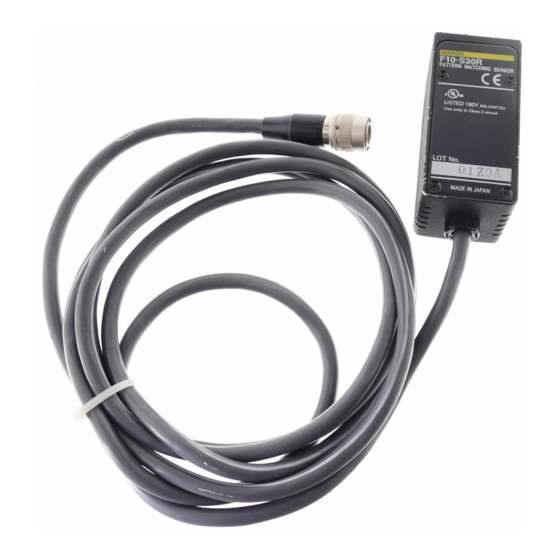
Pattern Matching Sensor
Ordering Information
Heads
Red LED (wide field of vision)
Green LED (medium field of vision)
Green LED (narrow field of vision)
(available soon)
Amplifiers
Standard models
Standard models
Models with bank function
Models with bank function
Models with RS-232C and
Models with RS-232C and
RS-422 interfaces
RS-422 interfaces
Cables
RS-232C (cable length: 2 m)
RS-422 (cable length: 2 m)
8
Downloaded from
Elcodis.com
electronic components distributor
Item
Type
Output
NPN
PNP
NPN
PNP
NPN
PNP
Type
Setting distance
100±10 mm
25 ´ 20 mm
50±5 mm
12 ´ 10 mm
33±3 mm
4.5 ´ 3.5 mm
No. of registered models
1
1
8 (one model per bank)
8 (one model per bank)
F10
Detection range
Model
F10-S30R
F10-S15R
F10-S05R
Model
F10-C30
F10-C50
F10-C55
Advertisement

Related Manuals for Omron F10


Summary of Contents for Omron F10
-
Page 1: Table Of Contents
Item Setting distance Detection range Model Red LED (wide field of vision) 100±10 mm 25 ´ 20 mm F10-S30R Green LED (medium field of vision) 50±5 mm 12 ´ 10 mm F10-S15R Green LED (narrow field of vision) 33±3 mm 4.5 ´... - Page 2 Specifications Ratings/Characteristics Heads Optical and Lighting System Specifications Specifications Item Item F10-S30R F10-S15R F10-S05R Setting distance 100±10 mm 50±5 mm 33±3 mm Sensing area 25 mm ´ 20 mm 12 mm ´ 10 mm 4.5 mm ´ 3.5 mm Guide light projection size...
- Page 3 Input is OFF: Open or input voltage of 5 V max. Input is OFF: Open or input voltage of 5 V min. (Max. input voltage: +26.4 VDC) Head interface (1 channel) Available Head: F10-S30R, F10-S15R, or F10-S05R Indicators Result indicator: 1 orange LED Level indicators:...
- Page 4 Engineering Data Data Characteristics F10-S30R Rotation · The following data is obtained on the basis of sample sensing objects, each of which is as large as this size (A). (Typical example) · The Head is inclined 15° to the sensing object.
- Page 5 F10-S05R available soon Downloaded from Elcodis.com electronic components distributor...
- Page 6 Nomenclature Heads F10-S30R Teaching area Guide light (green) F10-S30R with 2-m standard cable Object lighting (red) 100±10 mm Sensing side Sensing area (field of vision) F10-S15R Teaching area Guide light (blue) Object lighting (green) 50±5 mm F10-S15R with 2-m standard cable...
- Page 7 Deviation level Plain measurement: Difference from average density Pattern Measurement Also displays bank number for F10-C30/C35/C50/C55 Measures the degree with which the pattern and the (5) Starts teaching. detected image match to differentiate OK and NG images. Switches display item.
-
Page 8: Model
Output ON when object does not match registered model. Output ON when object matches registered model. External Input (F10-C50/C55 only) LINE: Executes external input in RUN mode via input line. RS-232C/422: Executes external input in RUN mode via serial communications. -
Page 9: F10-Vr2
You can input the measurement trigger and output the measurement results via an RS-232C port. You can also back up the settings in an IBM PC/AT or compatible. Refer to the Operation Manual for the Unit for details on communications commands. 1:1 Connection System configuration Use F10 products for items marked with an asterisk. IBM PC/AT or compatible *F10-VR2... -
Page 10: F10-Vr4
Multidrop Connections A maximum of 31 F10-C50/C55 Sensors can communicate with an IBM PC/AT or compatible by connecting though RS-232C/422 converters. Recommended Link Adapters (manufactured by OMRON) Link Adapter: B500-AL004 Branching Link Adapter: B500-AL001 Note: When using a B500-AL004 Branching Link Adapter, be sure to enable terminating resistance and include a terminating resistance in the last link adapter according to the following: Between RDA(- -) and RDB(+): 220 W (1/2 W min.) -
Page 11: F10-C20
Operation I/O Circuit Diagram F10-C20 NPN Models F10-C25 PNP Models There are gray, green, and red input lines, but they are not used with There are gray, green, and red input lines, but they are not used with this model. Take steps to ensure that these lines will not be short-cir- this model. - Page 12 (2) Make the automatic teaching and model size settings on the DIP switch. If using an F10-C30/C35/C50/C55, go to step (3) to set the bank number. If using an F10-C20/C25, go to step (5). (3) Set the measurement item/bank number selection switch to PATT/BANK. Bank No. 0 will be displayed.
- Page 13 Measurement continues as long as the selector is set to MON. Pattern Measurement On the basis of the registered model, the level indicator indicates the degree of conformity of the sensing object. · · Status indicators, F10-C20/C25 Status indicator, F10-C30/C35/C50/C55 Pattern Press the Switch Degree of...
- Page 14 Plain Measurement Press the teach/display button to change the display (DEV-AVE). · Status indicators (F10-C20/C25) PATT DEV lit Deviation level Deviation Plain measurement level is Difference from average small density during teaching · Status indicator (F10-C30/C35/C50/C55) Plain measurement Deviation level is...
- Page 15 (1) Set the mode selector to RUN. When the switch is set to RUN mode, measurements are made in response to external input signals. Relationship between the F10 I/O terminal operations and ON/OFF indications in the timing charts are as shown in the following table. Signal...
- Page 16 5. The bank is being switched. 6. The guide light is being turned ON or OFF. RS-232C/422 Command Inputs (F10-C50/C55 Only) Communications with external devices, such as an IBM PC/AT or compatible, is possible via the RS-232/422 port. Refer to the Operation Manual for the unit for details on the communications commands.
- Page 17 2.The data is illegal. buzzer sounds. Head type error Connect an F10-S30R/S15R/S05R to the head. An F10-S30/S15 is connected to the head. This LED of the threshold Buzzer indicators flashes and the sounds buzzer sounds. Teaching data setting error Perform the teaching of the Sensor in TEACH mode.
- Page 18 Either the send buffer or receive buffer has Change the communications settings. Buzzer become full during communications. Receive buffer overflow sounds Wait for a response from the F10, then This LED of the threshold send the command. indicators flashes and the buzzer sounds three times.
- Page 19 Heads F10-SjR The Mounting Bracket can be attached to this side as well. Ferrite core (75) 14.7-dia. connector (125) 5.8-dia. Vinyl-insulated round cable, standard length: 2 m Mounting hole Mounting hole 2-M4 pan-head screw (16.7) Mounting Dimensions Two, M4 37±0.2...
- Page 20 Precautions Setup General Precautions The F10-Cj Amplifier radiates heat. If more than one Unit is The user must operate the product according to the performance installed side-by-side, make sure that there is a minimum space of specifications described in the brochure.
- Page 21 The product has been produced at OMRON Ayabe which obtained ISO9001-approval for its quality system and ISO14001-approval for its environmental management system from international certification bodies. ALL DIMENSIONS SHOWN ARE IN MILLIMETERS. To convert millimeters into inches, multiply by 0.03937. To convert grams into ounces, multiply by 0.03527.