Omron E3X-NA Manual
Fiber amplifier
Hide thumbs
Also See for E3X-NA:
- Manual (29 pages) ,
- Datasheet (12 pages) ,
- Instruction manual (44 pages)
Table of Contents
Advertisement
Quick Links
Manual Fiber Amplifier
E3X-NA
Simple and Easy-to-Use Amplifiers
with a Sensitivity Adjuster
Provided as a Standard Feature
■ Intuitive LED bar display shows light levels at a glance.
■ Utilizes OMRON's innovative wire-saving connector.
■ Reduced wiring and space requirements for power
lines.
■ Optical communications prevents mutual interference
for up to 5 amplifiers
■ High-speed detection, mark-detecting, and water-
resistant models also available.
Be sure to read Safety Precautions on
page 10.
Ordering Information
Amplifier Units
Amplifier Units with Cables
Item
Standard models
With self-diagnosis function
High-speed detection models
Mark-detecting models
Water-resistant models
Amplifier Units with Connectors
Item
Standard models
Water-resistant
models
(M8 connectors)
Amplifier Unit Connectors (Order Separately)
Item
Master Connector
Slave Connector
http://www.ia.omron.com/
Appearance
Applicable Connector
Appearance
(order separately)
Master
Slave
XS3F-M421-40@-A
XS3F-M422-40@-A
Note: Stickers for Connectors are included as accessories.
Appearance
Control output
NPN output
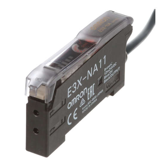
E3X-NA11
E3X-NA21
E3X-NA11F
ON/OFF output
E3X-NAG11
E3X-NA11V
Control output
E3X-CN11
E3X-CN12
ON/OFF output
Cable length
conductors
2 m
(c)Copyright OMRON Corporation 2007 All Rights Reserved.
Model
PNP output
E3X-NA41
E3X-NA51
E3X-NA41F
E3X-NAG41
E3X-NA41V
Model
NPN output
PNP output
E3X-NA6
E3X-NA8
E3X-NA14V
E3X-NA44V
No. of
Model
3
E3X-CN11
1
E3X-CN12
1
Advertisement
Table of Contents

Related Manuals for Omron E3X-NA


Summary of Contents for Omron E3X-NA
-
Page 1: Ordering Information
E3X-NA14V E3X-NA44V XS3F-M422-40@-A (M8 connectors) Amplifier Unit Connectors (Order Separately) Note: Stickers for Connectors are included as accessories. No. of Item Appearance Cable length Model conductors Master Connector E3X-CN11 Slave Connector E3X-CN12 http://www.ia.omron.com/ (c)Copyright OMRON Corporation 2007 All Rights Reserved. -
Page 2: Mounting Brackets
Note: Refer to Introduction to Sensor I/O Connectors for details. Accessories (Order Separately) Mounting Brackets End Plate Appearance Applicable models Model Quantity Appearance Model Quantity E3X-NA@ E3X-NA@F E39-L143 PFP-M E3X-NAG@ E3X-NA@V E39-L148 http://www.ia.omron.com/ (c)Copyright OMRON Corporation 2007 All Rights Reserved. -
Page 3: Ratings And Specifications
Destruction: 50 times (for connection to the Amplifier Unit and the adjacent Connector) tions Housing Polybutylene terephthalate (PBT) Material Contact Phosphor bronze/gold-plated nickel Weight Approx. 55 g Approx. 25 g (packed state) http://www.ia.omron.com/ (c)Copyright OMRON Corporation 2007 All Rights Reserved. - Page 4 E32-T61-S + E39-F2 E32-T61-S + E39-F1 3000 E32-T84S-S E32-T61-S E32-T11F 1050 Environment- resistive E32-T12F 1600 Chemical models E32-T14F resistant E32-T51F E32-T81F-S E32-T51V E32-T51V + E39-F1V Vacuum E32-T54V resistant E32-T54V + E39-F1V E32-T84SV http://www.ia.omron.com/ (c)Copyright OMRON Corporation 2007 All Rights Reserved.
- Page 5 2 to 6 (center 4) Convergent- reflective E32-L25L 5.4 to 9 (center 7.2) E32-L86 4 to 10 E32-L16 0 to 15 0 to 13 E32-D51 Heat resistant E32-D81R/E32-D61 Environment- E32-D73 resistive models E32-D12F Chemical resistant E32-D14F http://www.ia.omron.com/ (c)Copyright OMRON Corporation 2007 All Rights Reserved.
- Page 6 Special beam E32-T11L/E32-T12L E32-D11R/E32-D12R/E32-D15XR/E32-DC200BR(B4R) E32-D14LR E32-D15YR/E32-D15ZR Standard E32-DC200/E32-D15X/E32-DC200B(B4) E32-D14L Reflective E32-D15Y/E32-D15Z E32-D11L E32-CC200R Special beam E32-CC200 E32-D32L E32-C31/E32-D32 E32-T14 Application Label detection specific E32-G14 Refer to E32 Series for details on Fiber Units. http://www.ia.omron.com/ (c)Copyright OMRON Corporation 2007 All Rights Reserved.
- Page 7 Number of Turns of Sensitivity Adjuster vs. Sensing Distance E32-T11L E32-D11L E3X-NA@(V) E3X-NA@(V) E3X-NA@F E3X-NA@F Number of turns Number of turns Sensing Distance vs. Differential Travel E32-T11L E32-D11L E3X-NA@(V) E3X-NA@(V) 600 700 Distance (mm) Distance (mm) http://www.ia.omron.com/ (c)Copyright OMRON Corporation 2007 All Rights Reserved.
-
Page 8: I/O Circuit Diagrams
Incident light Self-diagnosis output No incident light Operation indicator Incident level Blue DARK ON (orange) indicators Dark-ON (D-ON) (4 green, 1 red) Output transistor Load Operate (relay) Reset (Between brown and black leads) http://www.ia.omron.com/ (c)Copyright OMRON Corporation 2007 All Rights Reserved. - Page 9 Sensitivity indicator 8-turn sensitivity adjuster Operation Selector Use to switch between Incident level indicators Lock lever Light-ON and Dark-ON Timer switch Operation Indicator ON: Timer function is ON. OFF: Timer function is OFF. http://www.ia.omron.com/ (c)Copyright OMRON Corporation 2007 All Rights Reserved.
-
Page 10: Safety Precautions
Remove the Protective Cover and raise the lock lever to pull out the appropriate adjustments using the sensitivity adjuster. fiber. The mutual interference prevention function will not operate when the E3X-NA is used side-by-side with E3X-DA-N models. ● Mounting Protective cover DIN Track Mounting/Removal... - Page 11 Connectors without separating them from other Amplifier Units 2. Remove the clip by rotating the Amplifier Unit. first.) Press down Rotate Lever Remove Pull Strengths for Connectors (Including Cables) E3X-CN11: 30 N max. E3X-CN12: 12 N max. http://www.ia.omron.com/ (c)Copyright OMRON Corporation 2007 All Rights Reserved.
- Page 12 Note: 1. The mounting bracket can also be used on side A. 2. 4-dia. vinyl-insulated round cable with 3 conductors (Conductor cross section: 0.45 , Insulator diameter: 1.1 mm), Standard length: 2 m. http://www.ia.omron.com/ (c)Copyright OMRON Corporation 2007 All Rights Reserved.
- Page 13 Dimensions with Master Connector Connected Dimensions with Slave Connector Connected 67.5 67.5 64.3 64.3 E3X-CN12: E3X-CN11: 2.6 dia. 4.0 dia. 31.5 31.5 17.45 12.95 12.95 11.55 1.8 5.1 3.9 1.8 5.1 3.9 http://www.ia.omron.com/ (c)Copyright OMRON Corporation 2007 All Rights Reserved.
- Page 14 Mounting bracket (E39-L148) (Order separately) Two, M3 Stainless steel (SUS304) Amplifier Unit Connectors Sensor I/O Connectors Accessories (Order Separately) Mounting Brackets End Plates Refer to E32 Series for details on Fiber Units. http://www.ia.omron.com/ (c)Copyright OMRON Corporation 2007 All Rights Reserved.
-
Page 15: General Precautions
Brown Sensor Black insert a load when Sensor connecting the power Blue supply. Blue ● Operating Environment Do not use a Sensor in an environment where there are explosive or inflammable gases. http://www.ia.omron.com/ (c)Copyright OMRON Corporation 2007 All Rights Reserved. - Page 16 Receiver. Sensor sensing distance.) (Light may enter even if the Sensors are separated by Sensor Sensor more than the sensing distance.) θ θ Adjust the Lowering the sensitivity will generally help. sensitivity. http://www.ia.omron.com/ (c)Copyright OMRON Corporation 2007 All Rights Reserved.
- Page 17 Repeated Bending other terminals. Normally, the Sensor cable should not be bent repeatedly. (For bending-resistant cable, see Attachment to Moving Parts page 24.) http://www.ia.omron.com/ (c)Copyright OMRON Corporation 2007 All Rights Reserved.
-
Page 18: Power Supply
Approx. 13,000 times Approx. 500,000 times The testing conditions of the standard cable and robot cable are different. Refer to the values in the above table to check bend-resistant performance under actual working conditions. http://www.ia.omron.com/ (c)Copyright OMRON Corporation 2007 All Rights Reserved. -
Page 19: Optical Axis Adjustment
Optical axis Optical axis Emitter Receiver Receiver Incident indicator or Operation indicator Emitter Mechanical axis Optimum value Emission beam Reception area Incident indicator or Operation indicator http://www.ia.omron.com/ (c)Copyright OMRON Corporation 2007 All Rights Reserved. - Page 20 Cleaning • Keep organic solvents away from the Sensor. Organic solvents will dissolve the surface. • Use a soft, dry cloth to clean the Sensor. http://www.ia.omron.com/ (c)Copyright OMRON Corporation 2007 All Rights Reserved.
- Page 21 Warranty and Limitations of Liability WARRANTY OMRON's exclusive warranty is that the products are free from defects in materials and workmanship for a period of one year (or other period if specifi ed) from date of sale by OMRON. OMRON MAKES NO WARRANTY OR REPRESENTATION, EXPRESS OR IMPLIED, REGARDING NON-INFRINGEMENT, MERCHANTABILITY, OR FITNESS FOR PARTICULAR PURPOSE OF THE PRODUCTS.
- Page 22 Mouser Electronics Authorized Distributor Click to View Pricing, Inventory, Delivery & Lifecycle Information: Omron E3X-NAG11 E3X-NAG41...