
Related Manuals for Endress+Hauser HART Micropilot S FMR533


Summary of Contents for Endress+Hauser HART Micropilot S FMR533
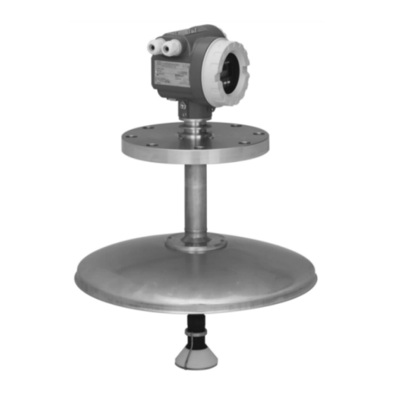
- Page 1 Operating Instructions Micropilot S FMR533 Level-Radar BA00209F/00/EN/13.10 71127744 Valid as of software version V 01.03.00 (amplifier) V 01.03.00 (communication)
- Page 2 An overview of all device functions can be found on → ä 84. The operating manual BA00217F/00/EN "Description of Instrument Functions" provides an extensive description of all device functions, which can be found on the enclosed CD-ROM. The Operating Instructions can also be found on our homepage: www.endress.com Endress+Hauser...
-
Page 3: Table Of Contents
Incoming acceptance, transport, storage ..9 Contact addresses of Endress+Hauser ... 77 Installation Conditions ..... . 10 Installation instructions . -
Page 4: Safety Instructions
This device may not cause harmful interference, and this device must accept any interference received, including interference that may cause undesired operation. " Caution! Changes or modifications not expressly approved by the part responsible for compliance could void the user’s authority to operate the equipment. Endress+Hauser... -
Page 5: Notes On Safety Conventions And Symbols
A connection made to the plant grounding system which may be of type e.g. neutral star or equipotential line according to national or company practice. Temperature resistance of the connection cables t >85°C States, that the connection cables must be resistant to a temperature of at least 85 °C. Endress+Hauser... -
Page 6: Identification
Device designation 2.1.1 Nameplate The following technical data are given on the device nameplate: Order No max. pressure Degree of protection (see Order Information) in tank ENDRESS+HAUSER measuring range MICROPILOT S 0560 Order Code: if modification Ser.-No.: XXXXXXXXXXX see sep. label Messbereich max. - Page 7 NMi witnessed initial verificat. (<1mm) type approval G PTB witnessed initial verificat. (<1mm) type approval Not selected; Inventory control version (3mm) Special version, TSP-No. to be spec. Additional option: A Basic version Special version Marking: 1 Tagging (Tag), see additional spec. FMR533- Complete product designation Endress+Hauser...
-
Page 8: Scope Of Delivery
The device complies with the applicable standards and regulations as listed in the EC declaration of conformity and thus complies with the statutory requirements of the EG directives. Endress+Hauser confirms the successful testing of the device by affixing to it the CE mark. -
Page 9: Mounting
Follow the safety instructions and transport conditions for devices of more than 18 kg. 3.2.3 Storage Pack the measuring device so that is protected against impacts for storage and transport. The original packing material provides the optimum protection for this. The permissible storage temperature is -40 °C to +80 °C. Endress+Hauser... -
Page 10: Installation Conditions
Micropilot S FMR533 4 to 20 mA HART Installation Conditions 3.3.1 Dimensions 65 (2.56) 85 (3.35) 68 (2.68) 94 (3.7) ENDRESS+HAUSER Micropilot II marker E+H UNI flange (max. 1 bar) flange hub Ø 99.5 (3.92) Ø 280 (11.02) DIN, ANSI, JIS, JPI Ø... - Page 11 The FMR532 with planar antenna is recommended for stilling wells with a diameter DN150 (6") and larger. • Metallic screens (3) mounted at a slope spread the radar signals and can, therefore, reduce interference echoes. Please contact Endress+Hauser for further information. Endress+Hauser...
- Page 12 25 m (82 ft) 1.5 m 38 m (114 ft) 2.3 m L00-FMR53xxx-14-00-00-xx-003 40 m (120 ft) 2.4 m " Caution! Make sure that only one tank wall (not two tank walls) is directly hit by the radar beam! Endress+Hauser...
- Page 13 150 to 300 (6 to 12) Behaviour if measuring range is exceeded The behaviour in case of the measuring range being exceeded can be freely set: The default setting is a current of 22 mA and the generation of a digital warning (E681). Endress+Hauser...
- Page 14 Media group DC ( Examples non-conducting liquids, e.g. liquefied gas (LPG). For more information please contact 1.4 to 1.9 your Endress+Hauser representative. non-conducting liquids, e.g. benzene, oil, toluene, white products, black products, 1.9 to 4 crudes, bitumen/asphalts, … 4 to 10 e.g.
- Page 15 (mounting flange) to the medium surface at maximum level. L00-FMR533xx-15-00-00-en-001 Blocking distance (BD) Free space (Storage tank) 1 m (40") (→ ä 10) from flange 1 mm accuracy under reference conditions Note! Inside the blockding distance, a reliable measurement can not be guaranteed. Endress+Hauser...
-
Page 16: Installation Instructions
(refer to the following fig.). It has to be possible to remove the cover in order to mount the antenna. The device can be mounted on the manway cover with a weld-on flange with a neck. Please consider the maximum height of the nozzle (H max. = 200 mm (8")) for the diameter of the basis. Endress+Hauser... - Page 17 4 bolts hinged flange hinge manway min. 10 mm L00-FMR533xx-17-00-00-en-003 H max. (=inside diameter of manway) (=maximum height of nozzle) ≥ 500 mm (≥ 20") Standard installation 200 mm (8") ≥ 600 mm (≥ 24") Hinged flange 200 mm (8") Endress+Hauser...
- Page 18 Proceed as follows to turn the housing to the required position: • Undo the fixing screws (1) • Turn the housing (2) in the required direction • Tighten up the fixing screws (1) Allen key 4 mm (0.16 in) tighten strongly by hand L00-FMR533xx-17-00-00-en-008 Endress+Hauser...
- Page 19 Installation with Endress+Hauser UNI flange Installation hints Endress+Hauser UNI flanges are designed for non-pressurized operation respectively max. 1 bar absolute pressure. The number of bolts has sometimes been reduced. The bolt-holes have been enlarged for adaption of dimensions, therefore, the flange needs to be properly aligned to the counterflange before the bolts are tightened.
- Page 20 Mounting Micropilot S FMR533 4 to 20 mA HART Preparation for the installation of the Endress+Hauser UNi flange L00-FMR532xx-00-00-06-en-002 Endress+Hauser...
-
Page 21: Post-Installation Check
• Have the flange screws been tightened up with the respective tightening torque? • Are the measuring point number and labeling correct (visual check)? • Is the measuring device adequately protected against rain and direct sunlight (→ ä 68)? Endress+Hauser... -
Page 22: Wiring
When grounding conductive screens, the corresponding directives EN 60079-14 and EN 1127-1 must be observed. Recommendation for safe grounding of conductive screens: Wiring " Before connection please note the following: ENDRESS+HAUSER MICROPILOT S · The power supply must be identical to the data on the 0560... - Page 23 Micropilot S FMR533 4 to 20 mA HART Wiring Wiring with Tank Side Monitor NRF590 " Before connection please note the following: ENDRESS+HAUSER MICROPILOT S 0560 ● ·The power supply must be identical to the data on the Order Code: Caution! nameplate (1).
-
Page 24: Connecting The Measuring Unit
Power consumption • Max. 330 mW at 16 V • Max. 500 mW at 24 V • Max. 600 mW at 30 V • Max. 700 mW at 36 V Current consumption Max. 21 mA (50 mA inrush current) Endress+Hauser... - Page 25 – The cable shall be protected e.g. routed in an armoured hose. Power supply • For stand alone operation via two Endress+Hauser RN221N. • Integrated in tank gauging system via Endress+Hauser Tank Side Monitor NRF590 (recommended operation mode). Highly accurate measurement For highly accurate measurements the measured variable must be transmitted using HART protocol to ensure the necessary resolution.
- Page 26 Wiring Micropilot S FMR533 4 to 20 mA HART 4.2.2 HART connection with two Endress+Hauser RN221N Commubox FXA291 (USB) Field Xpert ToF Adapter FieldCare FXA291 power supply ≥ Ω 4...20 mA signal dsdmdm dsdmdm asas la. asas la. df das.
-
Page 27: Recommended Connection
• Is the cable gland tight? • Is the housing cover screwed tight? • If auxiliary power is available: Is the device ready for operation and does the liquid crystal display show any value? • Is grounding (tank potential) correct? Endress+Hauser... -
Page 28: Operation
(e.g. "medium property (003)") Ü 5) Press ) once return to previous function (e.g. "tank shape (002)") Ü Press ) twice return to Group selection 6) Press ) to return to Measured value display L00-FMR2xxxx-19-00-00-en-001 Endress+Hauser... - Page 29 The third digit numbers the individual functions within the function group: → • tank shape • basic setup • medium property • process cond..Here after the position is always given in brackets (e.g. "tank shape" (002)) after the described function. Endress+Hauser...
-
Page 30: Display And Operating Elements
Liquid crystal display (LCD) Four lines with 20 characters each. Display contrast adjustable through key combination. Headline Position indicator ENDRESS + HAUSER Symbol Main value Bargraph Unit – Selection list Help text +21dB Envelope curve 0.00 2.305m 10.00 L00-FMRxxxxx-07-00-00-en-003 Endress+Hauser... - Page 31 There is a green and a red LED besides the liquid crystal display. LED (LED) Meaning red LED continuously on Alarm red LED flashes Warning red LED off No alarm green LED continuously on Operation Green LED flashes Communication with external device Endress+Hauser...
- Page 32 The radar device Micropilot S continuously monitor the compliance with accuracy requirements for custody transfer measurements according to OIML R85. If the accuracy cannot be maintained, a specific alarm is generated on the local display and via the digital communication. Endress+Hauser...
-
Page 33: Local Operation
It is not possible to unlock the hardware by communication. All parameters can de displayed even if the device is locked. ⇒ ENDRESS + HAUSER press simultaneous – ⇓ ⇓ The LOCK_SYMBOL appears on the LCD Endress+Hauser... - Page 34 There is no need to change these parameters under normal circumstances and consequently, they are protected by a special code known only to the Endress+Hauser service organization. Please contact Endress+Hauser if you have any questions.
- Page 35 • level/ullage (040) • download mode (0C8) The tank map can also be reset in the "mapping"" (055) function of the "extended calibr." (05) function group. 555 = History Reset After mounting and aligning the equipment, carry out a history reset. Endress+Hauser...
-
Page 36: Display And Acknowledging Error Messages
• The "diagnostics" (0A) function group can display current errors as well as the last errors that occurred. • If several current errors occur, use to page through the error messages. • The last occurring error can be deleted in the "diagnostics" (0A) function group with the funktion "clear last error" (0A2). Endress+Hauser... -
Page 37: Hart Communication
All device functions can be adjusted via a menu operation with the Field Communicator 375, 475. Note! Further information on the handheld unit is given in the respective operating manual included in the transport bag of the Field Communicator 375, 475. Endress+Hauser... - Page 38 FieldCare is an Endress+Hauser asset management tool based on FDT technology. With FieldCare, you can configure all Endress+Hauser devices as well as devices from other manufacturers that support the FDT standard. Hardware and software requirements you can find on the internet: www.endress.com È...
- Page 39 Micropilot S FMR533 4 to 20 mA HART Operation Signal analysis via envelope curve MicropilotM-en-306 Tank linearization MicropilotM-en-307 Endress+Hauser...
-
Page 40: Commissioning
Select the basic unit (this message appears the first time the device is switched on) ⇓ The current measured value is displayed ⇓ After is pressed, you reach the group selection This selection enables you to perform the basic setup Endress+Hauser... -
Page 41: Basic Setup
Check distance Range of mapping envelope curve Distance correct Meas. value According to incorrect adjust hand dipping empty calibr. „ “ Meas. value correct history reset first point corrects offset further points correct linearity (description see BA00217F/00/EN) L00-FMR533xx-19-00-00-en-001 Endress+Hauser... - Page 42 • All functions are described in detail, as is the overview of the operating menu itself, in the manual "BA00217F - Description of Instrument Functions", which can be found on the enclosed CD-ROM. • The default values of the parameters are typed in boldface. Endress+Hauser...
-
Page 43: Basic Setup With The Vu331
• stilling well (Not weights and measures approved, accuracy is not guaranteed. Recommendation: FMR532). • flat ceiling (Typical ceiling of storage tanks: a slight slope of only a few degrees can be neglected.) • sphere dome ceiling horizontal cyl bypass stilling well flat ceiling sphere L00-FMR2xxxx-14-00-06-en-007 Endress+Hauser... - Page 44 Media group DC ( Examples non-conducting liquids, e.g. liquefied gas (LPG). For more information please contact 1.4 to 1.9 your Endress+Hauser representative. non-conducting liquids, e.g. benzene, oil, toluene, white products, black products, 1.9 to 4 crudes, bitumen/asphalts, … 4 to 10 e.g.
- Page 45 The phase evaluation of the Micropilot S (→ ä 51) is only activated if you select the measuring conditions "standard", "calm surface" or "heavy conditions". If, however, "heavy conditions" is selected, no index values are stored. We strongly recommend that, in the case of rough product surfaces or rapid filling, you activate the appropriate application parameters. Endress+Hauser...
- Page 46 50 mm (2") to the tip of the antenna. Note! If bypass or stilling well was selected in the "tank shape" (002) function, the pipe diameter is requested in the following step. Endress+Hauser...
- Page 47 • Distance correct – level correct È continue with the next function, "check distance" (051) • Distance correct – level incorrect È Check "empty calibr" (005) • Distance incorrect – level incorrect È continue with the next function, "check distance" (051) Endress+Hauser...
- Page 48 The range of mapping must end 0.5 m (20") before the echo of the actual level. For an empty tank, do not enter E, but E – 0.5 m (20"). If a mapping already exists, it is overwriten up to the distance specified in "range of mapping" (052). Beyond this value the existing mapping remains unchanged. Endress+Hauser...
- Page 49 • Distance correct – level correct È continue with the next function, "check distance" (051) • Distance correct – level incorrect È Check "empty calibr" (005) • Distance correct – level incorrect È continue with the next function, "check distance" (051) Endress+Hauser...
- Page 50 • change of basic setup or • change of the installation situation. In this case also effect a reset of the dip table in function "dip table mode" (033). ⇒ ENDRESS + HAUSER – ⇓ After 3 s, the following message appears Endress+Hauser...
-
Page 51: Mounting Calibration With Vu331
If the observed measurement errors are correted by dip table entries, the Micropilot S will take care of these corrections and automatically adjust the index correction table. Do not correct any settings in the basic calibration or the extended calibration. Endress+Hauser... - Page 52 "history reset" (009) and to delete the dip table after activation of the "pipe diam. corr." (032) function. Otherwise the level change of 5 m has not yet been exceeded. The "pipe diam. corr." (032) function must be deactivated again and the procedure should be repeated at a later point of time. Endress+Hauser...
- Page 53 After entering all the values and completing mounting and aligning work, enter the Reset Code "555" in the function "reset" (0A3) to reset the device history for auto-correction or set history reset to "yes" in order to reset the device history for the auto-correction. Endress+Hauser...
- Page 54 Only then characteristic value pairs should be entered into the dip table using the "manual mode" (cf. upper figure, right side). If further linearisation is needed, further hand dip values should be entered using only the "semi-automatic mode". Endress+Hauser...
- Page 55 Function "dip table state" (037) ⇒ ENDRESS + HAUSER – This function displays the dip table status. Display: • table on • table off table on Indicates whether the dip table is active. table off Indicates whether the dip table is not active. Endress+Hauser...
- Page 56 The value pairs in the dip table can only be read. You can still select this menu option, even if there is no dip table available. In this case, the number of free table entries is at maximum value (= 32). Endress+Hauser...
- Page 57 To enter a new point into the dip table, use • "new point" to enter the value (pairs), • "store point" to sort the new value (pairs) • "return" to go to the dip table mode and • "table on" to activate the dip table. Endress+Hauser...
- Page 58 This scrolls up in the table. If the table is empty, you can still select this option. However, the displayed value does not change. " Caution! After entering one or more points into the dip table, make sure that the dip table is activated in the "table on" dip table mode. Endress+Hauser...
- Page 59 • If the level of echo is very weak or there is a heavy interference echo, an orientation of the Micropilot can contribute to an optimisation of the measurement (increase of the level echo/ reduction of the interference echo) ("Orientation of the Micropilot", → ä 74). Endress+Hauser...
- Page 60 (map) L00-FMR53xxxx-07-00-00-en-003 Endress+Hauser...
-
Page 61: Basic Setup With The Endress+Hauser Operating Program
Micropilot S FMR533 4 to 20 mA HART Commissioning Basic Setup with the Endress+Hauser operating program To carry out the basic setup with the operating program, proceed as follows: • Start the operating program and establish a connection. • Select the "basic setup" function group in the navigation bar. - Page 62 • Enter the application parameters: – Tank shape – Medium property – Process cond. MicropilotS-en-002 Basic Setup step 3/5: If "dome ceiling" is selected in the "tank shape" function, the following display appears on the screen: • Empty calibr. • Full calibr. MicropilotS-en-003 Endress+Hauser...
- Page 63 If "stilling well" or "bypass" is selected in the "tank shape" function, the following display appears on the screen: • Empty calibr. • Full calibr. • Diameter of bypass / stilling well MicropilotS-en-005 Note! You must also specify the pipe diameter in this display. Endress+Hauser...
- Page 64 • The measured distance and the current measured value are always displayed in the header • A description is given, → ä 48 MicropilotS-en-007 Basic Setup step 5/5: After the first installation of the device, initialise the index correction table. To do so set the history reset to "yes". Endress+Hauser...
-
Page 65: Mounting Calibration With The Endress+Hauser Operating Program
For details of setting the parameters of user-specific applications, see separate documentation BA00217F/00/EN "Description of Instrument Functions" on the enclosed CD-ROM. Mounting calibration with the Endress+Hauser operating program To carry out the mounting calibration with the operating program, proceed as follows: • Start the operating program and establish a connection. - Page 66 Each parameter that is changed must be confirmed with the RETURN key! The "Next" button moves you to the next screen display:: Mounting calibration step 2/2: • dip table mode • meas. v. • dip value • dip table handl. • dip table state • left dip t.entr. MicropilotS-en-010 Endress+Hauser...
-
Page 67: Maintenance
Repair The Endress+Hauser repair concept assumes that the measuring devices have a modular design and that customers are able to undertake repairs themselves ("Spare parts", → ä 76). Please contact Endress+Hauser Service for further information on service and spare parts. -
Page 68: Accessories
For details refer to TI00404F/00/EN. Commubox FXA291 The Commubox FXA291 connects Endress+Hauser field devices with CDI interface (= Endress+Hauser Common Data Interface) to the USB interface of a personal computer or a notebook. For details refer to TI00405C/07/EN. Note! For the device you need the "ToF Adapter FXA291" as an additional accessory. -
Page 69: Trouble-Shooting
Connect the plug Ready Display works? of the display. correctly Output current between The display is possibly defective 3.6 …22mA ? Contact Endress+Hauser Service Not ok Output current Correct the Check cabling Current is ok? Ready < 3,6 mA ? -
Page 70: System Error Messages
- accuracy not ensured inconsistency between phase and check basic calibrationcheck amplitude evaluation mounting calibrationcheck echo inconsistent microfactor quality inconsistent index mapping > 10 dB history reset Endress+Hauser... - Page 71 A671 linearisation ch1 not linearisation table is in edit mode activate linearisation table complete, not usable W681 current ch1 out of range current out of range 3,8 mA to 20.5 mA check calibration and linearisation Endress+Hauser...
-
Page 72: Application Errors
1. Carry out tank mapping → measured value on installations, nozzle or basic setup filling/emptying 20 mA/100% extension on the 2. If necessary, clean antenna antenna 3. If necessary, select better mounting position (→ ä 11) actual expected t → 4 mA/0% L00-FMR53xxx-19-00-00-en-006 Endress+Hauser... - Page 73 If the device is configured to Hold by lossof echo noise level during Repeat once more empty calibr. after turn onthe the output is set to anyvalue/current. theinitialisation phase (005). power supply tohigh. Caution! Before conformation change with to the edit mode. Endress+Hauser...
-
Page 74: Orientation Of The Micropilot
Continue to turn until 360° is reached. Optimum alignment: level echo: highest value level echo L00-FMRxxxxx-19-00-00-en-002 Vessel partly full, no interference echo obtained level echo: highest value false echo: smallest value false echo level echo L00-FMRxxxxx-19-00-00-en-003 Vessel partly full, interference echo obtained Endress+Hauser... - Page 75 Vessel empty, no interference echo false echo: smallest value false echo echo tank bottom L00-FMRxxxxx-19-00-00-en-005 Vessel empty, interference echo obtained Fix the flange or threaded boss in this position. If necessary, replace the seal. Carry out tank mapping, → ä 48. Endress+Hauser...
-
Page 76: Spare Parts
Select the required spare parts (You may also use the overview drawing on the right side of the screen.) When ordering spare parts, always quote the serial number indicated on the nameplate. As far as necessary, the spare parts also include replacement instructions. Endress+Hauser... -
Page 77: Return
Micropilot S FMR533 4 to 20 mA HART Trouble-shooting Return The following procedures must be carried out before a transmitter is sent to Endress+Hauser e.g.for repair or calibration: • Remove all residue which may be present. Pay special attention to the gasket grooves and creviceswhere fluid may be present. -
Page 78: Technical Data
– Error symbol (→ ä 31) – Plain text display – LED’s: red LED continuously on = alarm, red LED flashes = warning • Current output • Digital interface Galvanic isolation 500 V between • power supply and ground • power supply and signal Endress+Hauser... - Page 79 • Max. 700 mW at 36 V Current consumption Max. 21 mA (50 mA inrush current) Power supply • For stand alone operation recommended via two Endress+Hauer RN221N. • Integrated in Tank Gauging system via Endress+Hauser Tank Side Monitor NRF50 (recommended operation mode). Endress+Hauser...
- Page 80 The reaction time depends on the parameter settings (min. 1 s). In case of fast level changes, the device needs the reaction time to indicate the new value. Resolution • digital: 0.1 mm • analog: 0.03 % of measuring range Settling time Typical 15 sec. Endress+Hauser...
- Page 81 NAMUR recommendation EMC (NE21). For details refer to the Declaration of Conformity. Maximum deviation < 0.5 % of the span. • A standard installation cable is sufficient if only the analogue signal is used. Use a screened cable when working with a superimposed communications signal (HART). Endress+Hauser...
- Page 82 10.1.9 Certificates and approvals CE approval The measuring system meets the legal requirements of the EC-guidelines. Endress+Hauser confirms the device passing the required tests by attaching the CE-mark. RF approvals R&TTE 1999/5/EG, FCC CRF 47, part 15 Custody type approval All aspects of OIML R85 are fulfilled.
- Page 83 Micropilot S FMR533 4 to 20 mA HART Technical data 10.1.10 Supplementary Documentation Supplementary • System Information Micropilot (SI00019F/00/EN) Documentation • Technical Information (TI00344F/00/EN) • Operating Instructions "Description of Instrument functions" (BA00217F/00/EN) • Certificate "German WHG" (ZE00243F/00/DE) Endress+Hauser...
-
Page 84: Appendix
100 s 1/16” x.xx x.xxx diagnostics present error previous error clear last error reset unlock parameter for reset code for reset code see manual see manual system parameter tag no. protocol+sw-no. software no. serial no. L00-FMR53xxx-19-00-01-en-012 Endress+Hauser... - Page 85 . point env.curve+FAC cyclic , comma env.curve+cust.map measured dist. measured level application par. custody mode not modified inaktiv modified aktiv positiv aktiv negativ distance unit download mode L00-FMR53xxx-19-00-02-en-012 Endress+Hauser...
-
Page 86: Custody Transfer Mode
After the measurement has been approved by an inspector, he seals the level radar at the stamp position and thereby also secures the programming status of the device. Those operating an approved level transmitter are obligated to obtain reapproval in accordance with the applicable national regulations from the Standards Authorities. Endress+Hauser... -
Page 87: Particularities In "Approved" Operation
11.6 Integrated in tank gauging system The Endress+Hauser Tank Side Monitor NRF590 provides integrated communications for sites with multiple tanks, each with one or more sensors on the tank, such as radar, spot or average temperature, capacitive probe for water detection and/or pressure sensors. Multiple protocols out of the Tank Side Monitor guarantee connectivity to nearly any of the existing industry standard tank gauging protocols. -
Page 88: Patents
• US 5,614,911 i EP 0 670 048 • US 5,594,449 i EP 0 676 037 • US 6,047,598 • US 5,880,698 • US 5,926,152 • US 5,969,666 • US 5,948,979 • US 6,054,946 • US 6,087,978 • US 6,014,100 Endress+Hauser... -
Page 89: Index
HART ........26, 37 Endress+Hauser... - Page 90 Wiring........22 Endress+Hauser...
- Page 91 Erklärung zur Kontamination und Reinigung Please reference the Return Authorization Number (RA#), obtained from Endress+Hauser, on all paperwork and mark the RA# clearly on the outside of the box. If this procedure is not followed, it may result in the refusal of the package at our facility.
- Page 92 www.endress.com/worldwide BA00209F/00/EN/13.10 71127744 CCS/FM+SGML 6.0/ProMoDo 71127744...