Table of Contents
Advertisement
Quick Links
KA01093F/00/EN/15.18
71402951
2018-08-13
Products
Brief Operating Instructions
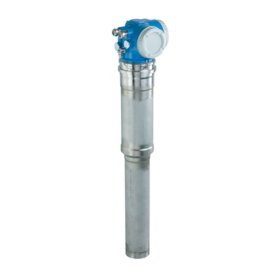
Gammapilot M FMG60
PROFIBUS PA
Radiometric measurement
These Instructions are Brief Operating Instructions; they are
not a substitute for the Operating Instructions pertaining to
the device.
For detailed information, refer to the Operating Instructions
and other documentation.
Available for all device versions via:
• Internet: www.endress.com/deviceviewer
• Smart phone/Tablet: Endress+Hauser Operations App
Solutions
Services
Advertisement
Table of Contents

Related Manuals for Endress+Hauser PROFIBUS PA


Summary of Contents for Endress+Hauser PROFIBUS PA
- Page 1 These Instructions are Brief Operating Instructions; they are not a substitute for the Operating Instructions pertaining to the device. For detailed information, refer to the Operating Instructions and other documentation. Available for all device versions via: • Internet: www.endress.com/deviceviewer • Smart phone/Tablet: Endress+Hauser Operations App...
- Page 2 Gammapilot M FMG60 PROFIBUS PA Order code: XXXXX-XXXXXX Ser. no.: XXXXXXXXXXXX Ext. ord. cd.: XXX.XXXX.XX Serial number www.endress.com/deviceviewer Endress+Hauser Operations App A0023555 Endress+Hauser...
- Page 3 Gammapilot M FMG60 PROFIBUS PA Gammapilot M - Quick guide Gammapilot M - Quick guide A0036818-EN Endress+Hauser...
-
Page 4: Table Of Contents
PROFIBUS PA cable specifications ........ -
Page 5: About This Document
Gammapilot M FMG60 PROFIBUS PA About this document About this document Symbols used 1.1.1 Safety symbols Symbol Meaning DANGER! DANGER This symbol alerts you to a dangerous situation. Failure to avoid this situation will result in serious or fatal injury. - Page 6 About this document Gammapilot M FMG60 PROFIBUS PA 1.1.4 Symbols for certain types of information Symbol Meaning Permitted Procedures, processes or actions that are permitted. Preferred Procedures, processes or actions that are preferred. Forbidden Procedures, processes or actions that are forbidden.
-
Page 7: Basic Safety Instructions
Gammapilot M FMG60 PROFIBUS PA Basic safety instructions Symbol Meaning Hazardous area Indicates the hazardous area. Safe area (non-hazardous area) Indicates the non-hazardous area. Basic safety instructions Requirements for the personnel The personnel must fulfill the following requirements for its tasks: ‣... -
Page 8: Radiation Protection
Basic safety instructions Gammapilot M FMG60 PROFIBUS PA connection values and safety instructions listed in this supplementary documentation must be observed. • Technical personnel must be suitably qualified and trained. • Comply with the metrological and safety-related requirements for the measuring point. -
Page 9: Workplace Safety
Gammapilot M FMG60 PROFIBUS PA Basic safety instructions Shielding Ensure the best possible shielding between the radiation source and yourself and all other persons. Effective shielding is provided by source containers (FQG60, FQG61/FQG62, FQG63, QG2000) and all high-density materials (lead, iron, concrete etc.). -
Page 10: Product Safety
It meets general safety standards and legal requirements. It also complies with the EC directives listed in the device-specific EC Declaration of Conformity. Endress+Hauser confirms this by affixing the CE mark to the device. Installation Incoming acceptance, product identification, transport, storage 3.1.1... -
Page 11: Installation Conditions
Gammapilot M FMG60 PROFIBUS PA Installation 3.1.4 Storage Pack the device so that it is protected against impact for storage and transport. The original packaging provides optimum protection. The permissible storage temperature is: • –40 to +50 °C (–40 to +122 °F) for devices with PVT scintillator •... - Page 12 Installation Gammapilot M FMG60 PROFIBUS PA Examples A0018074 Vertical cylinder; the Gammapilot M is mounted vertically with the detector head pointing downwards, the gamma ray is aligned to the measuring range. Cascading of multiple Gammapilot M devices; there is no gap between the measuring ranges...
- Page 13 Gammapilot M FMG60 PROFIBUS PA Installation 3.2.2 Installation conditions for point level detection Conditions • For point level detection, the Gammapilot M is generally mounted horizontally at the height of the desired level limit. • The angle of emission of the source container must be exactly aligned to the measuring range of the Gammapilot M.
- Page 14 • If only horizontal pipes are accessible, the path of the beam should also be arranged horizontally to minimize the influence of air bubbles and deposits. • The Endress+Hauser clamping device FHG61 or an equivalent clamping device should be used to secure the radiation source container and the Gammapilot M to the measuring tube.
-
Page 15: Water Cooling
Gammapilot M FMG60 PROFIBUS PA Installation A0018076 Vertical beam (90°) Diagonal beam (30°) Measurement section Sample point • To increase the accuracy of density measurements, the use of a collimator is recommended. The collimator screens the detector against environmental radiation. -
Page 16: Wiring
Wiring Gammapilot M FMG60 PROFIBUS PA Wiring Connection compartments The Gammapilot M has two connection compartments A0018082 Connection compartment 1 Connection compartment 2 Connection compartment 1 Connection compartment for: • Power supply • Signal output (depending on the device version) -
Page 17: Cable Entries
Gammapilot M FMG60 PROFIBUS PA Wiring • For cascade, 20 m (66 ft) per device • For Pt-100 2 m (6.6 ft). Temperature measurement should be performed as close as possible to density measurement. Cable entries The number and type of cable entries depend on the device version ordered. The following are possible: •... -
Page 18: Terminal Assignment
Wiring Gammapilot M FMG60 PROFIBUS PA Terminal assignment Connection compartment 1 A0018084 1 For the terminal assignment, see the table below Power supply: 90 to 253VAC, 18 to 35 VDC Connection compartment 2 SIM WP PT100 11 12 IN CASCADE OUT A0018085 ... - Page 19 Gammapilot M FMG60 PROFIBUS PA Wiring Terminal Meaning Grounding of the cable shield 1, 2 Power supply Connection Signal output, depending on communication version: compartment 2: • 4-20mA with HART 3, 4 • PROFIBUS PA Connection • FOUNDATION Fieldbus compartment 1: Depending on the device version ordered, the signal output is located in connection compartment 1 or 2 (see below).
-
Page 20: Profibus Pa Cable Specifications
Wiring Gammapilot M FMG60 PROFIBUS PA Connection compartment with terminals for Feature 30 of the ordering information: power supply wiring/output wiring Supply Signal voltage output Non-Ex; non-Ex Ex e; Ex ia Ex e; Ex e Ex d (XP); Ex d (XP) Ex d (XP);... -
Page 21: Supply Voltage
Gammapilot M FMG60 PROFIBUS PA Wiring Supply voltage All of the following voltages are terminal voltages directly at the device: Version Minimum terminal voltage Maximum terminal voltage Standard 32 V Ex ia (FISCO model) 17.5 V Ex ia (Entity concept) 24 V The current consumption is approx. -
Page 22: Wiring In Connection Compartment 1
Wiring Gammapilot M FMG60 PROFIBUS PA Wiring in connection compartment 1 CAUTION Note the following before connecting: ‣ If the device is used in hazardous areas, make sure to comply with national standards and the specifications in the Safety Instructions (XAs). The specified cable gland must be used. -
Page 23: Wiring In Connection Compartment 2
Gammapilot M FMG60 PROFIBUS PA Wiring Using a 3 mm Allen key, loosen the cover clamp for the connection compartment cover Unscrew the cover Push the power cable and (if required) the signal cable through the appropriate cable glands or cable entries... -
Page 24: Connecting The Remote Display And Operating Unit Fhx40
Wiring Gammapilot M FMG60 PROFIBUS PA SIM WP PT100 9 10 11 12 IN CASCADE OUT A0019827 Unscrew the cover Push the following cables through the corresponding cable glands or cable entries: signal cable (if the signal output is located in connection compartment 2), Pt100 cable... -
Page 25: Wiring For Cascade Mode
Gammapilot M FMG60 PROFIBUS PA Wiring A0018089 Gammapilot M FMG60 Cable of the display and operating unit FHX40 For some Dust-Ex versions of the Gammapilot M, the FHX40 connector is protected by a metal sleeve: A0018090 Loosen the sleeve with an Allen key and remove it... -
Page 26: Post-Connection Check
Operation Gammapilot M FMG60 PROFIBUS PA 4.11 Post-connection check After wiring the device, carry out the following checks: • Is the protective ground connected? • Is the potential matching line connected? • Is the terminal assignment correct? • Are the cable glands and dummy plugs tight? •... - Page 27 LOCK_SYMBOL This lock symbol is displayed when the device is locked, i.e. if no entries are possible. COM_SYMBOL This communication symbol is displayed when data transmission via HART, PROFIBUS PA or FOUNDATION Fieldbus, for example, is in progress. SIMULATION_SWITCH_ENABLE This communication symbol is displayed when simulation in FOUNDATION Fieldbus is enabled via the DIP switch.
- Page 28 Operation Gammapilot M FMG60 PROFIBUS PA Operating key(s) Meaning Navigate to the left within a function group Navigate to the right within a function group, confirmation Contrast settings of the LCD Hardware locking/unlocking After locking the hardware, operation via the display and communication is not possible! The hardware can only be unlocked via the display.
-
Page 29: Commissioning
Gammapilot M FMG60 PROFIBUS PA Commissioning • The alphabetic character indicates the current measurement mode of the Gammapilot M: – L: Level – S: Switch – D: Density – C: Concentration – *: no measurement mode selected yet • The first numeric character identifies the function group: –... -
Page 30: Calibration: Overview
Commissioning Gammapilot M FMG60 PROFIBUS PA Calibration: overview Power up instrument "Switching on the device" Basic setup "Basic setup" Calibration for density and concentration measurements “Calibration for density and concentration measurements“ Calibration for level measurement Calibration for density and point level detection measurements/temp. -
Page 31: Function Check
Gammapilot M FMG60 PROFIBUS PA Commissioning Function check Ensure that the post-installation check and post-connection check were carried out before the measuring point was commissioned. • "Post-installation check" checklist (see "Post-installation check" section) • "Post-connection check" checklist (see "Post-connection check" section) Switching on the device Error messages A165 "Electronics defect"... -
Page 32: Basic Setup
Commissioning Gammapilot M FMG60 PROFIBUS PA The measured value screen then appears. The basic setup can now be performed. Press to switch to the group selection: Press again to enter the first function of the "Basic setup" function group Basic setup 6.4.1... - Page 33 Only one Gammapilot M is required for measuring ranges up to 2 m (6.6 ft) For larger measuring ranges, any number of Gammapilot M devices can be interconnected (cascade mode). The devices are defined by software settings as: Master Slave(s) or End slave 4 to 20 mA HART; PROFIBUS PA; FOUNDATION Fieldbus Endress+Hauser...
- Page 34 Commissioning Gammapilot M FMG60 PROFIBUS PA Options/display: • Stand alone: This option is selected if the Gammapilot M is used as a single, standalone device. • Master: This option is selected if the Gammapilot M is located at the beginning of a cascade chain.
- Page 35 Gammapilot M FMG60 PROFIBUS PA Commissioning A0018108 Level measurement (continuous) Point level detection Density measurement (with temperature compensation if required) Concentration measurement (density measurement followed by linearization) ρ Density Concentration 6.4.6 "Density unit" (*06) Local display Density unit *06 ✓ g/cm lb/gal This function is needed for density and concentration measurements only.
- Page 36 Commissioning Gammapilot M FMG60 PROFIBUS PA Further options: • g/cm • g/l • lb/gal; [1g/cm = 8.345 lb/gal] • lb/ft ; [1g/cm = 62.428 lb/ft • °Brix; [1°Brix =270 (1 - 1/x)] • °Baumé; [1°Baumé = 144.3 (1 - 1/x)] •...
- Page 37 Gammapilot M FMG60 PROFIBUS PA Commissioning 6.4.10 "Pipe diameter" (*0A) Local display Pipe diam. *0A 200 mm This function is needed for density and concentration measurements only. It is used to specify the irradiated measuring path L. With standard installation, this value is identical to the pipe inner diameter D .
-
Page 38: Calibration For Level Measurement And Point Level Detection
Commissioning Gammapilot M FMG60 PROFIBUS PA This function is used to specify the output damping time τ (in seconds). A change in the measured value is attenuated by this time. After a change in the level or density it takes 5 x τ... - Page 39 Gammapilot M FMG60 PROFIBUS PA Commissioning Calibration points for level measurement A0018111 Background calibration Full calibration Empty calibration Background calibration Free calibration refers to the following situation: • The radiation is switched off • The vessel is filled as much as possible (ideally 100%) within the measuring range The background calibration is necessary in order to register the natural background radiation at the mounting position of the Gammapilot M.
- Page 40 Commissioning Gammapilot M FMG60 PROFIBUS PA Empty calibration Free calibration refers to the following situation: • The radiation is switched on • The vessel is emptied as much as possible (ideally 0%, at least 40%) within the measuring range. Calibration points for point level detection...
- Page 41 Gammapilot M (e.g. because the vessel cannot be sufficiently filled or emptied), this calibration point must be entered manually. This means that both the level and the associated pulse rate must be entered directly. Please contact Endress+Hauser Service for any questions regarding the calculation of the pulse rate.
- Page 42 Commissioning Gammapilot M FMG60 PROFIBUS PA backgr. calibr. avg. pulse rate bgr. pulse rate 0: stop/ edit 1: start -1: not calibrated A0037161-EN "Background calibration" (*10) Local display Backgr. cal. *10 Stop/edit Start This function is used to start the background calibration Options: •...
- Page 43 Gammapilot M FMG60 PROFIBUS PA Commissioning "E" A0018118 When the value is sufficiently stable users can quit the function by pressing . After this, the Gammapilot M changes to the "Background calibration" (*10) function. Here the "Stop/edit" option must be selected to stop the integration. The value is then automatically transmitted to the "Background pulse rate"...
- Page 44 Commissioning Gammapilot M FMG60 PROFIBUS PA full calibr. value full calibration avg. [c/s] 0: stop / edit puls rate -1: not target value 1: start calibrated at calibr. point Group next point calibr. point selection 0: no 0: full/covered 1: yes 1: empty/free empty calibr.
- Page 45 Gammapilot M FMG60 PROFIBUS PA Commissioning "Value full" (*14) / "Value empty" (*17) Local display Value full *14 100% Local display Value empty *17 These functions are needed for level measurements only. They are used to specify the level at which the full or empty calibration is performed.
- Page 46 Commissioning Gammapilot M FMG60 PROFIBUS PA "Avg. pulse rate" (*11) Local display Avg. pulse rate *11 2548 cps The average (integrated) pulse rate is displayed in this function (after the selection of "Start" in the previous function). Initially, this value fluctuates (because of the decay statistics), but reaches an average value over time due to integration.
-
Page 47: Calibration For Density And Concentration Measurements
6.5.4 Additional settings After the basic setup, the Gammapilot M outputs the measured value via the PROFIBUS PA interface. Many additional functions are available for optimizing the measuring point and can be configured as required. For a detailed description of all the device functions, see BA00287F/00/EN, "Gammapilot M - Description of Device Functions", or the CD-ROM... - Page 48 Commissioning Gammapilot M FMG60 PROFIBUS PA Calibration points for density and concentration measurements Function of the calibration points In addition to the length of the irradiated measuring path, the Gammapilot M also needs the following two parameters for density and concentration measurements: •...
- Page 49 Gammapilot M FMG60 PROFIBUS PA Commissioning One-point calibration A one-point calibration can be performed if a two-point calibration is not possible. This means that apart from the background calibration only one additional calibration point is used. This calibration point should be as close as possible to the operating point. Densities in the proximity of this calibration point are measured quite accurately, but the accuracy can decrease as the distance from the calibration point increases.
- Page 50 Commissioning Gammapilot M FMG60 PROFIBUS PA 6.6.2 Background calibration Excerpt from the operating menu The following excerpt from the operating menu illustrates the entries to be made for background calibration. The individual functions are explained in detail in the sections that follow.
- Page 51 Gammapilot M FMG60 PROFIBUS PA Commissioning The average pulse rate is displayed in this function. Initially, this value fluctuates (because of the decay statistics), but reaches an average value over time due to integration. The longer the averaging is performed, the lower the fluctuations.
- Page 52 Commissioning Gammapilot M FMG60 PROFIBUS PA 6.6.3 Calibration points The following excerpt from the operating menu illustrates the procedure for entering the density calibration points. The individual functions are explained in detail in the sections that follow. The functions are only accessible once the background calibration has been performed.
- Page 53 Gammapilot M FMG60 PROFIBUS PA Commissioning "Calibration point" (*1A) Local display Calibration point *1A ✓ 1 This function is used to select the calibration point which will be entered. Further options: • "1" to "9": calibration points for various densities •...
- Page 54 Commissioning Gammapilot M FMG60 PROFIBUS PA an average value over time due to integration. The longer the averaging is performed, the lower the fluctuations. "E" A0018118 When the value is sufficiently stable users can quit the function by pressing . After this, the Gammapilot M changes to the "Calibration"...
- Page 55 Gammapilot M FMG60 PROFIBUS PA Commissioning "Density value" (*1C) Local display Density value *1C 0.9963 g/cm3 This function is used to specify the density of the calibration point. The value must be determined using a sample in the laboratory. The temperature effect must be taken into account when entering the density value. The density entered must refer to the temperature at which the pulse rate has been determined.
-
Page 56: Density Measurement/Temperature-Compensated
6.6.5 Additional settings After the basic setup, the Gammapilot M outputs the measured value via the PROFIBUS PA interface. Many additional functions are available for optimizing the measuring point and can be configured as required. For a detailed description of all the device functions, see BA00287F/00/EN, "Gammapilot M - Description of Device Functions", or the CD-ROM... -
Page 57: Gammagraphy Detection
Gammapilot M FMG60 PROFIBUS PA Commissioning compensation" section in BA00287F/00/EN "Gammapilot M - Description of Device Functions"). Gammagraphy detection See the "Gammagraphy" section of BA00287F/00/EN "Gammapilot M - Description of Device Functions". Endress+Hauser... - Page 60 *71402951* 71402951 www.addresses.endress.com...