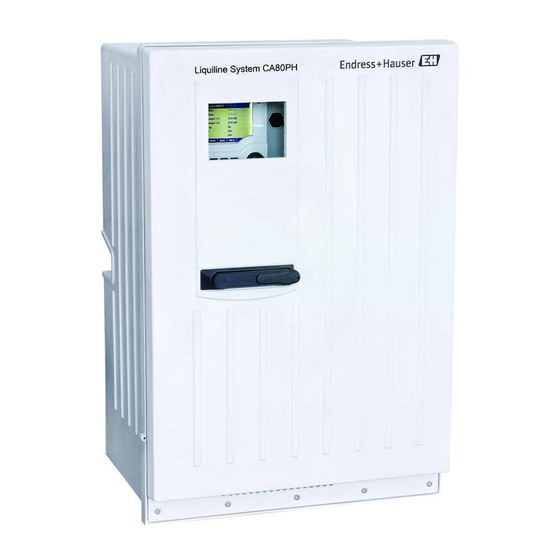
Endress+Hauser Liquiline System CA80PH Brief Operating Instructions
Colorimetric analyzer for orthophosphate
Hide thumbs
Also See for Liquiline System CA80PH:
- Operating instructions manual (208 pages) ,
- Operating instructions manual (180 pages) ,
- Brief operating instructions (48 pages)
Table of Contents
Advertisement
Quick Links
KA01186C/07/EN/05.20
71468053
2020-02-15
Products
Brief Operating Instructions
Liquiline System CA80PH
Colorimetric analyzer for orthophosphate
These instructions are Brief Operating Instructions; they are
not a substitute for the Operating Instructions pertaining to
the device.
Detailed information on the device can be found in the
Operating Instructions and in the other documentation
available at:
• www.endress.com/device-viewer
• Smart phone/tablet: Endress+Hauser Operations App
Solutions
Services
Advertisement
Table of Contents

Related Manuals for Endress+Hauser Liquiline System CA80PH


Summary of Contents for Endress+Hauser Liquiline System CA80PH
- Page 1 These instructions are Brief Operating Instructions; they are not a substitute for the Operating Instructions pertaining to the device. Detailed information on the device can be found in the Operating Instructions and in the other documentation available at: • www.endress.com/device-viewer • Smart phone/tablet: Endress+Hauser Operations App...
- Page 2 Liquiline System CA80PH Order code: XXXXX-XXXXXX Ser. no.: XXXXXXXXXXXX Ext. ord. cd.: XXX.XXXX.XX Serial number www.endress.com/deviceviewer Endress+Hauser Operations App A0040778 Endress+Hauser...
-
Page 3: Table Of Contents
Liquiline System CA80PH Table of contents Table of contents About this document ............. . 4 Warnings . -
Page 4: About This Document
About this document Liquiline System CA80PH About this document Warnings Structure of information Meaning This symbol alerts you to a dangerous situation. DANGER Failure to avoid the dangerous situation will result in a fatal or serious injury. Causes (/consequences) If necessary, Consequences of non- compliance (if applicable) ‣... -
Page 5: Symbols On The Device
Warning: Risk of injury from rotating cogwheels Documentation The following instructions complement these Brief Operating Instructions and are available on the product pages on the Internet: • Operating Instructions Liquiline System CA80PH • Device description • Commissioning • Operation • Software description (excluding sensor menus; these are described in a separate manual - see below) •... -
Page 6: Basic Safety Instructions
Designated use The Liquiline System CA80PH is a wet-chemical analyzer for the almost continuous determination of the concentration of orthophosphate in liquid media. The analyzer is designed for use in the following applications: •... -
Page 7: Product Safety
Liquiline System CA80PH Basic safety instructions Ensure that electrical cables and hose connections are undamaged. Do not operate damaged products, and protect them against unintentional operation. Label damaged products as defective. During operation: If faults cannot be rectified: products must be taken out of service and protected against unintentional operation. -
Page 8: Incoming Acceptance And Product Identification
Incoming acceptance and product identification Liquiline System CA80PH Incoming acceptance and product identification Incoming acceptance Verify that the packaging is undamaged. Notify the supplier of any damage to the packaging. Keep the damaged packaging until the issue has been resolved. -
Page 9: Scope Of Delivery
Liquiline System CA80PH Incoming acceptance and product identification 3.2.2 Product identification Product page www.endress.com/ca80ph Interpreting the order code The order code and serial number of your product can be found in the following locations: • On the nameplate • In the delivery papers Obtaining information on the product Go to www.endress.com. -
Page 10: Installation
Installation Liquiline System CA80PH 3.4.2 cCSAus The product meets the requirements as per "CLASS 2252 06 - Process Control Equipment" and "CLASS 2252 86 - Process Control Equipment". It is tested to Canada and USA standards: CAN/ CSA-C22.2 No. 61010-1-12 UL Std. No. 61010-1 (3 Edition). - Page 11 Liquiline System CA80PH Installation 417 (16.42) 530 (20.87) A0030419 2 Liquiline System CA80 open version, dimensions in mm (in) Endress+Hauser...
- Page 12 Installation Liquiline System CA80PH 654 (25.74) A0028821 3 Liquiline System CA80 with base, dimensions in mm (in) Endress+Hauser...
- Page 13 Liquiline System CA80PH Installation 1800 (70.9) 8 (0.31) A0041592 4 Post (accessory) for "Outdoor" version, dimensions in mm (inch) 4.1.2 Mounting location Note the following when erecting the device: ‣ If mounting on a wall, make sure that the wall has sufficient load-bearing capacity and is fully perpendicular.
- Page 14 Installation Liquiline System CA80PH 4.1.3 Spacing requirements when mounting Spacing required for installing analyzer ≥330(12.99) ≤116 ° A0036774 A0036775 5 Minimum spacing required for mounting. 6 Maximum opening angle Engineering unit mm (in). Spacing required for installing wall-mount version Ø...
-
Page 15: Mounting The Analyzer On A Wall
Liquiline System CA80PH Installation Mounting the analyzer on a wall CAUTION Incorrect installation can cause injury and damage the device ‣ If mounting on a wall, check that the analyzer is fully hooked into the wall holder unit at the top and bottom, and secure the analyzer to the upper wall holder unit using the securing screw. -
Page 16: Installing Version With Analyzer Stand
Installation Liquiline System CA80PH Hook the analyzer into the wall holder unit. Secure the two top parts of the wall holder unit with the screw supplied. Installing version with analyzer stand CAUTION Incorrect installation can cause injury and damage the device ‣... - Page 17 Liquiline System CA80PH Installation A0036785 11 Securing the base Screw the base to the ground. With 2 people, lift the analyzer and fit it on the base. Use the recessed grips. Secure the base to the analyzer using the 6 screws supplied.
-
Page 18: Outdoor" Version: Mounting On A Post
Installation Liquiline System CA80PH "Outdoor" version: mounting on a post 4.4.1 Erecting the post 4 x 12 (0.47) 250 (9.84) A0041437 12 Foundation plan, dimensions in mm (in) When installing outdoors, consideration must be given to providing correct protection against lightning. - Page 19 Liquiline System CA80PH Installation 4.4.2 Tool required for post mounting The following tools, which must be provided by the customer at the point of installation, are required to mount the analyzer on the post: • Open-end wrench, 17mm AF (for post retainer) •...
- Page 20 Installation Liquiline System CA80PH 4.4.3 Mounting analyzer on the post A0041425 A0041426 13 Analyzer mounted on post (from front) 14 Analyzer mounted on post (from behind) Fit the clamp of the post retainer on the retaining rods and post using the nuts.
- Page 21 Liquiline System CA80PH Installation Fit the counterparts and fasten the post retainer using spring washers and nuts. Mount the wall holder unit (included in the delivery with the analyzer) on the post retainer. Endress+Hauser...
- Page 22 Installation Liquiline System CA80PH Insert the spacer. Screw the suspension bracket of the wall holder unit (included in the delivery with the analyzer) onto the analyzer. Endress+Hauser...
-
Page 23: Post-Installation Check
Liquiline System CA80PH Electrical connection Hook in the analyzer. Fix the upper wall holder unit in place with the screw provided. Post-installation check After mounting, check all the connections to ensure they are secure. Electrical connection WARNING Device is live! Incorrect connection may result in injury or death! ‣... -
Page 24: Connection Conditions
Electrical connection Liquiline System CA80PH ‣ Before establishing the electrical connection, verify that the pre-installed power cable meets the local national electrical safety specifications. Connection conditions 5.1.1 Cable types Power supply cable Power supply cable with safety plug A power supply cable is not supplied for the Cable length 4.3 m (14.1 ft) - Page 25 Liquiline System CA80PH Electrical connection Connection of analog inputs and outputs, Memosens sensors or digital fieldbuses Remove the bottle tray: Lift up the recessed grip slightly and pull it towards the front. Remove the cover that is hooked into place.
- Page 26 Electrical connection Liquiline System CA80PH Fold out the carrier board towards the front . For convenience of handling, hook the carrier board onto the locking plate. 6 x Ph2 Release the 6 screws on the electronics compartment cover using a Phillips-head screwdriver and fold out the cover towards the front.
- Page 27 Liquiline System CA80PH Electrical connection Only for the "Outdoor" version Guide the cable of the heated waste hose through the cable gland indicated. Guide the power supply cable, which is provided by the customer at the installation location, through the cable gland indicated.
- Page 28 Electrical connection Liquiline System CA80PH To access the electronics compartment, proceed as described in the "Routing the cables" section (→ 24). Guide the 24V connecting cable from below through the cable gland on the inner rear panel of the device and feed it up into the electronics compartment.
- Page 29 Liquiline System CA80PH Electrical connection 5.2.3 "Outdoor" version: Connecting power supply and hose heater The power supply cable is not included with the delivery and must be provided by the customer. Guide the power supply cable and the cable of the hose heater from below through the cable gland on the inner rear panel of the device and feed them up into the electronics compartment (→...
-
Page 30: Connecting Sample Preparation
Electrical connection Liquiline System CA80PH Connecting sample preparation 5.3.1 Connecting the optional cleaning valve of Liquiline System CAT810 Disconnect the mains plug. To fold out the carrier board towards the front, proceed as described in the "Routing the cables" section . - Page 31 Liquiline System CA80PH Electrical connection 5.3.2 Connecting the optional hose heater and communication between the CAT820/ CAT860 and the analyzer Only use terminated original cables where possible. The sensor cable, fieldbus cable and Ethernet cable must be shielded cables. Cable sample (does not necessarily correspond to the original cable supplied) ...
-
Page 32: Ensuring The Degree Of Protection
Electrical connection Liquiline System CA80PH Remove the protective cover in the upper right-hand corner. A0028925 Route the cable in the housing in such a way that the exposed cable shield fits into one of the cable clamps and the cable cores can be easily routed as far as the plug-in terminals. -
Page 33: Post-Connection Check
Liquiline System CA80PH Electrical connection Individual types of protection permitted for this product (impermeability (IP), electrical safety, EMC interference immunity, Ex protection) can no longer be guaranteed if, for example : • Covers are left off • Different power units to the ones supplied are used •... -
Page 34: Operation Options
Operation options Liquiline System CA80PH Operation options Structure and function of the operating menu Menu/Language English Čeština Nederlands Français Deutsch Italiano Polski A0040682 A0036773 23 Display (example) 22 Display (example) Menu path and/or device designation Soft key (press function) - Page 35 Liquiline System CA80PH Commissioning CAUTION Activities while the analyzer is in operation Risk of injury and infection from medium or reagents , reagents or cleaner! ‣ Before you release any hoses, make sure that no actions, such as the pumping of sample, are currently running or are due to start shortly.
- Page 36 Commissioning Liquiline System CA80PH optional dilution A0041466 25 Liquiline System CA80PH (blue method), single-channel device Cleaner Photometer/measuring cell Standard 1 Sample Reagent RK 2, 3, 4, 7 Dispensers Reagent RB Outlet Outlet Sample collecting vessel Cuvette T-piece Endress+Hauser...
- Page 37 Liquiline System CA80PH Commissioning optional dilution A0041467 26 Liquiline System CA80PH (blue method), two-channel device Cleaner Photometer/measuring cell Standard 1 Sample Reagent RK 2, 3, 4, 7 Dispensers Reagent RB Outlet Outlet Sample collecting vessel Cuvette T-piece Endress+Hauser...
- Page 38 Commissioning Liquiline System CA80PH optional dilution A0033657 27 Liquiline System CA80PH (blue method), self-priming Cleaner Photometer/measuring cell Standard 1 Sample Reagent RK 2, 3, 4, 7 Dispensers Reagent RB Outlet Outlet Cuvette T-piece Endress+Hauser...
- Page 39 Liquiline System CA80PH Commissioning optional dilution A0041468 28 Liquiline System CA80PH (molybdate-vanadate method), single-channel device Standard 1 Sample Reagent RK 2, 3, 7 Dispensers Outlet Outlet Cuvette Sample collecting vessel Photometer/measuring cell T-piece Endress+Hauser...
- Page 40 Commissioning Liquiline System CA80PH optional dilution A0041469 29 Liquiline System CA80PH (molybdate-vanadate method), two-channel device Standard 1 Sample Reagent RK 2, 3, 7 Dispensers Outlet Outlet Cuvette Sample collecting vessel Photometer/measuring cell T-piece optional dilution A0033658 30 Liquiline System CA80PH (molybdate-vanadate method), self-priming...
-
Page 41: Function Check
Liquiline System CA80PH Commissioning Reagent RK 2, 3, 7 Dispensers Outlet Outlet Photometer/measuring cell Cuvette T-piece 7.1.2 Connecting the sample inlet hose Ensure a constant and sufficient supply of sample at the installation location. Connect the liquid-bearing hoses of the sample supply system. -
Page 42: Switching On The Measuring Device
Commissioning Liquiline System CA80PH Instrument status and specifications ‣ Are the hoses free from damage on the outside? Visual inspection of the liquid-bearing lines ‣ Check the hose connections using the hose connection diagram. ‣ Is the suction line connected to the sample collector (if present)? ‣... - Page 43 Liquiline System CA80PH Commissioning If you wish to configure your most important input and output parameters in the Basic setup analyzer : ‣ Configure the current inputs, relays, limit switches, cleaning cycles and device diagnostics with the following submenus. Endress+Hauser...
- Page 44 *71468053* 71468053 www.addresses.endress.com...