Life Fitness Axiom Series Assembly Instructions Manual
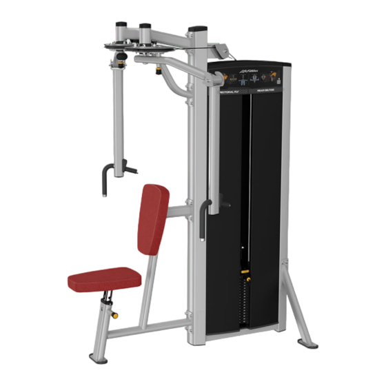
Pectoral fly / rear deltoid
Hide thumbs
Also See for Axiom Series:
- Owner's manual (48 pages) ,
- Assembly instructions manual (44 pages) ,
- Assembly instructions manual (42 pages)

Related Manuals for Life Fitness Axiom Series


Summary of Contents for Life Fitness Axiom Series
- Page 1 Axiom Series Pectoral Fly / Rear Deltoid OP-FLY Assembly Instructions 1015205-0001 REV AC...
- Page 3 Latin America and Caribbean* Spain Hong Kong Life Fitness, LLC Life Fitness IBERIA Life Fitness Asia Pacific LTD Columbia Centre III C/Frederic Mompou 5,1º1ª 32/F, Global Trade Square 9525 Bryn Mawr Avenue 08960 Sant Just Desvern Barcelona 21 Wong Chuk Hang Road Rosemont, IL 60018 U.S.A.
- Page 4 User and Service Documents Link https://lifefitness9512.zendesk.com/hc/en-us https://www.lftechsupport.com/web/document-library/documents Additional information is available online using the links above. أ علاه إل ر إبط باستخدإم إ لإ ن تر نت على إضافية معلومات تتوفر 点击上面的链接可在线获取更多信息。 Flere oplysninger er tilgængelige online gennem linket ovenfor. Bijkomende informatie is online beschikbaar via bovenstaande link.
-
Page 5: Table Of Contents
2XL Corporation. PureGreen 24 is a trademark of Pure Green. © Copyright 2021, Life Fitness, LLC. All Rights Reserved. Life Fitness, Hammer Strength, Cybex, ICG and SCIFIT are registered trademarks of Life Fitness, LLC and its affiliated companies and subsidiaries. Brunswick and related trademarks used under license from Brunswick Corporation. -
Page 6: Safety Information
• DO NOT use or permit use of any equipment that is damaged and/or has worn or broken parts. For all Life Fitness Family of Brands equipment, use only replacement parts supplied by Life Fitness Family of Brands. - Page 7 Life Fitness Family of Brands will provide service and maintenance training at our corporate facility upon request or in the field if proper arrangements are made. • Before use, examine all accessories approved for use with the Life Fitness Family of Brands equipment for damage or wear.
-
Page 8: Product Labels
Product Labels General Warning Serial Number Page 6 of 34... -
Page 9: Label Locations
Label Locations Item Description Qty. General Warning Serial Number Page 7 of 34... -
Page 10: Assembly
2. Assembly Component and Hardware List Tower Components Item Description Qty. Tower Frame Guide Rod Increment Weight Guide Rod Rear Shroud Weight Stack Label Tube Cap Top Cap Tower Hardware Kit Item Description Qty. Tower Hardware Kit, OP-FLY Hole Plug, 8.7 mm Shroud Retainer Grommet Screw, 8 x ¾", Phillips... - Page 11 Tower Hardware Kit Optional: Front Shroud Kit Components Item Description Qty. Front Shroud, Left Front Shroud, Right Bottom Cap Optional: Front Shroud Kit Hardware Kit Item Description Qty. Front Shroud Hardware Kit Screw, M4.2 x 0.7, Phillips Screw, M10 x 1.5, 20mm Washer, Flat 3/8"...
- Page 12 Components Item Description Qty. Support Leg, Front Support Leg, Rear Seat Frame Assembly Seat Post Assembly Overhead Frame Assembly Head Plate Pulley Bracket Front Cap Head Plate Assembly Increment Weight Assembly Multilingual Label Sheet Upper Work Arm Assembly, Left Upper Work Arm Assembly, Right Cam Assembly, Left Cam Assembly, Right Cable...
-
Page 13: Tools Required
Item Description Qty. Cotter Pin Cable Retainer Increment Weight Cap, LBS Increment Weight Cap, KG Hole Plug, 1" Spacer, Internal .653 Cable Retainer Cover Plate Pivot Shaft Threaded Cap Pulley, 3.5" OD Hardware Kit Tools Required • 7/16" Wrench • 10 mm Wrench •... -
Page 14: Assembly Procedure
Assembly Procedure Assemble Frame Components 1. Install screws and washers securing the front support leg to the tower frame using an 8 mm Allen wrench. Item Description Qty. Support Leg, Front Washer, Flat 3/8" Screw, M10 x 1.5, 25 mm Tighten hardware to 20-25 ft-lb (27.1-33.9 Nm). - Page 15 5. Install screws securing seat glide bushing to main frame using a Phillips screwdriver. Item Description Qty. Seat Post Assembly Seat Glide Bushing Seat Frame Screw, M5 x 10, Phillips Tighten hardware to 30-39 in-lb (3.4-4.4 Nm). 6. Install screws and washers securing the overhead frame assembly to the tower frame using an 8mm Allen wrench. Item Description Qty.
- Page 16 Assemble Tower 1. Install the increment weight bumper to the bottom plate of the tower frame. Item Description Qty. Increment Weight Bumper Tower Frame 2. Slide increment weight guide rods through the top of the tower frame and down through the clips in the increment weight.
- Page 17 4. Install nuts and washers securing the increment weight guide rods to the top plate of the tower frame using a 7/16" wrench. Item Description Qty. Nut, ¼" Nylock Washer, Flat ¼" ID Increment Weight Guide Rod Tighten hardware to 16-20 in-lb (1.8-2.2 Nm). 5.
- Page 18 7. NOTE: OPTIONAL: If your product does not include front shrouds, skip this step. Install screws and washers securing the bottom cap to the bottom of the tower frame using an 8mm Allen wrench. Item Description Qty. Bottom Cap Screw, M10 x 1.5, 20mm Washer, Flat 3/8"...
- Page 19 9. NOTE: OPTIONAL: If your product does not include front shrouds, skip this step. Install screws and shroud retainer grommets into the side tubes of the tower frame using a Phillips screwdriver. Item Description Qty. Grommet, Shroud Retainer Screw, M4.2 x 0.7, Phillips Tighten hardware to 10-13 in-lb (1.1-1.5 Nm).
- Page 20 12. Place guide rods with weight stack cushions into the holes at the bottom of the tower frame. Item Description Qty. Guide Rod Weight Stack Cushion 13. Lean guide rods outwards and slide weight stack down guide rods onto weight stack cushions. Slide head plate assembly down guide rods and onto weight stack.
- Page 21 15. Select the LBS (7.5) or KG (3.75) option of the increment weight cap. Press increment weight cap into the head plate assembly. Item Description Qty. Increment Weight Cap Head Plate Assembly 16. Thread head plate pulley bracket through the jam nut and into the head plate bayonet. See Cable Handling Guide for details.
- Page 22 17. Select either the LBS or KG weight stack label. Remove backing from label and apply to weight stack. NOTE: One weight stack label sheet, LBS or KG, is used for both weight stacks. Item Description Qty. Weight Stack Label Weight Stack 18.
- Page 23 22. Select the appropriate language from the multilingual label sheet. Remove backing from multilingual label and apply to the left and right slots in the front cap. Item Description Qty. Multilingual Label Front Cap Install Work Arms 1. Slide left cam assembly and spacer onto the shaft of the left upper work arm assembly. Make sure the detent pin on the work arm assembly is engaged in a detent position.
- Page 24 5. Repeat Steps 1-4 to install the right upper work arm assembly 6. Route one end of the cable into the right cam assembly. 7. Install cable retainer securing the cable to the right cam assembly. 8. Install screws, washers, and locknuts securing the cable retainer cover plate to right cam assembly using an 8mm Allen wrench and a 17mm wrench.
- Page 25 9. Route cable from the right cam assembly through the pulley weldment on the rear side of the tower frame and down over the pulley located below the top cap. Route cable back up over the pulley located below the top cap on the front side of the tower frame and through the pulley weldment to the left cam assembly.
- Page 26 12. Install screws, washers, and locknuts securing the cable retainer cover plate to left cam assembly using an 8mm Allen wrench and a 17mm wrench. Item Description Qty. Cable Cam Assembly, Left Cable Retainer Cable Retainer Cover Plate Screw, M10 x 1.5, 50mm Washer, Flat 3/8"...
- Page 27 15. Install screws, washers, and pivot shaft securing the left lower work arm assembly to the left upper work arm assembly using a 7mm Allen wrench. Item Description Qty. Lower Work Arm Assembly, Left Upper Work Arm Assembly, Left Pivot Shaft Washer, .375"...
- Page 28 Install Seat and Back Pads 1. Install screws and washers securing the seat pad to the seat frame assembly using an 8mm Allen wrench. Item Description Qty. Seat Pad Washer, Flat 3/8" Screw, M10 x 1.5, 30mm Tighten hardware to 40-50 in-lb (4.5-5.6 Nm). 2.
-
Page 29: Product Information
3. Product Information Specifications Machine Weight: 543 lbs. 246 kg. Size (L x W x H): in. = 61 x 75 x 81 cm = 155 x 191 x 206 Live Area (L x W x H): in. = 97 x 99 x 93 cm = 246 x 251 x 236 Max User Weight: 300 lbs. -
Page 30: Cable Handling Guide
WARNING: Use of non certified “techs” note: Service warranties may be void if a non-Life Fitness-certified technician performs service work. Replacement of any strength cables should be performed by a Life Fitness certified technician. -
Page 31: Tensioning Cable
Tensioning Cable Cable should have enough tension so it stays seated into the pulley but not so tight that it pulls the head plate off the weight plate below it. 1. If the head plate has lifted, loosen the jam nuts at the terminations and loosen the threaded plugs a half turn until the head plate comes to rest on the weight plate below. -
Page 32: Strength Cable Wear Guide
Strength Cable Wear Guide Replace cable at first sign of any of the following: FRACTURES: Casing can crack or fracture under strains during use. Any crack in the casing merits cable replacement even if no wire rope is exposed. Be especially observant for fractures near the components on the cable assembly - IE. -
Page 33: Bolt To Floor Guide Introduction
5. Bolt to Floor Guide Introduction Life Fitness Family of Brands designs its products to be stable when used as designed. Because strength training is dynamic, we cannot predict how users will ultimately use the products in all circumstances. Therefore, Life Fitness Family of Brands recommends that strength training equipment be secured to a solid, level surface to stabilize and eliminate rocking or tipping over. -
Page 34: Anchor Types
3000psi (20 N/mm2) beyond anchor length Pullout Force Life Fitness specifies Hilti ™ static and dynamic anchors. According to the anchor manufacturer, the recommended design pullout force (in tension) for the specified anchors, when properly installed in cracked concrete, is provided in the side table. -
Page 35: Static Anchor Procedure
Static Anchor Procedure CAUTION: If it is possible that the length of your bolt will not provide the minimum requirement of 2.5” (63.5mm) of engagement, a longer anchor should be used. 1. Place unit into position to be mounted and cycle unit to set stance. 2. -
Page 36: Foot Dimensions
Foot Dimensions Use below image to determine foot specifications. Page 34 of 34...