
Related Manuals for JLG R4045


Summary of Contents for JLG R4045
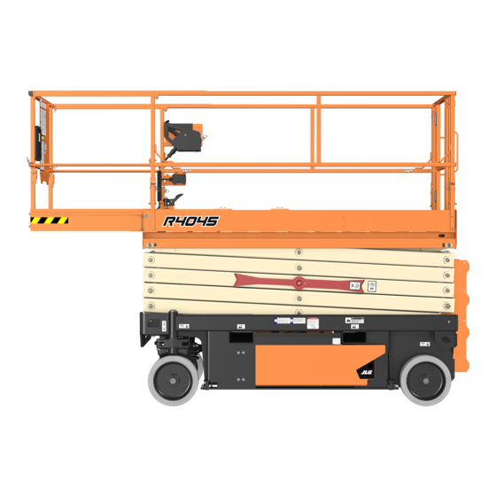
- Page 1 Operation and Safety Manual Original Instructions - Keep this manual with the machine at all times. Model R4045 PVC 2010 ANSI AS/NZS GB 31215942 September 1, 2020 - Rev A ®...
- Page 2 WARNING Operating, servicing and maintaining this vehicle or equipment can expose you to chemicals including engine exhaust, carbon monoxide, phthalates, and lead, which are known to the State of California to cause cancer and birth defects or other reproductive harm. To minimize exposure, avoid breathing exhaust, do not idle the engine except as necessary, service your vehicle or equipment in a well-ventilated area and wear gloves or wash your hands frequently when servicing.
- Page 3 The purpose of this manual is to provide owners, users, operators, lessors, and lessees with the precautions and operating proce- dures essential for the safe and proper machine operation for its intended purpose. Due to continuous product improvements, JLG Industries, Inc. reserves the right to make specification changes without prior noti- fication. Contact JLG Industries, Inc. for updated information.
- Page 4 SAFETY ALERT SYMBOLS AND SAFETY SIGNAL WORDS SAFETY ALERT SYMBOLS AND SAFETY SIGNAL WORDS THIS IS THE SAFETY ALERT SYMBOL. IT IS USED TO ALERT YOU TO THE POTEN- TIAL PERSONAL INJURY HAZARDS. OBEY ALL SAFETY MESSAGES THAT FOLLOW THIS SYMBOL TO AVOID POSSIBLE INJURY OR DEATH. INDICATES AN IMMINENTLY HAZARDOUS SITUATION.
- Page 5 NOTICE • Questions Regarding uct Modifications Product Safety JLG INDUSTRIES, INC. SENDS SAFETY RELATED BULLETINS TO THE OWNER OF RECORD OF THIS MACHINE. CONTACT JLG INDUSTRIES, INC. TO ENSURE THAT Contact: THE CURRENT OWNER RECORDS ARE UPDATED AND ACCURATE. Product Safety and Reliability Department JLG Industries, Inc.
- Page 6 REVISION LOG REVISION LOG Original Issue A - September 1, 2020 31215942...
-
Page 7: Table Of Contents
TABLE OF CONTENTS SECTION - 1 - SAFETY PRECAUTIONS PRE-START INSPECTION ........2-4 WALK-AROUND INSPECTION . - Page 8 TABLE OF CONTENTS Lift/Drive Select Switch .......3-10 3.14 MACHINE LIFTING AND TIE DOWN ..... .3-23 Lifting .
- Page 9 Safety Precautions ........5-9 5.16 JLG™ MOBILE CONTROL ....... . 5-21 Preparation and Inspection.
- Page 10 TABLE OF CONTENTS Machine Dimensions........6-5 SECTION - 7 - INSPECTION AND REPAIR LOG Tires.
- Page 11 TABLE OF CONTENTS LIST OF FIGURES LIST OF TABLES 3-1. Platform with Dual Rail Extension - Fold Down Minimum Approach Distances (M.A.D.)....1-6 Sequence ......... . 3-19 Beaufort Scale (For Reference Only) .
- Page 12 TABLE OF CONTENTS 31215942...
-
Page 13: Section 1. Safety Precautions
• Read, understand, and obey all DANGERS, WARNINGS, CAUTIONS, and operating instructions on the machine and in this manual. • Ensure that the machine is to be used in a manner which is within the scope of its intended application as determined by JLG. 31215942... -
Page 14: Workplace Inspection
• Do not operate or raise the platform from a position on trucks, trailers, railway cars, floating vessels, scaffolds or other equipment unless the application is approved in writing by JLG. • Before operation, check work area for overhead hazards such as... -
Page 15: Operation
SECTION 1 - SAFETY PRECAUTIONS OPERATION • Do not carry materials directly on platform railing unless approved by JLG. General • When two or more persons are in the platform, the operator shall be responsible for all machine operations. • Machine operation requires your full attention. Bring the machine •... -
Page 16: Trip And Fall Hazards
• Prior to operation, ensure all gates and rails are fastened and secured in their proper position. • JLG Industries, Inc. recommends that all persons in the platform wear a full body harness with a lanyard attached to an authorized lanyard anchorage point while operating this machine. -
Page 17: Electrocution Hazards
SECTION 1 - SAFETY PRECAUTIONS Electrocution Hazards • This machine is not insulated and does not provide protection from contact or proximity to electrical current. • The minimum approach distance may be reduced if insulating • It is not recommended to use the machine during lightning. To barriers are installed to prevent contact, and the barriers are rated prevent injury or machine damage if lightning occurs during oper- for the voltage of the line being guarded. -
Page 18: Tipping Hazards
(Phase to Phase) in Feet (Meters) platform. Keep all loads within the confines of the platform, unless authorized by JLG. 0 to 50 KV 10 (3) • Keep the chassis of the machine a minimum of 2 ft (0.6 m) from... - Page 19 SECTION 1 - SAFETY PRECAUTIONS DO NOT OPERATE THE MACHINE WHEN WIND CONDITIONS EXCEED SPECIFICATIONS SHOWN IN SECTION 6.2 OR AS SHOWN ON THE CAPACITY PLACARD ON THE PLAT- FORM BILLBOARD. Table 1-2. Beaufort Scale (For Reference Only) WIND SPEED BEAUFORT DESCRIPTION LAND CONDITIONS...
- Page 20 SECTION 1 - SAFETY PRECAUTIONS • Never attempt to use the machine as a crane. Do not tie-off machine to any adjacent structure. Never attach wire, cable, or any similar items to platform. • If the scissor arm assembly or platform is caught so that one or more wheels are off the ground, all persons must be removed before attempting to free the machine.
-
Page 21: Crushing And Collision Hazards
SECTION 1 - SAFETY PRECAUTIONS Crushing and Collision Hazards • Keep non-operating personnel at least 6 ft (1.8 m) away from machine during all operations. • Approved head gear must be worn by all operating and ground • Under all travel conditions, the operator must limit travel speed personnel. -
Page 22: Towing, Lifting, And Hauling
SECTION 1 - SAFETY PRECAUTIONS TOWING, LIFTING, AND HAULING MAINTENANCE • Never allow personnel in platform while towing, lifting, or hauling. This sub-section contains general safety precautions which must be observed during maintenance of this machine. Additional precautions • This machine should not be towed, except in the event of emer- to be observed during machine maintenance are inserted at the appro- gency, malfunction, power failure, or loading/unloading. -
Page 23: Battery Hazards
• Do not contact tools or other metal objects across the battery ter- minals. • Use only replacement parts or compo- nents that are approved by JLG. To be • Always wear hand, eye, and face protection when servicing batter- considered approved, replacement parts ies. - Page 24 SECTION 1 - SAFETY PRECAUTIONS NOTES: 1-12 31215942...
-
Page 25: Section 2 - User Responsibilities, Machine Preparation And Inspection
SECTION 2 - USER RESPONSIBILITIES, MACHINE PREPARATION AND INSPECTION SECTION 2. USER RESPONSIBILITIES, MACHINE PREPARATION AND INSPECTION PERSONNEL TRAINING Means to avoid the hazards of unprotected electrical con- ductors. The Mobile Elevating Work Platform (MEWP) is a personnel handling Selection of the appropriate MEWPs and available options device, so it is necessary that it be operated and maintained only by for the work to be performed considering specific job trained personnel. -
Page 26: Machine Familiarization
Responsibilities for familiarization may vary by region. The Inspection and Maintenance Table explains the machine inspec- tions and maintenance recommended by JLG Industries, Inc. Consult Only properly trained personnel who have received unit-specific famil- local regulations for further requirements for MEWPs. The frequency of iarization shall operate a MEWP. -
Page 27: Inspection And Maintenance Table
Inspection forms are available from JLG. Use the Service and Maintenance Manual to perform inspections. NOTICE JLG INDUSTRIES, INC. RECOGNIZES A FACTORY-TRAINED SERVICE TECHNICIAN AS A PERSON WHO HAS SUCCESSFULLY COMPLETED THE JLG SERVICE TRAINING SCHOOL FOR THE SPECIFIC JLG PRODUCT MODEL. -
Page 28: Pre-Start Inspection
Keep gate closed at all times except when entering/exiting the platform and loading/unloading mate- rials. Lanyard Anchorage Points – JLG Industries, Inc. recom- Parent Metal Crack Weld Crack mends personnel in the platform wear a full body harness with a lanyard attached to an authorized lanyard anchorage Decals and Placards –... - Page 29 SECTION 2 - USER RESPONSIBILITIES, MACHINE PREPARATION AND INSPECTION Self-Closing Swing Gate 31215942...
- Page 30 SECTION 2 - USER RESPONSIBILITIES, MACHINE PREPARATION AND INSPECTION OAD01260 Lanyard Attach Points 31215942...
-
Page 31: Walk-Around Inspection
SECTION 2 - USER RESPONSIBILITIES, MACHINE PREPARATION AND INSPECTION WALK-AROUND INSPECTION Front Wheels, Tires and Drive Motors – Wheel nut prop- erly secured. Refer to Section 6.4 Inspect wheels for damage and corrosion, Steer linkage, and Steer Cylinder. Refer to Begin the Walk-Around Inspection at item 1 as noted on the Inspection Inspection Note. -
Page 32: Inspection Diagram
SECTION 2 - USER RESPONSIBILITIES, MACHINE PREPARATION AND INSPECTION Inspection Diagram OAD01270 31215942... -
Page 33: Function Check
SECTION 2 - USER RESPONSIBILITIES, MACHINE PREPARATION AND INSPECTION FUNCTION CHECK From the Platform Control Console: a. Ensure that the control console is firmly secured in the Perform the Function Check as follows: proper location. From the Ground Control Panel with no load in the plat- b. - Page 34 MODEL DRIVE SPEED REDUCTION CUTBACK HEIGHT form must be fully lowered (stowed) to drive. 2.0 mph (3.2 kph) Table 2-2. Tilt Activation Setting R4045 75 in (190.5 cm) 0.5 mph (0.8 kph) TILT SETTING TILT SETTING MODEL Maximum Deck Elevation...
-
Page 35: Section 3 - Machine Controls, Indicators And Operation
SECTION 3 - MACHINE CONTROLS, INDICATORS AND OPERATION SECTION 3. MACHINE CONTROLS, INDICATORS AND OPERATION GENERAL DESCRIPTION This machine is a Mobile Elevating Work Platform (MEWP) used to posi- NOTICE tion personnel, along with their necessary tools and materials at work locations. -
Page 36: Operating Characteristics And Limitations
All machine systems are functioning properly. Stability This machine, as originally manufactured by JLG and operated within its rated capacity on a smooth, firm surface, within the limits of the maximum operating slope, provides a stable aerial platform for all plat- form positions. -
Page 37: Machine Control Locations
SECTION 3 - MACHINE CONTROLS, INDICATORS AND OPERATION MACHINE CONTROL LOCATIONS 1. Ground Control Station 2. Platform Control Station 3. Platform Manual Descent Control (T-Handle) 4. AC Plug (for Platform AC Receptacle Outlet Box) 5. AC Plug - Battery Charger Input 6. -
Page 38: Battery Charging
SECTION 3 - MACHINE CONTROLS, INDICATORS AND OPERATION BATTERY CHARGING After connecting the charger to an AC outlet at the start of the charging cycle, verify normal operation of the LED indi- cators on the charger (refer to Section 6.4). The battery charger AC input plug is located inside the frame at the rear of the machine. -
Page 39: Ground Control Station
SECTION 3 - MACHINE CONTROLS, INDICATORS AND OPERATION GROUND CONTROL STATION 1. Ground/Platform/OFF Key Selector Switch 5. Hourmeter 2. Platform Lift/Lower Switch 6. Overload Indicator 3. Inverter ON/OFF Switch (If Equipped) 7. MDI Indicator (If Equipped) 4. Ground Emergency Stop Button 31215942... -
Page 40: Ground/Platform/Off Key Selector Switch
SECTION 3 - MACHINE CONTROLS, INDICATORS AND OPERATION Platform Lift/Lower Switch A three position, momentary contact lift control DO NOT OPERATE FROM GROUND CONTROL STATION WITH PERSONNEL IN THE PLAT- switch provides raising and lowering of the plat- FORM EXCEPT IN AN EMERGENCY. form from the Ground Control Station. -
Page 41: Ground Emergency Stop Switch
SECTION 3 - MACHINE CONTROLS, INDICATORS AND OPERATION Ground Emergency Stop Switch Overload Indicator (LSS) Power is turned on by pulling the switch out, and is The Overload Indicator indicates when the platform turned off by depressing switch. A two-position, red, has been overloaded. -
Page 42: Mdi Indicator (If Equipped)
SECTION 3 - MACHINE CONTROLS, INDICATORS AND OPERATION MDI Indicator (If Equipped) When a problem occurs and a DTC Code displayed: • A LED wrench icon (1) LED illuminates. The Multifunction Digital Indicator (MDI) displays a Battery Discharge Indicator (BDI), a LCD display showing the current hourmeter reading, a •... -
Page 43: Platform Control Station
SECTION 3 - MACHINE CONTROLS, INDICATORS AND OPERATION PLATFORM CONTROL STATION 1. Emergency Stop Switch 2. Lift/Drive Select Switch 3. Black/White Directional Arrow 4. Steer Control Switch and Decal 5. Joystick Controller 6. Trigger Enable Switch 7. Overload Indicator (LSS) 8. -
Page 44: Platform Emergency Stop Switch
SECTION 3 - MACHINE CONTROLS, INDICATORS AND OPERATION Platform Emergency Stop Switch Lift/Drive Select Switch NOTE: NOTE: Both the ground and platform emergency stop buttons must be When selecting between the Lift and Drive functions the joystick set to ON in order to operate the machine. control must be returned to the neutral position for approxi- mately 1/2 second before the function change is operable. -
Page 45: Drive/Lift/Steer Joystick Control
SECTION 3 - MACHINE CONTROLS, INDICATORS AND OPERATION Drive/Lift/Steer Joystick Control Steering And Traveling Trigger (Enable) Switch - This trigger switch is located on the front of the joystick controller. It acts as an enable and must be depressed before operating the drive, steer, and lift functions. When released, the DO NOT DRIVE WITH PLATFORM RAISED EXCEPT ON A SMOOTH, FIRM SURFACE, function in operation will stop. -
Page 46: Steering
SECTION 3 - MACHINE CONTROLS, INDICATORS AND OPERATION Steering Raising And Lowering Platform On the platform control station, position the lift/ If the machine was shut down, place the key selector switch drive select switch to the drive position. to the platform position. To steer the machine, engage trigger switch and Position both emergency stop switches, to the ON position. -
Page 47: Arm Guards (If Equipped)
SECTION 3 - MACHINE CONTROLS, INDICATORS AND OPERATION Arm Guards (If Equipped) Tilt Indicator Warning Light and Alarm A red warning light on the control panel illumi- If the machine is equipped with electronic arm guards, the platform nates and an audible alarm sounds when the will stop lowering at a predetermined height and the machine’s bea- chassis is at or beyond the tilt cutout settings. -
Page 48: Battery Charge Indicator
If the code cannot be cleared by the operator, the areas. Low speed would be used in close work machine will require service by a qualified JLG areas with obstacles, other machinery or per- mechanic. -
Page 49: Platform Manual Descent Control
SECTION 3 - MACHINE CONTROLS, INDICATORS AND OPERATION PLATFORM MANUAL DESCENT CONTROL The platform manual descent control is used in the event of total power failure to lower the platform using gravity. The manual descent control T-handle is located on the left rear of the machine, just below the platform ladder. -
Page 50: 3.10 Grade And Sideslope Definition
SECTION 3 - MACHINE CONTROLS, INDICATORS AND OPERATION 3.10 GRADE AND SIDESLOPE DEFINITION LEVEL 3-16 31215942... -
Page 51: 3.11 Platform Extension
SECTION 3 - MACHINE CONTROLS, INDICATORS AND OPERATION 3.11 PLATFORM EXTENSION This machine is equipped with an extension deck that allows the oper- ator better access to certain work areas. The deck extension adds length to the front of the platform. FOR MAXIMUM CAPACITY OF THE DECK EXTENSION SEE SECTION 6.2 OR REFER TO THE CAPACITY PLACARD ON THE PLATFORM BILLBOARD. -
Page 52: Platform Rails Fold-Down Procedure
SECTION 3 - MACHINE CONTROLS, INDICATORS AND OPERATION 3.12 PLATFORM RAILS FOLD-DOWN PROCEDURE (If To raise the rails back to the upright position, unfold the rails in the reverse sequence they were folded and replace the rail pins into the Equipped) rails. -
Page 53: Platform With Dual Rail Extension - Fold Down
SECTION 3 - MACHINE CONTROLS, INDICATORS AND OPERATION Figure 3-1. Platform with Dual Rail Extension - Fold Down Sequence 31215942 3-19... -
Page 54: Platform With Rail In Rail Extension Deck
SECTION 3 - MACHINE CONTROLS, INDICATORS AND OPERATION Platform with Rail In Rail Extension Deck (See Figure 3-2.) AFTER THE RAILS HAVE BEEN FOLDED DOWN, USE EXTREME CAUTION WHEN EXITING AND ENTERING THE PLATFORM. ENTER AND EXIT PLATFORM ONLY AT THE GATE AREA AND LADDER PROVIDED. -
Page 55: Platform With Rail In Rail Extension - Fold Down
SECTION 3 - MACHINE CONTROLS, INDICATORS AND OPERATION Figure 3-2. Platform with Rail in Rail Extension - Fold Down Sequence 31215942 3-21... -
Page 56: 3.13 Parking And Stowing Machine
SECTION 3 - MACHINE CONTROLS, INDICATORS AND OPERATION 3.13 PARKING AND STOWING MACHINE Drive the machine to a well-protected and well-ventilated area. Ensure the platform is fully lowered. NOTICE WHEN THE MACHINE IS SHUT DOWN FOR OVERNIGHT PARKING OR BATTERY CHARGING, THE EMERGENCY STOP AND POWER SELECT SWITCHES MUST BE POSI- TIONED TO OFF TO PREVENT DRAINING THE BATTERIES. -
Page 57: 3.14 Machine Lifting And Tie Down
SECTION 3 - MACHINE CONTROLS, INDICATORS AND OPERATION 3.14 MACHINE LIFTING AND TIE DOWN Lifting The machine may be lifted using a fork lift truck. Lift only using the built-in fork lift pockets on the side of the machine, and only with the platform in the stowed position. -
Page 58: Tie Down
SECTION 3 - MACHINE CONTROLS, INDICATORS AND OPERATION Tie Down When transporting the machine, the platform must be fully lowered in the stowed position with the machine securely tied down to the truck or trailer deck. There are two tie-down and one lift lugs located at the front and two tie-down/lift lugs on the rear of the machine. -
Page 59: Tie Down And Lift Lug Locations
SECTION 3 - MACHINE CONTROLS, INDICATORS AND OPERATION Figure 3-5. Tie Down and Lift Lug Locations 31215942 3-25... -
Page 60: 3.15 Towing
SECTION 3 - MACHINE CONTROLS, INDICATORS AND OPERATION 3.15 TOWING It is not recommended that this machine be towed, except in the event of an emergency such as a machine malfunction or a total machine power failure. NOTE: If machine is disabled to a point where the hydraulic system can- not be operated, the steer circuit will also not be operational. -
Page 61: Section 4 - Emergency Procedures
SECTION 4 - EMERGENCY PROCEDURES SECTION 4. EMERGENCY PROCEDURES GENERAL INFORMATION Righting of Tipped Machine A fork truck of suitable capacity or equivalent equipment should be This section explains the steps to be taken in case of an emergency sit- placed under the elevated side of the chassis, with a crane or other suit- uation during operation. -
Page 62: Platform Manual Descent
SECTION 4 - EMERGENCY PROCEDURES PLATFORM MANUAL DESCENT The platform manual descent control is used in the event of total power failure to lower the platform using gravity. The manual descent control T-handle is located on the left rear of the machine, just below the platform ladder. -
Page 63: Incident Notification
JLG Industries, Inc. must be notified immediately of any incident involv- FOLLOWING ANY INCIDENT, THOROUGHLY INSPECT THE MACHINE. DO NOT ELEVATE ing a JLG product. Even if no injury or property damage is evident, JLG PLATFORM UNTIL YOU ARE SURE THAT ALL DAMAGE HAS BEEN REPAIRED, AND THAT must be contacted by telephone and provided with all necessary ALL CONTROLS ARE OPERATING CORRECTLY. - Page 64 SECTION 4 - EMERGENCY PROCEDURES NOTES: 31215942...
-
Page 65: Section 5 - Accessories
Anti-Vandalism Package Rail Mounted Extension Deployment Handles Footswitch Magnetic Gate Latch JLG™ Mobile Control SkySense™ 31215942... -
Page 66: Options/Accessories Relationship Table
SECTION 5 - ACCESSORIES OPTIONS/ACCESSORIES RELATIONSHIP TABLE REQUIRED COMPATIBLE WITH INTERCHANGABLE ACCESSORY INCOMPATIBLE WITH ITEM (Note 1) WITH (Note 2) — — — DC/AC Power Inverter Inverter, Workstation, Pipe Racks, Panel Carrier, Platform Work Lights, Anti- Fire — Quik Welder Vandal Package, Fire Extinguisher, Machinist’s Vise, Extension Handles, OH Electrician’s Tree, Rail Padding Extinguisher... - Page 67 Footswitch — — — Magnetic Gate Latch — — — JLG Mobile Control QuikWelder, Electrician’s Tree, Pipe Racks, Panel Carrier, Machinist’s Vise, Platform — SkySense Inverter, Anti-Vandalism Package, Footswitch Worklights, Platform Rail Padding, Plat- — form Extension Handles, Magnetic Gate Latch Note 1: Any accessory not listed under “COMPATIBLE WITH”...
-
Page 68: Dc/Ac Power Inverter
SECTION 5 - ACCESSORIES DC/AC POWER INVERTER DESCRIPTION SPECIFICATION The DC to AC Power Inverter is used to covert DC voltage from the Electrical System Voltage (DC) onboard system batteries to AC voltage for use at the platform AC out- put receptacle. -
Page 69: Preparation And Inspection
QUIKWELDER™ • Do not use appliances with damaged or wet cords. The JLG QuikWelder™ is a self-contained Miller wire-feed welder. It is able to weld light to heavy gauge steel with a single welder and has • Route appliance cords and extension cords to prevent twice the power of a 110-volt plug-in welder (200 amps of power). - Page 70 SECTION 5 - ACCESSORIES 1. Power Input Cable 4. Welder 2. Welder Leads 5. Wire Rod Spool 1. QuikWelder Assembly 2. Fire Extinguisher 3. ON/OFF Switch 6. Decal (Weight) JLG QuikWelder Installation JLG QuikWelder Components 31215942...
-
Page 71: Safety Precautions
SECTION 5 - ACCESSORIES Safety Precautions Operation Clamp the ground wire onto the material to be welded. Ensure the leads are plugged into the QuikWelder™ box. THIS ACCESSORY AFFECTS THE OVERALL PLATFORM CAPACITY. REFER TO THE CAPAC- Remove the welder from the stowed position. ITY DECAL AND ADJUST ACCORDINGLY. -
Page 72: Workstation
SECTION 5 - ACCESSORIES WORKSTATION NOTE: The WorkStation can be attached anywhere in the platform unless the machine is equipped with another accessory, at which point the WorkStation must be attached on the opposite side. The WorkStation offers additional space for storage of tools and objects Safety Precautions as well as an adjustable work surface. -
Page 73: Electrician's Tree
SECTION 5 - ACCESSORIES ELECTRICIAN’S TREE NOTE: The Electrician’s Tree may be simultaneously installed with Panel Carrier, Pipe Racks, QuikWelder, or WorkStation as long as it in mounted on the opposite side of the platform. The Electrician’s Tree provides a stable rack on which to hang spools of Safety Precautions wire. -
Page 74: Preparation And Inspection
SECTION 5 - ACCESSORIES Preparation and Inspection PIPE RACKS • Ensure the rack is secured to the platform. The Pipe Racks provide a way to store pipe or conduit inside the plat- form in order to prevent rail damage and optimize platform utility •... -
Page 75: Safety Precautions
Do not exceed the rated capacity stated MULTIPLE MATERIAL-HANDLING ACCESSORIES CAN BE INSTALLED BUT ONLY ONE on the decal. MAY BE LOADED AT A TIME UNLESS APPROVED BY JLG INDUSTRIES, INC. Route the tie-down straps at each end across loaded mate- rial and tighten. -
Page 76: Panel Carrier
SECTION 5 - ACCESSORIES PANEL CARRIER The Panel Carrier can transport flat sheets or panels to an elevated site by positioning them in a channel on the outside of the platform. It con- sists of a carrier tray that runs parallel to the length of the platform and an adjustable bracket mounted to the handrail to hold material in place. -
Page 77: Safety Precautions
MULTIPLE MATERIAL-HANDLING ACCESSORIES CAN BE INSTALLED BUT ONLY ONE necessary. MAY BE LOADED AT A TIME UNLESS APPROVED BY JLG INDUSTRIES, INC. • Check for loose nuts and bolts. If necessary, torque accord- ing to the Torque Chart specifications in Section 1 of the THIS ACCESSORY AFFECTS THE OVERALL PLATFORM CAPACITY. -
Page 78: Vise
SECTION 5 - ACCESSORIES VISE NOTE: If the WorkStation is installed, it must be mounted to the oppo- site side of the platform from the Vise. Safety Precautions The Vise allows the operator to secure material for assembling, disas- sembling, drilling, etc., while working from the platform. THIS ACCESSORY AFFECTS THE OVERALL CAPACITY OF THE PLATFORM. -
Page 79: 5.10 Platform Work Lights
SECTION 5 - ACCESSORIES 5.10 PLATFORM WORK LIGHTS The Platform Work Lights accessory consists of two 24V lights that mount to the platform railings. 1. ON/OFF Switch 3. Mounting Bracket 2. Handle Operation Flip the On/Off switch to operate. Use the handle on the back to direct the light in the desired direction. -
Page 80: 5.11 Platform Rail Padding
SECTION 5 - ACCESSORIES 5.11 PLATFORM RAIL PADDING The Platform Rail Padding provides bumpers to the platform rails in order to prevent damage to the platform itself as well as objects it may come in contact with during operation. 1. Extension Platform - Rail Padding 3. -
Page 81: 5.12 Anti-Vandalism Package
SECTION 5 - ACCESSORIES 5.12 ANTI-VANDALISM PACKAGE The Anti-Vandalism Package consists of two lockable covers for the Platform and Ground Control Stations that prevent unauthorized use of the machine. Locks are not provided with this kit. 1. Platform Covers Closed 2. -
Page 82: 5.13 Rail Mounted Platform Extension Handles
SECTION 5 - ACCESSORIES 5.13 RAIL MOUNTED PLATFORM EXTENSION HANDLES The platform extension handles accessory are mounted to the top rails of the extension platform at the roller tabs. When rotated up 90° the handles provide the operator an optional grip to push the extension platform out from it’s stowed position. -
Page 83: 5.14 Footswitch
SECTION 5 - ACCESSORIES 5.14 FOOTSWITCH The footswitch accessory when installed in the platform acts as another enable switch in the function control circuit. Operation The footswitch must be depressed in sequence with the platform con- trol trigger switch to enable operation of machine functions when using the platform controls. -
Page 84: 5.15 Magnetic Gate Latch
SECTION 5 - ACCESSORIES 5.15 MAGNETIC GATE LATCH The platform magnetic gate latch accessory if installed helps ensure the platform gate is securely latched when closed. Operation Grasp handle and swing gate open. 1. Magnetic Gate Latch Assembly 5-20 31215942... -
Page 85: 5.16 Jlg™ Mobile Control
NOTE: The Bluetooth word mark and logos are registered trademarks owned by Bluetooth SIG, Inc. and any use of such marks by JLG is under license. Other trademarks and trade names are those of their respective owners. -
Page 86: Operation
Manual from https://www.JLG.com/mobilecontrol prior to using the JLG Mobile Control. NEVER DRIVE THE MACHINE USING JLG MOBILE CONTROL WHILE STANDING IN THE PLATFORM, OR WITHOUT CLEAR LINE-OF-SIGHT BETWEEN THE MACHINE AND ITS TRAVEL PATH, AS SERIOUS INJURY COULD OCCUR TO OPERATOR OR BYSTANDER. -
Page 87: 5.17 Skysense
SECTION 5 - ACCESSORIES 5.17 SKYSENSE™ READ AND UNDERSTAND THESE INSTRUCTIONS IN THEIR ENTIRETY BEFORE OPERAT- General Information ING THE MACHINE. SKYSENSE IS NOT INTENDED TO REPLACE OR REDUCE THE NEED FOR THE OPERATOR SKYSENSE IS INTENDED TO ASSIST THE OPERATOR. SKYSENSE MAY NOT DETECT CER- TO BE AWARE OF THE ENVIRONMENT AROUND THE MACHINE. -
Page 88: Preparation And Inspection
SECTION 5 - ACCESSORIES Preparation and Inspection be red, and the alarm should sound. If the alarm is muted, the mute button light should be red. Pre-Operation Inspection: Remove hand or object from the sensor zone, then release Inspect each of the SkySense tubes for dents, cracks, or other the joystick and enable switch. -
Page 89: Notification Assembly
SECTION 5 - ACCESSORIES Notification Assembly LED Indicator A bicolor LED indicator on the platform control box signals Sky- Sense activity. • No LED: Normal operation. • LED Flashing Yellow: Machine is in SkySense warning zone and will reduce to elevated drive height speed. Flash frequency correlates to proximity of the object. -
Page 90: Skysense Alarm
SECTION 5 - ACCESSORIES SkySense Alarm Override Button Activation of SkySense is also signalled by an audible alarm that The yellow override button allows operators to bypass normal indicates SkySense activity when reaching the warning or stop SkySense operation in order to move closer to an object within zones. -
Page 91: Skysense Coverage Areas
SECTION 5 - ACCESSORIES SkySense Coverage Areas Level One Sensor Cones shown are approximations for reference only. NOTE: 31215942 5-27... - Page 92 SECTION 5 - ACCESSORIES Level Two Sensor Cones shown are approximations for reference only. NOTE: 5-28 31215942...
-
Page 93: Section 6 - General Specifications And Maintenance
SECTION 6 - GENERAL SPECIFICATIONS AND MAINTENANCE SECTION 6. GENERAL SPECIFICATIONS AND MAINTENANCE INTRODUCTION Serial Number Identification This section of the manual provides additional necessary information to the operator for proper operation and maintenance of this machine. The maintenance portion of this section is intended as information to assist the machine operator to perform daily maintenance tasks only, and does not replace the more thorough Preventive Maintenance and Inspection Schedule included in the Service and Maintenance Manual. -
Page 94: Operating Specifications
SECTION 6 - GENERAL SPECIFICATIONS AND MAINTENANCE OPERATING SPECIFICATIONS DESCRIPTION R4045 PLATFORM ANSI/CSA/CE/AUS/GB Maximum Platform Height (Ground to Platform Floor - Elevated) 39.3 ft (11.9 m) Machine Height (Ground to Top of Rails) 8 ft 4 in (2.549 m) Machine Height - Rails Folded (Ground to Top of Folded Rails) 6 ft 3 in (1.903 m) - Page 95 SECTION 6 - GENERAL SPECIFICATIONS AND MAINTENANCE DESCRIPTION R4045 Maximum Stowed Travel Grade (Gradeability) (Refer to Section 3.10) 25% (14°) Elevated Drive Height 39 ft (11.9 m) Indoor: 28.7 ft (8.75 m) - ANSI/CE/CSA/GB Outdoor: 39 ft (11.9 m) - AUS...
-
Page 96: Platform Capacities
SECTION 6 - GENERAL SPECIFICATIONS AND MAINTENANCE DESCRIPTION R4045 Break Over Angle (Grade) 14.5° (26%) Maximum Hydraulic Pressure Main Relief: 3000 psi (207 bar) Steer Relief: 1250 psi (86 bar) Lift Relief: 2500 psi (172 bar) Platform Capacities MAXIMUM CAPACITY MAX. -
Page 97: Machine Dimensions
SECTION 6 - GENERAL SPECIFICATIONS AND MAINTENANCE Machine Dimensions Tires DESCRIPTION R4045 DESCRIPTION R4045 16 in x 5 in Platform Height - Elevated Size 39.3 ft (12 m) (40.6 cm x12.7 cm) (Ground to Platform Floor) Wheel Nut Torque Platform Height - Stowed 150 ft.lb. -
Page 98: Batteries
SECTION 6 - GENERAL SPECIFICATIONS AND MAINTENANCE Batteries R4045 DESCRIPTION Lead Acid Voltage (24V System - Series) 12V per battery 150 Amp Hour @ 185 Amp Hour @ 150 Amp Hour @ Amp Hour Rating 20 Hr. Rate 20 Hr. Rate 20 Hr. -
Page 99: Battery Charger Specifications
SECTION 6 - GENERAL SPECIFICATIONS AND MAINTENANCE Battery Charger Specifications DESCRIPTION R4045 Electrical System Voltage (DC) Green Power - Pylon International Battery Charger: Delta-Q PRO - Eagle Perf. Series Input: AC Input Voltage: 85-270V AC 108-132V AC 100-240V AC Nominal AC Input Voltage:... -
Page 100: Lubrication
Extreme Pressure Gear Lube (oil) meeting API service classification GL-5 or MIL-Spec 6.6 gal (25 L) EPGL (at Full mark) MIL-L-2105. JLG Recommends - Mobil - Mobilfluid 424 Hydraulic System 7.9 gal (30 L) Mobil EAL ENVIRONSYN H 32 (Including Reservoir) Mobil SHC HYDRAULIC EAL 32 EAL and SHC are compatible with each other. -
Page 101: Hydraulic Oil Operating Temperature Chart
SECTION 6 - GENERAL SPECIFICATIONS AND MAINTENANCE Hydraulic Oil Operating Temperature Chart 1001219909-D OAD00810 31215942... -
Page 102: Operator Maintenance
SECTION 6 - GENERAL SPECIFICATIONS AND MAINTENANCE OPERATOR MAINTENANCE Scissor Arm - Safety Props NEVER WORK UNDER AN ELEVATED PLATFORM UNTIL IT HAS BEEN RESTRAINED FROM MOVEMENT WITH THE SAFETY PROPS, BLOCKING OR OVERHEAD SLING. BOTH SAFETY PROPS MUST BE USED WHENEVER MAINTENANCE PERFORMED ON THE MACHINE REQUIRES THE SCISSOR ARMS TO BE RAISED AND ONLY WITH NO LOAD IN THE PLATFORM. -
Page 103: Hydraulic Oil Check Procedure
SECTION 6 - GENERAL SPECIFICATIONS AND MAINTENANCE Hydraulic Oil Check Procedure On the right side of the machine on the hydraulic compart- ment door there is a cutout (1) which allows viewing of the Lube Point(s) - Hydraulic Reservoir hydraulic oil tank marking (2). The reservoir is marked with a MAX (maximum) marking (2). - Page 104 SECTION 6 - GENERAL SPECIFICATIONS AND MAINTENANCE 6-12 31215942...
-
Page 105: Delta-Q
SECTION 6 - GENERAL SPECIFICATIONS AND MAINTENANCE Delta-Q Green Power (China (GB) Only) All chargers are located at rear of machine inside chassis. 1. AC Voltage Input Cable 2. Charge Indicator LEDs 1. AC Voltage Input Plug 2. Charge Indicator LEDs •... -
Page 106: Eagle Performance - Battery Charger
SECTION 6 - GENERAL SPECIFICATIONS AND MAINTENANCE Eagle Performance - Battery Charger Battery Maintenance and Safety Practices NOTE: These instructions are for unsealed (wet) batteries only. If machine is equipped with sealed batteries, no maintenance other than cleaning corroded battery terminals is required. ENSURE THAT BATTERY ACID DOES NOT COME INTO CONTACT WITH SKIN OR CLOTHING. -
Page 107: Battery Quick-Disconnect (If Equipped)
VENT TUBE The tires and rims installed on machines are to be inspected daily as part of the daily walk-around inspection. JLG requires that the daily walk-around inspection be performed at each operator change during 1/8 "... -
Page 108: Wheel And Tire Replacement
JLG recommends that any replacement tire be the same size and brand It is extremely important to apply and maintain proper wheel mount- as originally installed on the machine or offered by JLG as an approved ing torque. replacement. Please refer to the JLG Parts Manual for the part number of the approved tires for a particular machine model. -
Page 109: Supplemental Information
SECTION 6 - GENERAL SPECIFICATIONS AND MAINTENANCE SUPPLEMENTAL INFORMATION ONLY APPLICABLE TO CE MACHINES The following information is provided in accordance with the require- ments of the European Machinery Directive 2006/42/EC. The A-Weighted emission sound pressure level at the work platform is less than 70dB(A). - Page 110 • EN 280:2013+ A1:2015 Polaris avenue 63, • EN ISO 12100:2010 2132 JH Hoofddorp The Netherlands JLG Industries Inc. hereby declares that the above mentioned machine conforms with the requirements of: Contact / Position: • 2006/42/EC - Machinery Directive Director of Engineering •...
-
Page 111: Decal Installation
SECTION 6 - GENERAL SPECIFICATIONS AND MAINTENANCE DECAL INSTALLATION Diagram 31215942 6-19... -
Page 112: Chart
SECTION 6 - GENERAL SPECIFICATIONS AND MAINTENANCE Chart ENGLISH ENG/KOR ENG/CHI SPA/POR ENG/SPA ENG/FRE ITEM (1001222124) (1001222125) (1001222126) (1001222127) (1001222128) (1001222129) (1001222130) (1001222131) 1701504 1701504 1701504 1701504 1701504 1701504 1701504 1701504 1701640 1701640 1701640 1701640 1701640 1701640 1701640 1701640 1703813 1707022 1704344 1704341... - Page 113 SECTION 6 - GENERAL SPECIFICATIONS AND MAINTENANCE ENGLISH ENG/KOR ENG/CHI SPA/POR ENG/SPA ENG/FRE ITEM (1001222124) (1001222125) (1001222126) (1001222127) (1001222128) (1001222129) (1001222130) (1001222131) 1001212290 1001212290 1001212290 1001212290 1001212290 1001212290 1001212290 1001212290 1001213442 1001213442 1001213442 1001213442 1001213442 1001213442 1001213442 1001212291 1001212292 1001212292 1001212292 1001212292 1001212292...
-
Page 114: Diagnostic Trouble Codes (Dtc)
The more detailed three to five digit code numbers in the DTC column of the following tables are only indicated on a JLG handheld diagnostic analyzer connected to the machine, or on the Ground Control Station - MDI indicator, if equipped. - Page 115 SECTION 6 - GENERAL SPECIFICATIONS AND MAINTENANCE Flash Help Message Alarm Action Trigger Code • Platform Mode and no Faults are active. EVERYTHING OK None None · No Motion restrictions • Ground Mode and no Faults are active. GROUND MODE OK None None · ...
- Page 116 SECTION 6 - GENERAL SPECIFICATIONS AND MAINTENANCE Flash Help Message Alarm Action Trigger Code • A period of time elapsed without activity and the Control System FUNCTIONS LOCKED OUT – SYSTEM POW- None None • Enter SafeMode entered a low-power state to preserve battery charge (2 hours). ERED DOWN •...
- Page 117 SECTION 6 - GENERAL SPECIFICATIONS AND MAINTENANCE Flash Help Message Alarm Action Trigger Code • The Drive - Lift Selector Switch indicates that both functions are FUNCTION PROBLEM – DRIVE & LIFT ACTIVE None • MoveState = LIFT selected simultaneously. Repair the wiring or switch to clear the TOGETHER •...
- Page 118 SECTION 6 - GENERAL SPECIFICATIONS AND MAINTENANCE Flash Help Message Alarm Action Trigger Code • Lift Switch (Up or Down) in the Ground Control Box was closed FUNCTION PROBLEM – LIFT PERMANENTLY None In GroundMode then during power-up. Release or repair the switch to clear the message. SELECTED •...
- Page 119 SECTION 6 - GENERAL SPECIFICATIONS AND MAINTENANCE Flash Help Message Alarm Action Trigger Code • While elevated, driving is not possible since the control system DRIVE PREVENTED – POTHOLE NOT PF: 500ms On/ • DriveState = PREVENTED detected that the pot-hole protection mechanism failed to deploy. ENGAGED 500ms Off Clear the obstacle blocking the pot-hole protection mechanism,...
- Page 120 SECTION 6 - GENERAL SPECIFICATIONS AND MAINTENANCE Flash Help Message Alarm Action Trigger Code • Heatsink temperature below -40° F(-40°C). POWER MODULE TOO COLD - MODULE SHUT- None • DriveState = PREVENTED • Possible Cause: 4236 DOWN • LiftUpState = PREVENTED •...
- Page 121 SECTION 6 - GENERAL SPECIFICATIONS AND MAINTENANCE Flash Help Message Alarm Action Trigger Code • Severe B+ Undervoltage Set: Capacitor bank voltage dropped POWER MODULE VOLTAGE TOO LOW - MOD- None • DriveState = PREVENTED below Severe Undervoltage limit with FET bridge enabled. ULE SHUTDOWN •...
- Page 122 SECTION 6 - GENERAL SPECIFICATIONS AND MAINTENANCE NOTES: 6-30 31215942...
- Page 123 SECTION 7 - INSPECTION AND REPAIR LOG SECTION 7. INSPECTION AND REPAIR LOG Machine Serial Number _______________________________________ DATE COMMENTS 31215942...
- Page 124 SECTION 7 - INSPECTION AND REPAIR LOG DATE COMMENTS 31215942...
- Page 126 Corporate Office JLG Industries, Inc. 1 JLG Drive McConnellsburg, PA 17233-9533 USA (717) 485-5161 (Corporate) (877) 554-5438 (Customer Support) (717) 485-6417 Visit our website for JLG Worldwide Locations. www.jlg.com...