
Related Manuals for Endress+Hauser Prosonic S FMU95 PROFIBUS DP


Summary of Contents for Endress+Hauser Prosonic S FMU95 PROFIBUS DP
- Page 1 Products Solutions Services BA00344F/00/EN/16.21 71526736 2021-05-31 Operating Instructions Prosonic S FMU95 PROFIBUS DP Ultrasonic measuring technology Level measurement 5 or 10 sensors...
- Page 2 Prosonic S FMU95 PROFIBUS DP Order code: XXXXX-XXXXXX Ser. no.: XXXXXXXXXXXX Ext. ord. cd.: XXX.XXXX.XX Serial number www.endress.com/deviceviewer Endress+Hauser Operations App A0023555 Endress+Hauser...
-
Page 3: Table Of Contents
Prosonic S FMU95 PROFIBUS DP Table of contents Table of contents Important document information ..4 Commissioning ....46 Document function . -
Page 4: Important Document Information
Important document information Prosonic S FMU95 PROFIBUS DP Important document information Document function These Operating Instructions provide all of the information that is required in various phases of the life cycle of the device including: • Product identification • Incoming acceptance •... - Page 5 Prosonic S FMU95 PROFIBUS DP Important document information The ground terminals are located on the interior and exterior of the device: • Interior ground terminal: protective earth is connected to the mains supply. • Exterior ground terminal: device is connected to the plant grounding system.
-
Page 6: Documentation
For an overview of the scope of the associated Technical Documentation, refer to the following: • W@M Device Viewer (www.endress.com/deviceviewer): Enter the serial number from nameplate • Endress+Hauser Operations App: Enter the serial number from the nameplate or scan the 2D matrix code (QR code) on the nameplate 1.3.1 Technical Information (TI) -
Page 7: Basic Safety Instructions
Prosonic S FMU95 PROFIBUS DP Basic safety instructions Basic safety instructions Designated use Prosonic S FMU95 is a transmitter for ultrasonic sensors FDU90, FDU91, FDU91F, FDU92, FDU93 and FDU95. To support existing installations, the following sensors can also be connected: FDU80, FDU80F, FDU81, FDU81F, FDU82, FDU83, FDU84, FDU85, FDU86, FDU96. -
Page 8: Product Description
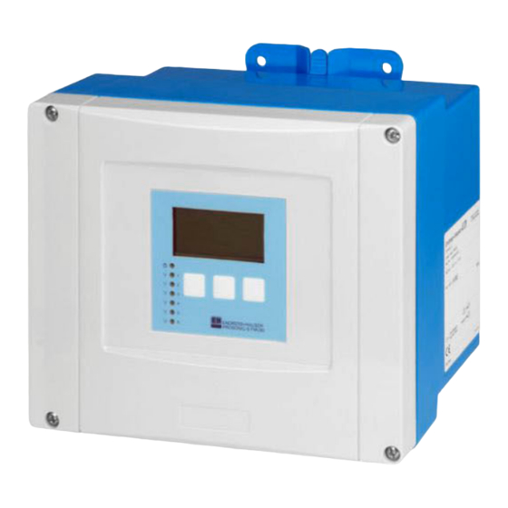
Product description Prosonic S FMU95 PROFIBUS DP Product description Product layout: polycarbonate field housing Valid for: Order code 030 (housing, material) Option 1 (PC field mounting, IP66 NEMA4x) A0035266 1 Parts of the Prosonic S in the polycarbonate field housing... -
Page 9: Product Layout: Din Rail Housing
Prosonic S FMU95 PROFIBUS DP Product description Product layout: DIN rail housing Valid for: Order code 030 (housing, material) Option 2 (DIN rail mounting PBT, IP20) A0035268 3 Parts of the Prosonic S in the DIN rail housing Display and operating module... - Page 10 Product description Prosonic S FMU95 PROFIBUS DP A0035265 4 Parts of the Prosonic S with remote display and operating module DIN rail housing without display and operating module Remote display and operating module for mounting in a cabinet The cable (3m [9.8 ft]) is supplied One possible version of the DIN rail housing is illustrated in the graphic above.
-
Page 11: Incoming Acceptance And Product
• Do the data on the nameplate match the ordering information on the delivery note? • If required (see nameplate): are the Safety Instructions (XA) provided? If one of these conditions is not met, please contact your Endress+Hauser sales office. Product identification The following options are available for the identification of the measuring device: •... -
Page 12: Storage, Transport
Incoming acceptance and product identification Prosonic S FMU95 PROFIBUS DP Storage, transport • Pack the device so that it is protected against impact for storage and transportation. The original packaging provides optimum protection. • Permitted storage temperature: –40 to +60 °C (–40 to 140 °F) -
Page 13: Installation
Prosonic S FMU95 PROFIBUS DP Installation Installation Mounting the polycarbonate field housing Valid for: Order code 030 (housing, material) Option 1 (PC field mounting, IP66 NEMA4x) 5.1.1 Installation conditions Dimensions of polycarbonate field housing ø6.5 (0.26) ≥ ≥ 55 (2.17) 55 (2.17) - Page 14 Installation Prosonic S FMU95 PROFIBUS DP 5.1.2 Mounting the device Wall mounting • The housing bracket supplied can also be used as a drilling template. • Mount the housing bracket on a level surface so that it cannot become warped or bent.
-
Page 15: Mounting The Aluminum Field Housing
Prosonic S FMU95 PROFIBUS DP Installation Mounting the aluminum field housing Valid for: Order code 030 (housing, material) Option 3 (aluminum field mounting, IP66 NEMA4x) 5.2.1 Installation conditions Dimensions of the aluminum field housing 180 (7.09) 7 (0.28) 11 (0.43) ≥55 (2.17) - Page 16 Installation Prosonic S FMU95 PROFIBUS DP 5.2.2 Mounting the device P ro O rd > A0033331 10 Wall-mounted aluminum field housing Endress+Hauser...
-
Page 17: Mounting The Din Rail Housing
Prosonic S FMU95 PROFIBUS DP Installation Mounting the DIN rail housing Valid for: Order code 030 (housing, material) Option 2 (DIN rail mounting PBT, IP20) WARNING The DIN rail housing meets protection class IP06. If the housing is damaged, there is a risk of electric shock at live parts. -
Page 18: Installation Of The Remote Display And Operating Module
Installation Prosonic S FMU95 PROFIBUS DP Installation of the remote display and operating module Valid for: Order code 040 (operation) Option E (illuminated display + keypad, 96x96, panel mounting, IP65 at front) 5.4.1 Mounting methods Mounting in appropriate installation opening A0032560 ... -
Page 19: Mounting The Sensors
Prosonic S FMU95 PROFIBUS DP Installation Installation instructions A0032561 15 Installation of the remote display and operating module Mounting the sensors Further information and the documentation currently available can be found on the Endress+Hauser website: www.endress.com → Downloads. Sensor documentation: •... - Page 20 Installation Prosonic S FMU95 PROFIBUS DP Is the device firmly seated on the DIN rail/is the device correctly mounted on the field housing bracket (visual inspection)? Are the cover screws on the connection compartment cover of the field housing...
-
Page 21: Electrical Connection
Prosonic S FMU95 PROFIBUS DP Electrical connection Electrical connection Connection conditions 6.1.1 Cable specification • Conductor cross-section: 0.2 to 2.5 mm (26 to 14 AWG) • Wire sleeve cross-section: 0.25 to 2.5 mm (24 to 14 AWG) • Min. stripping length: 10 mm (0.39 in) Connecting the device 6.2.1... - Page 22 Electrical connection Prosonic S FMU95 PROFIBUS DP Cable entries Precut openings on the bottom of the housing for the following cable entries: • M20x1.5 (10 openings) • M16x1.5 (5 openings) • M25x1.5 (1 opening) Use a suitable tool to cut out the openings.
- Page 23 Prosonic S FMU95 PROFIBUS DP Electrical connection Access to terminal compartment A0038771 19 Access to terminal compartment: single DIN rail housing unit A0038772 20 Access to terminal compartment: several DIN rail housing units mounted side by side Endress+Hauser...
- Page 24 Electrical connection Prosonic S FMU95 PROFIBUS DP 6.2.4 Terminal assignment Terminal type Prosonic S has plug-in spring terminals. Rigid conductors or flexible conductors with ferrules can be inserted directly into the terminal without using the lever, and create a contact automatically.
-
Page 25: Special Connection Instructions
Prosonic S FMU95 PROFIBUS DP Electrical connection Terminals for synchronization Terminals 39, 40: synchronization of multiple Prosonic S transmitters Terminals for PROFIBUS DP • Terminal 65: PROFIBUS A (RxT/TxD - N) • Terminal 66: PROFIBUS B (RxT/TxD - P) Other elements on the terminal areas •... - Page 26 Electrical connection Prosonic S FMU95 PROFIBUS DP Sync Service Fuse Display HART 0/4…20mA FDU- Sensor Relay 90 … 253 VAC 10 5 … 32 VDC A0035934 22 Connection of the power supply in the polycarbonate field housing Terminal block in field housing for potential equalization Potential equalization;...
- Page 27 Prosonic S FMU95 PROFIBUS DP Electrical connection Sync Service Fuse Display HART 0/4…20mA FDU- Sensor Relay 90 … 253 VAC 10 5 … 32 VDC A0035933 23 Connection of the power supply in the aluminum field housing Potential equalization in aluminum field housing; wired on delivery...
- Page 28 • Signal attenuation: < 9 dB over the entire length of the cable segment • Shielding: copper braided shielding or braided shielding and foil shield Pre-terminated cables are available from Endress+Hauser. T-junction boxes It is recommended to connect the Prosonic S using T-junction boxes. Suitable junction boxes are available from Endress+Hauser. Endress+Hauser...
- Page 29 Prosonic S FMU95 PROFIBUS DP Electrical connection Spurs Information regarding spurs • The cable between the connector and the bus driver in the field device is known as a spur. • Total length of all spurs < 6.6 m (22 ft) at max. 1.5 Mbit/s.
- Page 30 Electrical connection Prosonic S FMU95 PROFIBUS DP Connection diagram for FDU9x → FMU95 FDU90/91/92 max. 30 m FDU90/91/92 max. 300 m YE BK RD FMU95 FDU91F/93/95 FDU91F/93/95 max. 30 m GNYE GNYE max. FDU91F/93/95 300 m YE BK RD FMU95...
- Page 31 Prosonic S FMU95 PROFIBUS DP Electrical connection Potential equalization of metallic sensors in polycarbonate field housing Valid for: Order code 030 (housing, material) Option 1 (PC field mounting, IP66 NEMA4x) Valid for the following sensors • FDU91F • FDU93 • FDU95 These sensors are no longer available but can be connected to the Prosonic S in existing installations.
- Page 32 Electrical connection Prosonic S FMU95 PROFIBUS DP These sensors are no longer available but can be connected to the Prosonic S in existing installations. • FDU96 • FDU83 • FDU84 • FDU85 • FDU86 FDU-Sensor Sync Service Fuse Display PE PE 90 …...
- Page 33 Prosonic S FMU95 PROFIBUS DP Electrical connection FDU-Sensor FDU-Sensor Sync Service Fuse Display GNYE GNYE PE PE 90 … 253 VAC 10.5 … 32 VDC A0038736 28 Potential equalization of metallic sensors in DIN rail housing FDU91F/93/95/96 (FDU83/84/85/86) Metal DIN rail in cabinet...
- Page 34 • Capacitance, wire to shield Max. 60 nF • Protective ground (for FDU91F/93/95) May not be within the shielding. Suitable connection cables are available from Endress+Hauser (→ 74). 6.3.5 Shortening the sensor cable NOTICE Damaged wires or no return conductor may cause malfunctions ‣...
- Page 35 Prosonic S FMU95 PROFIBUS DP Electrical connection FDU91F/93/95 FDU90/91/92 BN (+) BU (-) GNYE GNYE A0035285 29 Shortening the sensor cable FDU90/91/92 sensors FDU91F/93/95 sensors The "BU" (blue) and "BN" (brown) wires are only provided on sensors with a heater.
- Page 36 Electrical connection Prosonic S FMU95 PROFIBUS DP Procedure if synchronizing more than 20 transmitters • Form groups with a maximum of 20 transmitters. • For transmitters within a group, the sensor cables can run in parallel. • The sensor cables of different groups must be separated from one another.
- Page 37 Prosonic S FMU95 PROFIBUS DP Electrical connection Sync Service Fuse Display HART 0/4…20mA FDU- Sensor Relay A0034903 32 Connection of the remote display and operating module Pre-terminated connecting cable 3 m (9.8 ft) with display plug (supplied) Minimum diameter for cable entry 20 mm (0.79 in)
-
Page 38: Operating Options
Operating options Prosonic S FMU95 PROFIBUS DP Operating options Structure and function of the operating menu 7.1.1 Submenus and parameter sets Parameters that belong together are grouped into one parameter set in the operating menu. Each parameter set is identified by a five-digit code. -
Page 39: Access To The Operating Menu Via The Local Display
Prosonic S FMU95 PROFIBUS DP Operating options Access to the operating menu via the local display 7.2.1 Display and operating elements Elements of the display and operating module A0035312 34 Display and operating module Soft key symbols Keys LED to indicate the operational state... - Page 40 Operating options Prosonic S FMU95 PROFIBUS DP Scroll symbols Scroll list available Is displayed if the picklist contains more options than can be shown on the display. All the options in the list can be displayed by pressing repeatedly. Navigation in the envelope curve display (select the "Cyclic" display format) •...
- Page 41 Prosonic S FMU95 PROFIBUS DP Operating options • Displays the next page of measured values (only available if several pages of measured values have been defined; see the "Display" menu). • Opens the "Shortcut" menu, which contains the most important read-only parameters.
- Page 42 Operating options Prosonic S FMU95 PROFIBUS DP 7.2.2 Calling the operating menu from a standard screen (measured value display) • Left button ("Info"): shortcut menu Fast access to the most important parameters: • Tag marking • Envelope curve • Language •...
-
Page 43: System Integration
• www.endress.de → use the search function under "Downloads". • GSD library of the PROFIBUS User Organization (PNO): http://www.PROFIBUS.com • CD-ROM with all the GSD files for Endress+Hauser devices; Order No.: 50097200 Using the GSD files The GSD files must be loaded into a specific subdirectory of the PROFIBUS DP configuration software of the PLC. - Page 44 System integration Prosonic S FMU95 PROFIBUS DP Software addressing • Software addressing takes effect when DIP switch 8 on the PROFIBUS DP terminal area is set to "SW (on)" (factory setting). • The address can then be configured via an operating tool (e.g. "DeviceCare" or "FieldCare").
- Page 45 Prosonic S FMU95 PROFIBUS DP System integration 8.2.2 Bus termination A0038437 39 Bus termination on the device Termination not active Termination active ‣ For the last device on the bus: Switch all four terminating switches to "on" to activate the bus terminating resistor.
-
Page 46: Commissioning
Commissioning Prosonic S FMU95 PROFIBUS DP Commissioning Preparatory steps 9.1.1 Reset to factory settings NOTICE A reset may negatively impact the measurement. ‣ Perform a new basic setup after resetting the device. Using the reset function It is always advisable to reset the device if you want to use a device with an unknown history. - Page 47 Prosonic S FMU95 PROFIBUS DP Commissioning Parameter • Input Assign a sensor to the channel. • Sensor selection Specify the sensor type. Select the Automatic option for FDU9x sensors. Select the Manual option for FDU8x sensors. • Detected Only displayed if Sensor selection = Automatic Displays the sensor type detected automatically.
- Page 48 Commissioning Prosonic S FMU95 PROFIBUS DP 9.3.3 Parameter set "LVL N empty cal." 100% A0034882 41 Empty and full calibration for level measurement FDU9x sensor FMU90/FMU95 transmitter BD Blocking distance Distance between sensor membrane and product surface Empty E...
- Page 49 Prosonic S FMU95 PROFIBUS DP Commissioning Parameter • Unit level Select the level unit. The level is output in this unit if linearization is not performed. • Level N Displays the level F currently measured (from the zero point to the surface of the product) in the selected unit.
- Page 50 Commissioning Prosonic S FMU95 PROFIBUS DP 9.3.6 Parameter set "LVL N Linearisat." 100% 100% 100% 100% 100% A0021476 42 Types of linearization None Table Pyramid bottom Conical bottom Angled bottom Sphere Horizontal cylindrical Intermediate height Navigation Level → Level (LVL) N → Basic setup → LVL N Linearisat.
- Page 51 Prosonic S FMU95 PROFIBUS DP Commissioning • Edit Only displayed if Type = Table. Opens the Edit parameter set to enter the linearization table. • Status table Activates or deactivates the linearization table. • Mode Specifies whether the linearization refers to the level or the ullage.
- Page 52 Commissioning Prosonic S FMU95 PROFIBUS DP 9.3.8 Parameter set "Check value" • This parameter set starts inference echo suppression (mapping). • To record all the interference echoes, perform mapping at the minimum level possible (ideally with an empty vessel). • If it is not possible to empty the vessel during commissioning, record preliminary mapping when the vessel is partially filled.
-
Page 53: Advanced Settings
Prosonic S FMU95 PROFIBUS DP Commissioning 9.3.9 Parameter set "LVL N dist. map." Navigation Level → Level (LVL) N → Basic setup → LVL N dist. map. Parameter • Actual distance Displays the distance D currently measured between the sensor membrane and the surface of the product. - Page 54 Commissioning Prosonic S FMU95 PROFIBUS DP A0036765 45 "Type" = "2x value+bargr." A0036766 46 "Type" = "Value max. size" A0043739 47 "Type" = "Alter. 5x2 val." A0038738 48 "Type" = "Bargr. profil" Configuration of the type of visualization 1.
- Page 55 Prosonic S FMU95 PROFIBUS DP Commissioning Configuration of the display format 1. Navigate to the parameter set: Display → Display format. 2. In the Format parameter, select the number format for length data. 3. In the No. of decimals parameter, specify the number of decimal places that are displayed.
- Page 56 Commissioning Prosonic S FMU95 PROFIBUS DP 9.4.4 Configuration of the cyclic data telegram • The general principles of cyclic data exchange between the measuring device and an automation system (e.g. PLC) are described in Operating Instructions BA00034S, "PROFIBUS DP/PA - Guidelines for planning and commissioning".
- Page 57 Prosonic S FMU95 PROFIBUS DP Commissioning Default configuration of the cyclic data telegram (5-channel version) Valid for FMU95 - *****A... • AI 1 • Bytes 0 - 3: Level 1 (IEEE754); unit: m • Byte 4: Status level 1 • AI 2 •...
-
Page 58: Simulation
Commissioning Prosonic S FMU95 PROFIBUS DP Simulation 9.5.1 Level or volume simulation Navigation Level → Level N → Simulation Parameter • Simulation Select the variable to be simulated (level or volume) • Sim. level value Only displayed if Simulation = Sim. level Enter the level to be simulated. - Page 59 Prosonic S FMU95 PROFIBUS DP Commissioning 9.6.3 Hardware locking Sync Service Fuse Display A0038472 49 Hardware locking Unlocked Locked A write protection switch, which can be used to lock the device against parameter changes, is located on the basic terminal area in the terminal compartment. When the device is locked the symbol is shown on the display.
-
Page 60: Diagnostics And Troubleshooting
Diagnostics and troubleshooting Prosonic S FMU95 PROFIBUS DP Diagnostics and troubleshooting 10.1 General troubleshooting 10.1.1 Calibration error Measured value incorrect Check the Actual distance parameter. • The Actual distance is incorrect: • For measurements in a bypass or ultrasound guide pipe: Set the appropriate option in the LVL N appl. - Page 61 Prosonic S FMU95 PROFIBUS DP Diagnostics and troubleshooting 3. Select which type of curve is to be displayed: envelope curve, floating average curve (FAC), mapping curve. 4. Select the display format: single curve or cyclic. The envelope curve display now appears: A0036421 ...
- Page 62 Diagnostics and troubleshooting Prosonic S FMU95 PROFIBUS DP Envelope curve display in FieldCare/DeviceCare A0036420 1. Click F (functions) on the menu bar. 2. Select the sensor whose envelope curve is to be displayed. 3. To display a single curve, click the Read curve button.
-
Page 63: Overview Of Diagnostic Information
Prosonic S FMU95 PROFIBUS DP Diagnostics and troubleshooting 10.2 Overview of diagnostic information 10.2.1 Error signal Displaying errors that occur during commissioning or operation: • Local display: • Error symbol • Error code • Error description • Cyclic data telegram Status that is transmitted with the measured value. - Page 64 Diagnostics and troubleshooting Prosonic S FMU95 PROFIBUS DP • A 0x 231 Distance: BAD Temperature: GOOD • A 0x 281 Distance: BAD Temperature: BAD • W 0x 281 Distance: UNCERTAIN Temperature: UNCERTAIN • W 0x 501 Distance: BAD Temperature: BAD • A 0x 502 Distance: BAD Temperature: BAD • W 0x 521...
- Page 65 Checksum error → Total reset and recalibration • A 00 111/112/114/115 Electronics defect • → Switch off device and switch it on again. • → If the error persists: call Endress+Hauser Service. • A 00 116 Download error → Repeat download. • A 00 117 Hardware after change not identified •...
- Page 66 Diagnostics and troubleshooting Prosonic S FMU95 PROFIBUS DP • A 00 171 Electronics defect Replace electronics. • A 00 180 Synchronization failure → Check synchronization connection. • A 00 183 Not supported hardware • → Check whether the printed circuit boards installed match the order code for the device.
-
Page 67: Firmware History
Prosonic S FMU95 PROFIBUS DP Diagnostics and troubleshooting 10.3 Firmware history • V01.00.00 (04.2007) Original software BA00344F/00/en/05.06 • V01.01.00 (06.2006) Integration of the FDU90 sensor BA00344F/00/en/07.09 • V01.01.03 (05.2011) New option: binary inputs BA00344F/00/en/13.12 Endress+Hauser... -
Page 68: Maintenance
Maintenance Prosonic S FMU95 PROFIBUS DP Maintenance No special maintenance work is required. 11.1 Exterior cleaning When cleaning the exterior, always use cleaning agents that do not corrode the surface of the housing and the seals. Endress+Hauser... -
Page 69: Repair
Endress+Hauser sales representative. 12.1.2 Repair of Ex-certified devices • Only specialist personnel or Endress+Hauser-Service can carry out repairs to Ex certified devices. • Comply with the prevailing standards, national Ex-area regulations, Safety Instructions (XA) and certificates. -
Page 70: Disposal
Repair Prosonic S FMU95 PROFIBUS DP 2. Return the device if repairs or a factory calibration are required, or if the wrong device was ordered or delivered. 12.4 Disposal Observe the following notes during disposal: • Observe valid federal/national regulations. -
Page 71: Accessories
Accessories Accessories 13.1 Communication-specific accessories 13.1.1 Commubox FXA291 • Connects the CDI interface (Common Data Interface) of Endress+Hauser devices with the USB port of a computer. • Order number: 51516983 • Additional information: Technical Information TI00405C 13.2 Device-specific accessories 13.2.1... - Page 72 Accessories Prosonic S FMU95 PROFIBUS DP 13.2.2 Mounting plate for polycarbonate field housing A0034923 52 Mounting plate for polycarbonate field housing • Compatible with the Prosonic S housing bracket • Pipe diameter: 25 to 50 mm (1 to 2 in) •...
- Page 73 Prosonic S FMU95 PROFIBUS DP Accessories Material 316L (1.4404) Order number 71452327 Frame, 1 400 mm (55.1 in) 3.2 (0.13) 60 (2.36) ø33.7 (1.3) 4 (0.16) 20 (0.8) 55 (2.17) 109 (4.29) (3.94) 130 (5.12) 150 (5.91) A0037800 54 Dimensions.
- Page 74 Accessories Prosonic S FMU95 PROFIBUS DP 13.2.3 Adapter plate for remote display A0035916 55 Use of adapter plate Remote display of Prosonic S FMU9x with adapter plate Installation opening of the remote display of the FMU86x predecessor transmitter To mount the remote display of the Prosonic S FMU9x in the housing of the larger remote display of the FMU86x predecessor •...
- Page 75 Prosonic S FMU95 PROFIBUS DP Accessories FDU95 • Cable type: Li2G2G 2x(0.75)D+1x0.75 • Material: silicone • Ambient temperature:–40 to +150 °C (–40 to +302 °F) • Order number: 71027745 Endress+Hauser...
-
Page 76: Operating Menu
Operating menu Prosonic S FMU95 PROFIBUS DP Operating menu 14.1 Menu "Level → Level (LVL N)" 14.1.1 Submenu "Basic setup" Parameter set L1003 "LVL N sensor sel." • Input • Sensor selection • Detected Parameter set L1004 "LVL N appl. param."... -
Page 77: Menu "Safety Settings
Prosonic S FMU95 PROFIBUS DP Operating menu Parameter set L1017 "LVL N check value" Correction Parameter set L1018 "LVL N correction" Offset Parameter set L1020 "LVL N blocking distance" Blocking distance Parameter set L1019 "LVL N limitation" • Limitation • High limit •... -
Page 78: Overview Of The "Device Properties" Menu
Operating menu Prosonic S FMU95 PROFIBUS DP 14.4 Overview of the "Device properties" menu 14.4.1 Submenu "Operating param." Parameter set D1101 "Distance unit" Distance unit Parameter set D110B "Temperature unit" Temperature unit 14.4.2 Submenu "Tag marking" Parameter set D1102 "Tag marking"... -
Page 79: Menu "Display
Prosonic S FMU95 PROFIBUS DP Operating menu 14.5.3 Submenu "Min/max values" Parameter set IX302 "Level → Level (LVL) N" • Max. value • Min. Value • Reset Parameter set IX302 "Temperature → Temperature sen. N" • Max. value • Min. Value 14.5.4... -
Page 80: Menu "Sensor Management
Operating menu Prosonic S FMU95 PROFIBUS DP 14.7 Menu "Sensor management" 14.7.1 Submenu "Sensor management → FDU sensor N" Parameter set D1106 "US sensor N" • Sensor operation • Sensor priority • Detected • Detection window Endress+Hauser... - Page 84 *71526736* 71526736 www.addresses.endress.com...