Endress+Hauser Proline Prosonic Flow P 500 Manual
Ultrasonic flowmeter
Hide thumbs
Also See for Proline Prosonic Flow P 500:
- Operating instructions manual (224 pages) ,
- Technical information (88 pages) ,
- Functional safety manual (44 pages)
Table of Contents
Advertisement
Quick Links
TI01504D/06/EN/01.21
71508895
2021-05-10
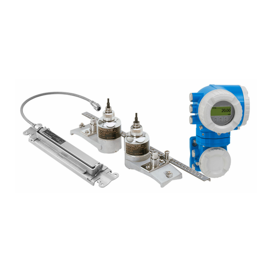
Clamp-on flowmeter for limited spaces in process industries with up to 3 I/Os
Application
• The measuring principle is non-invasive and independent of
pressure, density and conductivity
• Bidirectional measurement of various fluids, e.g. liquid
hydrocarbons and chemicals
Device properties
• Mounting without process interruption
• Wide nominal diameter range: DN 15 to 4000 (½ to 160")
• Medium temperature: –40 to +170 °C (–40 to +338 °F)
• Remote version with up to 3 I/Os
• Backlit display with touch control and WLAN access
• Standard cable between sensor and transmitter
Products
Technical Information
Proline Prosonic Flow P 500
Ultrasonic flowmeter
Solutions
Your benefits
• Constant accuracy even when mounted with short inlet run
thanks to FlowDC (Flow Disturbance Compensation)
• High safety standards – SIL by design, international
hazardous area approvals
• Long-term stable signal – maintenance-free permanent
mounting from outside with coupling pads
• Reliable measurement on various pipe materials – sensor for
GRP and plastic pipes available
• Full access to process and diagnostic information –
numerous, freely combinable I/Os
• Reduced complexity and variety – freely configurable I/O
functionality
• Integrated verification – Heartbeat Technology
Services
Advertisement
Table of Contents

Related Manuals for Endress+Hauser Proline Prosonic Flow P 500


Summary of Contents for Endress+Hauser Proline Prosonic Flow P 500
- Page 1 Solutions Services TI01504D/06/EN/01.21 71508895 2021-05-10 Technical Information Proline Prosonic Flow P 500 Ultrasonic flowmeter Clamp-on flowmeter for limited spaces in process industries with up to 3 I/Os Application Your benefits • The measuring principle is non-invasive and independent of • Constant accuracy even when mounted with short inlet run...
-
Page 2: Table Of Contents
Proline Prosonic Flow P 500 Table of contents About this document ......Vibration- and shock-resistance ....53 Electromagnetic compatibility (EMC) . -
Page 3: About This Document
Proline Prosonic Flow P 500 About this document Symbols Electrical symbols Symbol Meaning Direct current Alternating current Direct current and alternating current Ground connection A grounded terminal which, as far as the operator is concerned, is grounded via a grounding system. -
Page 4: Function And System Design
Proline Prosonic Flow P 500 Symbols in graphics Symbol Meaning 1, 2, 3, ... Item numbers , … Series of steps A, B, C, ... Views A-A, B-B, C-C, ... Sections Hazardous area Safe area (non-hazardous area) Flow direction Function and system design Measuring principle The measuring system uses a measurement method based on the transit time difference. -
Page 5: Measuring System
Proline Prosonic Flow P 500 Measuring system The measuring system consists of a transmitter and two or one sensor sets. The transmitter and sensor sets are mounted in physically separate locations. They are interconnected by sensor cables. The sensors function as sound generators and sound receivers. Depending on the application and version, the sensors can be arranged for measurement via 1, 2, 3 or 4 traverses →... - Page 6 Proline Prosonic Flow P 500 Sensor Prosonic Flow P • Measurement of: • Pure liquids or slightly contaminated liquids DN 15 to 65 (½ to 2½") • Chemicals • Solvents • Liquid hydrocarbons • Acids • Alkalis • Nominal diameter range: DN 15 to 4000 (½ to 160") •...
- Page 7 Proline Prosonic Flow P 500 The sensors can be arranged in different ways: • Mounting arrangement for measurement with 1 sensor set (1 measuring path): • The sensors are located on opposite sides of the pipe (offset at 180°): measurement with 1 or 3 traverses •...
- Page 8 Proline Prosonic Flow P 500 Two-path measurement (2 sensor sets) Horizontal mounting >30° >30° A0043168 A0043309 6 1 traverse 7 2 traverses Operating frequency selection The sensors of the measuring device are available with adapted operating frequencies. These frequencies are optimized for different properties of measuring pipes (material, pipe wall thickness) and media (kinematic viscosity) for the resonance behavior of the measuring pipes.
- Page 9 Proline Prosonic Flow P 500 Kinematic viscosity cSt [mm 0 < v ≤ 10 10 < v ≤ 100 100 < v ≤ 1000 Pipe wall thickness [mm (in)] Transducer frequency (sensor version / number of traverses) 5.9 to 10.0 (0.23 to 0.39)
- Page 10 Proline Prosonic Flow P 500 Measuring mode Two-path measurement with FlowDC (standard configuration) In the case of two-path measurement with FlowDC, the flow is measured by two measurements at the measuring point. For this, the two sensor sets are installed on the measuring pipe, offset at a specific angle to one another (180°...
-
Page 11: Equipment Architecture
Proline Prosonic Flow P 500 Equipment architecture A0027512 9 Possibilities for integrating measuring devices into a system Control system (e.g. PLC) Connecting cable (0/4 to 20 mA HART etc.) Fieldbus Coupler Non-hazardous area Hazardous area: Zone 2; Class I, Division 2 Hazardous area: Zone 1;... - Page 12 Proline Prosonic Flow P 500 Protecting access via hardware write protection Write access to the device parameters via the local display, Web browser or operating tool (e.g. FieldCare, DeviceCare) can be disabled via a write protection switch (DIP switch on the motherboard).
- Page 13 Proline Prosonic Flow P 500 The use of relevant industrial standards and guidelines that have been defined by national and international safety committees, such as IEC/ISA62443 or the IEEE, is recommended. This includes organizational security measures such as the assignment of access authorization as well as technical measures such as network segmentation.
-
Page 14: Input
(temperature, density) to the measuring device: • Analog inputs 4-20 mA • Digital inputs (via HART input or Modbus) Various temperature measuring devices can be ordered from Endress+Hauser: see "Accessories" section → 76 HART protocol The measured values are written from the automation system to the measuring device via the HART protocol. - Page 15 Proline Prosonic Flow P 500 Status input Maximum input values • DC –3 to 30 V • If status input is active (ON): R >3 kΩ Response time Configurable: 5 to 200 ms Input signal level • Low signal: DC –3 to +5 V •...
-
Page 16: Output And Input Variants
Proline Prosonic Flow P 500 Output Output and input variants Depending on the option selected for output/input 1, different options are available for the other outputs and inputs. Only one option can be selected for each output/input 1 to 3. The following tables must be read vertically (↓). - Page 17 Proline Prosonic Flow P 500 Output/input 1 and options for output/input 3 Options for output/input 2 → 16 Order code for "Output; input 1" (020) → Possible options Current output 4 to 20 mA HART Current output 4 to 20 mA HART Ex i passive ↓...
-
Page 18: Output Signal
Proline Prosonic Flow P 500 Output signal Current output 4 to 20 mA HART Order code "Output; input 1" (20): Option BA: current output 4 to 20 mA HART Signal mode Can be set to: • Active • Passive Current range Can be set to: •... - Page 19 Proline Prosonic Flow P 500 Modbus RS485 Physical interface RS485 in accordance with EIA/TIA-485 standard Terminating resistor Integrated, can be activated via DIP switches Current output 4 to 20 mA Order code "Output; input 2" (21)or "Output; input 3" (022):...
- Page 20 Proline Prosonic Flow P 500 Pulse/frequency/switch output Function Can be set to pulse, frequency or switch output Version Open collector Can be set to: • Active • Passive Maximum input values DC 30 V, 250 mA (passive) Open-circuit voltage DC 28.8 V (active) Voltage drop For 22.5 mA: ≤...
- Page 21 Proline Prosonic Flow P 500 Number of switching Unlimited cycles Assignable functions • Off • On • Diagnostic behavior • Limit value • Volume flow • Mass flow • Flow velocity • Electronics temperature • Sound velocity • Totalizer 1-3 •...
-
Page 22: Signal On Alarm
Proline Prosonic Flow P 500 Maximum switching • DC 30 V, 0.1 A capacity (passive) • AC 30 V, 0.5 A Assignable functions • Off • On • Diagnostic behavior • Limit value • Volume flow • Mass flow • Flow velocity •... - Page 23 Proline Prosonic Flow P 500 Pulse/frequency/switch output Pulse output Failure mode Choose from: • Actual value • No pulses Frequency output Failure mode Choose from: • Actual value • 0 Hz • Defined value (f 2 to 12 500 Hz)
-
Page 24: Load
Proline Prosonic Flow P 500 Load Output signal → 18 Ex connection data Safety-related values Order code for Output type Safety-related values "Output; input 1" "Output; input 1" 26 (+) 27 (–) Option BA Current output = 30 V... -
Page 25: Galvanic Isolation
Proline Prosonic Flow P 500 Order code for Output type Intrinsically safe values or NIFW values "Output; input 2"; Output; input 2 Output; input 3 "Output; input 3" 24 (+) 25 (–) 22 (+) 23 (–) Option C Current output 4 to 20 mA... -
Page 26: Power Supply
Proline Prosonic Flow P 500 Supported baud rate • 1 200 BAUD • 2 400 BAUD • 4 800 BAUD • 9 600 BAUD • 19 200 BAUD • 38 400 BAUD • 57 600 BAUD • 115 200 BAUD Data transfer mode •... -
Page 27: Pin Assignment, Device Plug
Proline Prosonic Flow P 500 Order code for "Accessory mounted", option NB "Adapter RJ45 M12 (service interface)" Order code Cable entry/coupling → 28 "Accessory mounted" Cable entry Cable entry Plug M12 × 1 – Pin assignment, device plug Service interface Order code for "Accessories mounted", option NB: Adapter RJ45 M12 (service interface) - Page 28 Proline Prosonic Flow P 500 Down Down A0043219 Securing clamp Connection compartment cover: sensor cable connection Channel 1 upstream / downstream Channel 2 upstream / downstream Connecting the transmitter • Terminal assignment → 26 • Device plug pin assignment → 27...
- Page 29 Proline Prosonic Flow P 500 Connection examples Current output 4 to 20 mA HART 4...20 mA A0029055 10 Connection example for 4 to 20 mA HART current output (active) Automation system with current input (e.g. PLC) Cable shield provided at one end. The cable shield must be grounded at both ends to comply with EMC requirements;...
- Page 30 Proline Prosonic Flow P 500 HART input 4...20 mA A0028763 12 Connection example for HART input with a common negative (passive) Automation system with HART output (e.g. PLC) Active barrier for power supply (e.g. RN221N) Cable shield provided at one end. The cable shield must be grounded at both ends to comply with EMC requirements;...
- Page 31 Proline Prosonic Flow P 500 Current output 4-20 mA 4...20 mA A0028758 14 Connection example for 4-20 mA current output (active) Automation system with current input (e.g. PLC) Analog display unit: observe maximum load → 18 Transmitter 4...20 mA A0028759 ...
- Page 32 Proline Prosonic Flow P 500 Switch output A0028760 17 Connection example for switch output (passive) Automation system with switch input (e.g. PLC) Power supply Transmitter: Observe input values → 20 Pulse output, phase-shifted A0029280 18 Connection example for pulse output, phase-shifted (active) Automation system with pulse input, phase-shifted (e.g.
- Page 33 Proline Prosonic Flow P 500 Relay output A0028760 20 Connection example for relay output (passive) Automation system with relay input (e.g. PLC) Power supply Transmitter: Observe input values → 21 Current input A0028915 21 Connection example for 4 to 20 mA current input...
-
Page 34: Potential Equalization
Proline Prosonic Flow P 500 Potential equalization Requirements For potential equalization: • Pay attention to in-house grounding concepts • Take account of operating conditions like the pipe material and grounding • Connect the medium, sensor and transmitter to the same electrical potential •... - Page 35 Proline Prosonic Flow P 500 Current output 0/4 to 20 mA Standard installation cable is sufficient. Pulse/frequency/switch output Standard installation cable is sufficient. Pulse output, phase-shifted Standard installation cable is sufficient. Relay output Standard installation cable is sufficient. Current input 0/4 to 20 mA Standard installation cable is sufficient.
-
Page 36: Performance Characteristics
Proline Prosonic Flow P 500 Performance characteristics Reference operating • Error limits following ISO/DIS 11631 conditions • Specifications as per measurement report • Accuracy information is based on accredited calibration rigs that are traced to ISO 17025. To obtain measured errors, use the Applicator sizing tool → 75 Maximum measured error o.r. -
Page 37: Repeatability
Proline Prosonic Flow P 500 mounted on a pipe with a nominal diameter of DN 15 (½"), 25 (1"), 40 (1½"), 50 (2") or 100 (4"), respectively. The measurement report guarantees the following error limits at a flow velocity of > 0.3 m/s (1 ft/s) and a Reynolds number >... -
Page 38: Installation
Proline Prosonic Flow P 500 Installation Mounting location A0042039 To prevent measuring errors arising from accumulation of gas bubbles in the measuring tube, avoid the following mounting locations in the pipe: • Highest point of a pipeline. • Directly upstream of a free pipe outlet in a down pipe. -
Page 39: Mounting The Sensor
Proline Prosonic Flow P 500 15 × DN 3 × DN 15 × DN 3 × DN 15 × DN 3 × DN 15 × DN 3 × DN 20 × DN 3 × DN 20 × DN 3 × DN A0042041 ... - Page 40 Proline Prosonic Flow P 500 Screw the nuts onto the U-shaped screws. Position the sensor holder correctly and tighten the nuts uniformly. A0043369 27 Holder with U-shaped screws Sensor holder CAUTION Risk of damaging plastic or glass pipes if the nuts on the U-shaped screws are tightened too much! ‣...
- Page 41 Proline Prosonic Flow P 500 Wrap the strapping bands around the sensor holder and measuring pipe without twisting them. A0043371 28 Positioning the sensor holder and mounting the strapping bands Sensor holder Guide the strapping bands through the strapping band locks.
- Page 42 Proline Prosonic Flow P 500 Sensor holder with strapping bands (medium nominal diameters) Can be used for • Measuring devices with measuring range DN 50 to 4000 (2 to 160") • Mounting on pipes DN ≤ 600 (24") Procedure: Fit the mounting bolt over strapping band 1.
- Page 43 Proline Prosonic Flow P 500 Sensor holder with strapping bands (large nominal diameters) Can be used for • Measuring devices with measuring range DN 50 to 4000 (2 to 160") • Mounting on pipes DN > 600 (24") • 1-traverse mounting or 2-traverse mounting with 180° arrangement •...
- Page 44 Proline Prosonic Flow P 500 A0043374 32 Holder with strapping bands (large nominal diameters) Strap bolt with guide* Strapping band* Tensioning screw *The distance between the strap bolt and strapping band lock must be at least 500 mm (20 in).
- Page 45 Proline Prosonic Flow P 500 13 mm A0043375 33 Holder with welded bolts Welding seam Locking nut Hole diameter max. 8.7 mm (0.34 in) Sensor installation – small nominal diameters DN 15 to 65 (½ to 2½") Requirements • The installation distance is known → 39 •...
- Page 46 Proline Prosonic Flow P 500 Fit the sensor housing on the sensor holder. A0043377 35 Fitting the sensor housing Lock the bracket in place to fix the sensor housing on the sensor holder. A0043378 36 Fixing the sensor housing Connect the sensor cable to the adapter cable.
- Page 47 Proline Prosonic Flow P 500 Sensor installation – medium/large nominal diameters DN 50 to 4000 (2 to 160") Installation for measurement via 1 traverse Requirements • The installation distance and wire length are known → 39 • Strapping bands are pre-assembled...
- Page 48 Proline Prosonic Flow P 500 Fit the sensor holders over the individual mounting bolts and tighten securely with the locking nut. 13 mm A0043381 39 Mounting the sensor holders Attach the coupling pad with the adhesive side facing down on the sensors (→ 77).
- Page 49 Proline Prosonic Flow P 500 Installation for measurement via 2 traverses Requirements • The installation distance is known → 39 • Strapping bands are pre-assembled Material The following material is required for mounting: • Two strapping bands incl. mounting bolts and centering plates where necessary (already pre- assembled →...
- Page 50 Proline Prosonic Flow P 500 Screw the mounting rail onto the sensor holders. A0043385 43 Mounting the sensor holders and mounting rail Attach the coupling pad with the adhesive side facing down on the sensors (→ 77).
-
Page 51: Mounting The Transmitter Housing
Proline Prosonic Flow P 500 Mounting the transmitter Proline 500 transmitter housing Post mounting WARNING Order code for "Transmitter housing", option L "Cast, stainless": cast transmitters are very heavy. They are unstable if they are not mounted on a secure, fixed post. -
Page 52: Special Mounting Instructions
‣ If operating outdoors: Avoid direct sunlight, particularly in warm climatic regions. You can order a weather protection cover from Endress+Hauser. → 73. Storage temperature The storage temperature for all components (except the display modules) corresponds to the ambient temperature range → 52. -
Page 53: Degree Of Protection
Proline Prosonic Flow P 500 Degree of protection Transmitter • As standard: IP66/67, type 4X enclosure • When housing is open: IP20, type 1 enclosure • Display module: IP20, type 1 enclosure Sensor IP68, type 6P enclosure External WLAN antenna... -
Page 54: Mechanical Construction
Proline Prosonic Flow P 500 Mechanical construction Dimensions in SI units Housing of Proline 500 transmitter Non-hazardous area or hazardous area: Zone 2; Class I, Division 2 or Zone 1; Class I, Division 1 A0033788 Order code for "Transmitter housing", option A "Aluminum, coated" and order code for "Integrated ISEM electronics", option B "Transmitter"... - Page 55 Proline Prosonic Flow P 500 Sensor remote version A0041969 49 DN 50 to 4000: measurement with 2 sensor sets [mm] [mm] [mm] [mm] [mm] [mm] [mm] [mm] ⌀ 58 Measuring pipe outer diameter Depends on the conditions at the measuring point (measuring pipe, medium etc.). The dimension can be determined via FieldCare or Applicator.
- Page 56 Proline Prosonic Flow P 500 A0041967 51 DN 50 to 4000: measurement with 1 sensor set [mm] [mm] [mm] [mm] [mm] [mm] [mm] ⌀ 58 Measuring pipe outer diameter Depends on the conditions at the measuring point (measuring pipe, medium etc.). The dimension can be determined via FieldCare or Applicator.
- Page 57 Proline Prosonic Flow P 500 Proline 500 External WLAN antenna mounted on device 105 (4.1) 68 (2.7) 173 (6.8) A0028923 53 Engineering unit mm (in) External WLAN antenna mounted with cable The external WLAN antenna can be mounted separately from the transmitter if the transmission/ reception conditions at the transmitter mounting location are poor.
-
Page 58: Dimensions In Us Units
Proline Prosonic Flow P 500 Dimensions in US units Housing of Proline 500 transmitter Non-hazardous area or hazardous area: Zone 2; Class I, Division 2 or Zone 1; Class I, Division 1 A0033788 Order code for "Transmitter housing", option A "Aluminum, coated" and order code for "Integrated ISEM electronics", option B "Transmitter"... - Page 59 Proline Prosonic Flow P 500 Sensor remote version A0041969 55 DN 2 to 160": measurement with 2 sensor sets [in] [in] [in] [in] [in] [in] [in] [in] 2.20 2.44 ⌀ 2.28 0.20 5.71 4.37 Measuring pipe outer diameter Depends on the conditions at the measuring point (measuring pipe, medium etc.). The dimension can be determined via FieldCare or Applicator.
- Page 60 Proline Prosonic Flow P 500 A0041967 57 DN 2 to 160": measurement with 1 sensor set [in] [in] [in] [in] [in] [in] [in] 2.20 5.71 2.44 ⌀ 2.28 4.37 Measuring pipe outer diameter Depends on the conditions at the measuring point (measuring pipe, medium etc.). The dimension can be determined via FieldCare or Applicator.
-
Page 61: Weight
Proline Prosonic Flow P 500 Proline 500 External WLAN antenna mounted on device 105 (4.1) 68 (2.7) 173 (6.8) A0028923 59 Engineering unit mm (in) External WLAN antenna mounted with cable The external WLAN antenna can be mounted separately from the transmitter if the transmission/ reception conditions at the transmitter mounting location are poor. - Page 62 Proline Prosonic Flow P 500 Window material Order code for "Transmitter housing": • Option A "Aluminum, coated": glass • Option L "Cast, stainless": glass Fastening components for mounting on a post • Screws, threaded bolts, washers, nuts: stainless A2 (chrome-nickel steel) •...
-
Page 63: Human Interface
Proline Prosonic Flow P 500 DN 50 to 4000 (2 to 160"): • Sensor cable, TPE halogen-free • Cable sheath: TPE halogen-free • Cable connector: nickel-plated brass • PTFE sensor cable • Cable sheath: PTFE • Cable plug: stainless steel 1.4301 (304), 1.4404 (316L) Ultrasonic transducer •... -
Page 64: Languages
Proline Prosonic Flow P 500 Languages Can be operated in the following languages: • Via local operation English, German, French, Spanish, Italian, Dutch, Portuguese, Polish, Russian, Turkish, Chinese, Japanese, Korean, Bahasa (Indonesian), Vietnamese, Czech, Swedish • Via Web browser English, German, French, Spanish, Italian, Dutch, Portuguese, Polish, Russian, Turkish, Chinese, Japanese, Korean, Bahasa (Indonesian), Vietnamese, Czech, Swedish •... - Page 65 Proline Prosonic Flow P 500 A0028747 63 Options for remote operation via HART protocol (active) Control system (e.g. PLC) Field Communicator 475 Computer with Web browser (e.g. Internet Explorer) for access to the integrated device Web server or computer with an operating tool (e.g. FieldCare, DeviceCare, AMS Device Manager, SIMATIC PDM) with COM DTM "CDI Communication TCP/IP"...
-
Page 66: Service Interface
Proline Prosonic Flow P 500 A0029437 65 Options for remote operation via Modbus-RS485 protocol (active) Control system (e.g. PLC) Computer with Web browser (e.g. Internet Explorer) for accessing the integrated device Web server or with operating tool (e.g. FieldCare, DeviceCare) with COM DTM "CDI Communication TCP/IP" or Modbus DTM... -
Page 67: Supported Operating Tools
Proline Prosonic Flow P 500 A0041325 Transmitter with integrated WLAN antenna Transmitter with external WLAN antenna LED lit constantly: WLAN reception is enabled on measuring device LED flashing: WLAN connection established between operating unit and measuring device Computer with WLAN interface and Web browser (e.g. Microsoft Internet Explorer, Microsoft Edge) for accessing the integrated device Web server or with operating tool (e.g. - Page 68 Proline Prosonic Flow P 500 Supported operating Operating unit Interface Additional information tools Web browser Notebook, PC or tablet • CDI-RJ45 service Special Documentation for with Web browser interface device • WLAN interface DeviceCare SFE100 Notebook, PC or tablet • CDI-RJ45 service →...
-
Page 69: Historom Data Management
Proline Prosonic Flow P 500 HistoROM data management The measuring device features HistoROM data management. HistoROM data management comprises both the storage and import/export of key device and process data, making operation and servicing far more reliable, secure and efficient. -
Page 70: Certificates And Approvals
The device meets the legal requirements of the applicable EU Directives. These are listed in the corresponding EU Declaration of Conformity along with the standards applied. Endress+Hauser confirms successful testing of the device by affixing to it the CE mark. RCM-tick symbol The measuring system meets the EMC requirements of the "Australian Communications and Media... -
Page 71: Functional Safety
Proline Prosonic Flow P 500 Transmitter Sensor Class I Division 2 Groups A - D Class I, II, III Division 1 Groups A-G Transmitter Sensor Class I Division 2 Groups A - D Class I Division 2 Groups A - D... -
Page 72: Ordering Information
The application packages can be ordered with the device or subsequently from Endress+Hauser. Detailed information on the order code in question is available from your local Endress+Hauser sales center or on the product page of the Endress+Hauser website: www.endress.com. -
Page 73: Heartbeat Technology
• Monitor the process or product quality, e.g. gas pockets. Accessories Various accessories, which can be ordered with the device or subsequently from Endress+Hauser, are available for the device. Detailed information on the order code in question is available from your local Endress+Hauser sales center or on the product page of the Endress+Hauser website: www.endress.com. -
Page 74: Communication-Specific Accessories
Proline Prosonic Flow P 500 Protective cover Is used to protect the measuring device from the effects of the weather: e.g. rainwater, excess heating from direct sunlight. Transmitter Proline 500 Proline 500 transmitter Order number: 71343505 Installation Instructions EA01191D... -
Page 75: Service-Specific Accessories
Accessories Description Applicator Software for selecting and sizing Endress+Hauser measuring devices: • Choice of measuring devices for industrial requirements • Calculation of all the necessary data for identifying the optimum flowmeter: e.g. nominal diameter, pressure loss, flow velocity and accuracy. -
Page 76: System Components
For an overview of the scope of the associated Technical Documentation, refer to the following: • W@M Device Viewer (www.endress.com/deviceviewer): Enter the serial number from nameplate • Endress+Hauser Operations App: Enter the serial number from the nameplate or scan the 2D matrix code (QR code) on the nameplate Standard documentation... -
Page 77: Registered Trademarks
Proline Prosonic Flow P 500 Contents Documentation code cCSAus Ex ia XA02093D cCSAus Ex ec XA02094D cCSAus XP XA02095D Functional Safety Manual Contents Documentation code Proline Prosonic Flow P 500 FY02647D Special documentation Contents Documentation code HART Modbus RS485 Radio approvals for WLAN interface for A309/A310 display module... - Page 80 *71508895* 71508895 www.addresses.endress.com...