Table of Contents
Advertisement
Quick Links
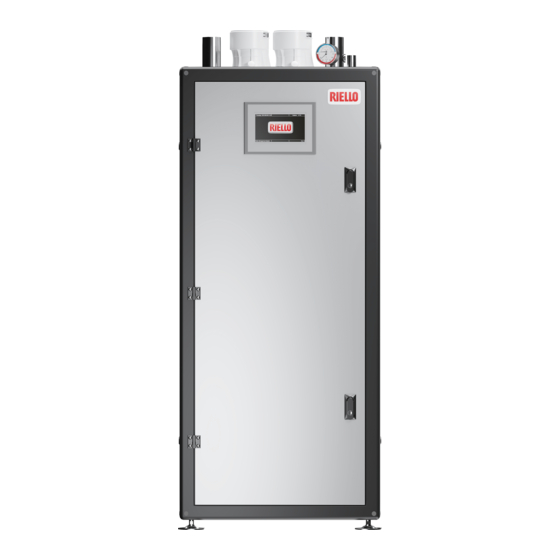
Array AR 399 SE - 500 SE
INSTALLATION, OPERATION AND SERVICE MANUAL
9
WARNING: If the information in this manual is not
followed exactly, a fire or explosion may result causing
property damage, personal injury or loss of life.
Do not store or use gasoline or other flammable
vapors and liquids or other combustible materials in
the vicinity of this or any other appliance. To do so
may result in an explosion or fire.
What to do if you smell gas:
- Do not try to light any appliance;
- Do not touch any electrical switch; do not use any
phone in your building;
- Immediately call your gas supplier from a neighbor's
phone. Follow the gas supplier's instructions;
- If you cannot reach your gas supplier, call the fire
department.
Installation and service must be performed by a
qualified installer, service agency or the gas supplier.
This manual should be maintained in legible
condition and kept adjacent to the boiler or in a safe
place for future reference.
Commercial Boilers
AHRI Standard BTS-2000
Advertisement
Table of Contents
Troubleshooting

Related Manuals for Riello Array AR 399 SE


Summary of Contents for Riello Array AR 399 SE
- Page 1 This manual should be maintained in legible condition and kept adjacent to the boiler or in a safe place for future reference. Commercial Boilers AHRI Standard BTS-2000 Array AR 399 SE - 500 SE INSTALLATION, OPERATION AND SERVICE MANUAL...
- Page 2 MODEL CODE which will provide comfort in the home for many years to come. Array AR 399 SE 20181721 This manual provides information that is essential to the instal- Array AR 500 SE 20181722 lation of the appliance.
-
Page 3: Table Of Contents
1.3.1 General warnings......5 5.3.1 Riello Screen ....... . 38 5.3.2 Module Screen . -
Page 4: General Information
GENERAL INFORMATION GENERAL INFORMATION WARNING: This product is a gas appliance that emits poi- sonous gases; such as CO (Carbon Monoxide). For this reason, it is required that CO detectors be installed in buildings where 1.1 Key to symbols the boiler is installed. Failure to do so may result in severe injury or death. -
Page 5: Warnings
GENERAL INFORMATION 1.3 Warnings The following instructions must be observed − The boiler must only be used for its designated purpose, − Gas fired hot water boiler for either direct vent installation. observing the Installation Instructions. Design according to: ANSI Z21.13-2017 CSA 4.9-2017 – Gas- −... - Page 6 GENERAL INFORMATION Observe these instructions as general warnings: WARNING: If the information in these instructions is not fol- − recommends that an inhibitor - suitable for use with lowed exactly, a fire or explosion may result causing property stainless steel heat exchangers - is used to protect the boil- damage, personal injury or death.
-
Page 7: Product Description
PRODUCT DESCRIPTION 2 PRODUCT DESCRIPTION WARNING: The appliance must not be put in service, even temporarily, when tampered safety devices are not in opera- tion or have been with. 2.1 Description of the appliance A hot water boiler installed above the radiation level or as re- The Array AR SE it is a condensing, pre-mixed thermal module quired by the Authority having jurisdiction, must be provided consisting in a modulating thermal element. -
Page 8: Prolonged Shutdown
PRODUCT DESCRIPTION 2.6 Prolonged Shutdown The sign shall read, in print size no less than one-half (1/2) inch in size, “GAS VENT DIRECTLY BELOW. KEEP CLEAR OF ALL OBSTRUCTIONS”. After prolonged shutdown, the startup procedures and the safety 4. INSPECTION device test procedures of this manual shall be performed to verify The state or local gas inspector of the side wall horizontally vented gas fueled equipment shall not approve the installation unless,... -
Page 9: Identification
(*for installations above 2,000 ft, refer to installation manual) 120 V - 60 Hz less than 3 Amperes Design to ANSI Z21.13-2017 CSA 4.9-2017 Hot Water Boiler Certified by RIELLO S.p.a. Via Nazionale 56/A 65010 Villanova di Cepagatti (PE) Italy CR N W8206.2CL Made in Italy... -
Page 10: System Layout
PRODUCT DESCRIPTION 2.8 System layout Array AR SE Flow-meter 13 Ignition Air pressure switch 14 Combustion chamber Flue gas pressure switch 15 Casing Minimum Water Pressure Switch (set to 7 psi/0.5 bar) 16 Leg Flue gas exhaust connection 17 Thermomanometer 18 Purge valve Gas valve Gas pressure switch 2,5 mbar (only for ARRAY AR 500 SE) -
Page 11: Dimension
PRODUCT DESCRIPTION 2.9 Dimension Array AR SE Dimension Fig. 4... -
Page 12: Technical Specifications
PRODUCT DESCRIPTION 2.10 Technical specifications Unit AR 399 SE AR 500 SE Boiler Category ASME Sect.IV Type of Gas Natural Gas, Propane* BTU/hr 399,220 500,000 Max input rate (kW) (117) (146.5) BTU/hr 39,922 50,000 Min input rate (kW) (11.7) (14.6) Turndown Rate 10:1... -
Page 13: Efficiency Curves
383.00 481.00 AFUE 96,1 96,1 Combustion Efficiency 96,1 96,1 8.5 – 9.5 8.5 – 9.5 2.11 Efficiency Curves ARRAY AR 399 SE - 500 SE 100% 100% input 30% input 20% input Return water temperature (°F) @ 36 Degree Rise... -
Page 14: Pumps
PRODUCT DESCRIPTION 2.12 Pumps 2.14 Positioning of the temperature sensors The Array AR 399 SE and Array AR 500 SE are equipped with a Limit thermostat temperature built-in circulator with integrated check valve. Water temperature sensor Return temperature sensor CAUTION: During the first start-up, and at least once a year, the... - Page 15 PRODUCT DESCRIPTION WATER PRESSURE DROP ARRAY AR 399 SE Q [l/h] 1000 2000 3000 4000 5000 6000 1200 1000 Q [US gpm] Water pressure drop Array AR 399 SE Fig. 7...
- Page 16 PRODUCT DESCRIPTION WATER PRESSURE DROP ARRAY AR 500 SE Q [l/h] 1000 2000 3000 4000 5000 6000 1200 1000 Q [US gpm] Fig. 8 Water pressure drop Array AR 500 SE...
-
Page 17: Service Panel
PRODUCT DESCRIPTION 2.15 Service panel CONTROL PANEL AND SYMBOLS Backlit display (4 13/16" x 1 1/2" / 255mm x 80mm) RESET key: restores normal operations after a safety lock-out MENU key: switches on the main menu ESC key: in menu navigation, it enables you to exit a menu item and go back to the previous one 5 - 9 Navigation keys ◄, ▼, ●, ►, ▲... -
Page 18: Regulations And Guidelines
PRODUCT DESCRIPTION 2.16 Regulations and Guidelines eled equipment is installed in a crawl space or an attic, the hard wired carbon monoxide detector with alarm and bat- tery back-up may be installed on the next adjacent floor level. NOTE: Observe all rules, regulations, standards and guidelines −... -
Page 19: Installation
8 inches w.c. for 399.220 BTU/hr (117 kW) for SE - AR 500 SE. Array AR 399 SE and 500.000 BTU/hr (146.5 kW) for Array AR 500 SE. − The boilers should be mounted on a concrete service/ 3.2 Receiving the Unit... -
Page 20: Setting The Unit
INSTALLATION The minimum surface of ventilation openings is 3.2ft (0.3m ) for gas fuel heating systems. Fig. 12 Clearances (dimensions in inches [mm]) All gas piping, water piping and electrical conduit or cable must Fig. 13 Forklift Handling be arranged so that they do not interfere with the removal of any If a crane is required, the boiler must be lifted through bands. -
Page 21: Installation In Older Systems And Systems Requiring Modifications
INSTALLATION 3.6 Installation in older systems and systems requiring modifications When installing these boilers in older systems or systems requiring modifications, always perform the following checks: − Make sure that the flue is able to withstand the tempera- ture of the combustion gases and that it has been designed and made in compliance with applicable standards. -
Page 22: Asme Pressure Relief Valve
INSTALLATION system by lifting the lever. Make sure the valve discharges Parameters Units Value freely. If the valve fails to operate correctly, replace it with a CaCO Min 50 ; Max 150 new relief valve. Trisodium Phosphate ppm absent − For boilers installed with only a pressure relief valve, the indirect tank (if used) must have a temperature and pres- Chlorine <... -
Page 23: Condensate Drain And Piping
INSTALLATION 3.10 Condensate Drain and Piping 3.11 Water connection The Array AR SE is designed to condense water vapor from the flue NOTE: Before connecting the boiler the protection plugs must products. be removed from the supply, return and condensate drain pipes. -
Page 24: Combustion Gas Exhaust
INSTALLATION Natural Gas and Propane Installation Code, in Canada as well DESCRIPTION Array AR 399 SE Array AR 500 SE as local regulations. Gas inlet 1” NPT 1” NPT Ø Intake pressure with the appliance in the off position has the 3.13 Combustion gas exhaust... -
Page 25: Gas Type Conversion
INSTALLATION WARNING: It is prohibited to use condensate pipes that are not designed for this application, as the condensates acidity flue gas outlet would damage them quickly. 3.14 Gas Type Conversion The heating unit is factory preset for operating with natural gas. This set-up can be changed using the conversion kits supplied by the manufacturer, on demand. -
Page 26: Adjusting And Setting O Limits
INSTALLATION − remove the tube (2), that connects the mixer and the gas valve Model AR 399 SE AR 500 SE Par. 97 Par. 98 − Adjust the O parameter as explained in next chapter − Affix the gas type label from the gas conversion kit to the appliance. -
Page 27: Wiring Diagram
INSTALLATION 3.16 Wiring diagram PWM Out Enable / Disable Exhaust flue temperature sensor Supply temperature sensor Return temperature sensor Water high-limit safety thermostat Low Water Cut Off Flue gas air pressure switch Flow-meter Display and control card Low-voltage terminal TOUCH SCREEN board 0-10V 0-10V input... - Page 28 INSTALLATION Power switch Ignition electrode Spark generator Flame sensor Gas valve Variable speed fan ELECTRODE High-voltage terminal board Indirect tank pump Central heating system pump Boiler circulator J2-6 gr Alarm output J3-5 bl Power supply J3-10 w EXT. Cable colour IGNITER brown J4-6 bl...
-
Page 29: Electronic Control
INSTALLATION 3.17 Electronic control The electronic control interface menu is multi-level. Navigation between the various levels is shown in the figures below. Level 0 displays the Home Screen (Home). Level 1 displays the Main Menu screen. The subsequent levels are activated depending on available sub-menus. -
Page 30: Menu Structure
INSTALLATION 3.17.1 Menu structure... - Page 31 INSTALLATION...
- Page 32 INSTALLATION...
-
Page 33: Commissioning
COMMISSIONING 4 COMMISSIONING 4.4 Warnings Concerning the Gas Supply When starting up the unit for the first time the following must be 4.1 Introduction checked: − That the unit is supplied with the type of fuel that it is con- Before starting the boiler, the user must be correctly instructed by figured to use. - Page 34 COMMISSIONING − Date and Time can be adjusted through the screen below: Ver X.X.XX Ver X.X.XX Fig. 26 Touchscreen Control Panel Stand-by screen Fig. 29 Date & Time screen By touching the logo, the Module screen will appear: − After the Date&Time setting, CH modes can be selected ac- cessing the CH MODE settings screen below: Settings Ver X.X.XX...
- Page 35 COMMISSIONING NOTE: after selecting CH mode 4, enable it either: − CH Mode 1 - Room Themostat & Outdoor Reset: this mode jumpering “Enable/Disable” pins (#11-12) on Terminal strip requires an outdoor sensor, in addition to the room ther- − mostat.
-
Page 36: Minimum Water Flow (Heat Exchanger Protection)
COMMISSIONING 4.5.1 Minimum Water Flow (Heat Exchanger Protection) − DHW mode 2 - Tank with thermostat: hot water is stored in a tank where the temperature is detected by a thermostat (ON/OFF signal). Either a pump or a 3-way valve can be used This unit is self-protected against low water flow. -
Page 37: Multiple Boiler Cascade Installation And Start-Up
COMMISSIONING 4.6 Multiple Boiler Cascade Installation and Start-Up Fig. 41 shows an example of Array boilers installed in a cascade of three units. The built-in control system is capable of managing up to 8 boilers as a single, coordinated heating system. The logical schematic is: Demand: 0-10V / OpenTherm / On-Off System sensor D2 is T outside... -
Page 38: Operation
Ver X.X.XX starting on page 19 must be completed before attempting to start the unit. Fig. 43 Riello Screen 5.2 Control Panel Description The R logo is the entry point of the Control System. By touching it, the system moves to the first operating screen. -
Page 39: Performance Screen
OPERATION 5.3.3 Performance Screen 5.3.4 Service Screen The Control system is able to show the last 10 minutes “real time” The Service screen shows the main parameters of the Service Re- performance of the plant. The screen shows different information minder function. -
Page 40: Cascade Screen
OPERATION Setup, adjustments and checks of combustion parameters can be done using the Low Power, Ignition Power and High Power but- tons. In addition, the High Limit button allows the inspector to carry out the high limit temperature switch functionality test. 5.3.6 Cascade Screen In case of Cascade System, the following screen is displayed. -
Page 41: Error Screen
OPERATION 5.3.9 Error Screen 5.3.11 Module Test Screen For each boiler, the Error screen shows the list of the last 40 errors This screen allows to carry out the same operations shown on occurred on its own modules. paragraph “Test Screen” for each cascade module. The errors are listed in chronological order, under two categories: Blocking errors (auto-reset) and Locking errors (manual reset). - Page 42 OPERATION − Enter the password − Select “(97) IO Configuration” and press the ● button − With the ▲ / ▼ keys change the value following what is in the following table and press the ● key: Par. 97 Model AR 399 SE AR 500 SE (*) Par.
-
Page 43: Troubleshooting
OPERATION 5.5 Troubleshooting FAULT CAUSE SOLUTION − Check the seal of the gaskets and the There is a smell of gas Gas supply circuit leaks pressure test ports/taps for leaks − Check the gasket seals Odour of unburnt gas Flue gas circuit −... - Page 44 OPERATION Modified service functions: (select the modified service functions and enter the values here). Example: Vent Length Parameter changed from 1 to 2 Heating control: Gas type setting (par 98 “Gas Type”) � NG | � LPG CH set point (par. 3) : DHW set point (par.
-
Page 45: Recycling And Disposal
RECYCLING AND DISPOSAL 6 RECYCLING AND DISPOSAL The appliance is manufactured using various materials, such as metal, plastics, and electric and electronic components. At the end of the life cycle, safely remove the components and dispose of them in a responsible manner, in compliance with the installation country's applicable environmental legislation. -
Page 46: Appendix A - Connection Diagram
APPENDIX RECYCLING AND DISPOSAL APPENDIX APPENDIX A - CONNECTION DIAGRAM Int. ionization CONNECTION DIAGRAM 905MN CONTROL BOARD 0...10V J9-1 Ignition 0V(GND) J9-3 BURNER J9-2 Open Thermostat interface Spark Return Room Thermostat ON/OFF J9-4 J10-1 J2 1-6 J10-2 J10-5 J10-6 J1-5 MAINS SUPPLY (120VAC, 60Hz) J1-1... - Page 47 APPENDIX RECYCLING AND DISPOSAL APPENDIX CONNECTION DIAGRAM 905PB DISPLAY CONNECTION DIAGRAM 905PB DISPLAY 905PB05_3R Connector Function PC interface Connection to MN control/Modbus 905PB05_3R Display: RJ-11 Connector: RS485 / Mod BUS J25-1 J25-2 J25-3 1: GND/VSS J25-4 AL-BUS 2: ModBus_B (= Data -) J25-5 3: ModBus_A (= Data +) +24V...
-
Page 48: Appendix B - Maintenance
APPENDIX RECYCLING AND DISPOSAL APPENDIX APPENDIX B - MAINTENANCE Gas Leak Inspection A qualified and adequately trained technician must perform the Inspect all gas piping and gas valve especially pressure inlet to inspection as specified in these instructions before each heating confirm there are no leaks. -
Page 49: Appendix C - Head Available For The System
APPENDIX RECYCLING AND DISPOSAL APPENDIX APPENDIX C - HEAD AVAILABLE FOR THE SYSTEM HEAD AVAILABLE (NO GLYCOL) ∆T = 36°F ∆T = 45°F Array AR 399 SE 3,0 ft 10,0 ft AR 500 SE 8,0 ft 20,0 ft HEAD AVAILABLE (50% MAXIMUM GLYCOL) Array ∆T = 36°F ∆T = 45°F... -
Page 50: Appendix D - De-Rating For Altitude Installation
(input BTU/hr) NOTE: The following chart compensates for the affects of altitude on the energy content of the gas supply. No additional de-rate required. ARRAY AR 399 SE Altitude (ft) -
Page 51: Appendix E - Troubleshooting Table
APPENDIX RECYCLING AND DISPOSAL APPENDIX APPENDIX E - TROUBLESHOOTING TABLE LOCKOUT CODES Error no. Error Description Checks Solutions E2PROM_READ_ERROR Internal software error Control board replacement IGNIT_ERROR Three unsuccessful ignition attempts in a- Check gas supply pressure; a- If the gas supply pressure is a row b- Check ignition spark;... - Page 52 APPENDIX RECYCLING AND DISPOSAL APPENDIX Error no. Error Description Checks Solutions FLUE_SWITCH_NOT_CLOSING The blocked flue sensor is not closed within 10 minutes TSUPPLY_DIFF_ERROR The 2 supply sensors deviate too much for more than 60 seconds TFLUE_DIFF_ERROR The 2 flue sensors deviate too much for more than 60 seconds FILLING_TOO_MUCH Too many automated filling attempts in a...
- Page 53 APPENDIX RECYCLING AND DISPOSAL APPENDIX Error no. Error Description Checks Solutions REFLO2_TOO_LOW Internal software error Control board replacement Flame is detected in a state in which no FALSE_FLAME Control board replacement flame is allowed to be seen LOW_WATER_PRESSURE_ERROR Low water pressure error LOW_WATER_PRESSURE_SENSOR Low water pressure BLOCKED_DRAIN Blocked drain switch is active...
- Page 54 APPENDIX RECYCLING AND DISPOSAL APPENDIX Error no. Error Description Checks Solutions T_SELECTION3_OPEN Selection 3 sensor open T_OPTIONAL1_OPEN Optional 1 sensor open T_OPTIONAL2_OPEN Optional 2 sensor open T_AMBIENT_OPEN Ambient sensor open T_CHIMNEY_CLOSED Chimney sensor shorted T_EXCHANGE1_CLOSED Exchange 1 sensor shorted T_EXCHANGE2_CLOSED Exchange 2 sensor shorted T_SELECTION1_CLOSED Selection 1 sensor shorted...
- Page 55 APPENDIX RECYCLING AND DISPOSAL APPENDIX NOTE − Disconnect both wires. In order to check if the control is functioning properly the following readings can be taken: AL Link 24VDC (with S1 Switch On and open circuit). Voltage is variable while in normal operation depending on data stream.
- Page 56 APPENDIX RECYCLING AND DISPOSAL APPENDIX − Disconnect the multimeter and reconnect the wires, as shown in the picture below. − 1 (NC) 3 (COM) 2 (NO) Fig. 61 Wired pressure switch − Test the pressure switch on the other side of the boiler (module 4 or 8);...
-
Page 57: Appendix F - Typical Water System Schematics
APPENDIX RECYCLING AND DISPOSAL APPENDIX APPENDIX F - TYPICAL WATER SYSTEM SCHEMATICS Layout 1: circuit with boiler directly linked to heating system (check that the pump's discharge head is sufficient to ensure ade- quate circulation) Layout 2: circuit with boiler directly linked to heating system and indirect DHW tank. (check that the pump's discharge head is sufficient to ensure adequate circulation) Outdoor temperature Isolating valve... - Page 58 APPENDIX RECYCLING AND DISPOSAL APPENDIX Layout 3: circuit with boiler connected to a heating system via a separator Layout 4: circuit with boiler linked to Indirect DHW tank and heating system via a separator Isolating valve Water softener filter Outdoor temperature sensor Check valve Pressure reducer...
- Page 59 APPENDIX RECYCLING AND DISPOSAL APPENDIX Layout 5: circuit with boiler linked to heating system and indirect DHW. tank via a separator Isolating valve Water softener filter Outdoor temperature Check valve Pressure reducer sensor Anti-scald mixing valve Domestic water storage tank High temperature Expansion tank 10 Diverter valve...
- Page 60 APPENDIX RECYCLING AND DISPOSAL APPENDIX Layout 6: circuit with boiler linked to 2 Indirect DHW tank and heating system via a separator Isolating valve Water softener filter Outdoor temperature Check valve Pressure reducer sensor Anti-scald mixing valve Domestic water storage tank High temperature Expansion tank 10 Pump...
-
Page 61: Appendix G - Venting Size Data
MAX equiv. ft MAX equiv. mt MAX equiv. ft ARRAY AR 399 SE ARRAY AR 500 SE Fittings as well as pipe lengths must be calculated as part of the equivalent length, according to the following table: 45° ELBOW - 4”... -
Page 62: Appendix H - Exhaust Terminals And Air Inlet Clearances
APPENDIX RECYCLING AND DISPOSAL APPENDIX APPENDIX H - EXHAUST TERMINALS AND AIR INLET CLEARANCES Direct vent (sealed combustion) Fan assisted appliance (Room air for combustion) Forced air inlet Forced air inlet Gravity air inlet Gravity air inlet Exhaust terminal Exhaust terminal X1 1 foot (305 mm) X1 1 foot (305 mm) X2 See Note 1) - Page 63 APPENDIX RECYCLING AND DISPOSAL APPENDIX APPROVED EXAMPLES OF HORIZONTAL AND VERTICAL Horizontal venting system (room air only); X≥4” (102 mm) VENTING INSTALLATION NOTE: Place pipe supports a minimum of every 5 feet (1.525 mm) for horizontal and vertical runs, beginning with a sup- port near the boiler unless the vent manufacturer or local code states smaller intervals.
- Page 64 APPENDIX RECYCLING AND DISPOSAL APPENDIX Horizontal venting system (sealed combustion); X≥4” (102 Vertical venting system (sealed combustion); X > 12" (305 mm); Y ≥12” (305 mm) mm); Y 12" (305 mm) above maximum snow level or at least 24" (610 mm) whichever is greater Vertical venting system (sealed combustion);...
- Page 65 APPENDIX RECYCLING AND DISPOSAL APPENDIX Horizontal venting system (sealed combustion); X≥4” (102 Vertical venting system (sealed combustion); X > 12” (305 mm); Y 12" (305 mm) above maximum snow level or at least 24" (610 mm) whichever is great Horizontal concentric system (sealed combustion)
- Page 66 APPENDIX RECYCLING AND DISPOSAL APPENDIX MULTIPLE BOILERS Vertical venting system (sealed combustion) When installing multiple air and vent terminations, be sure that: − The clearance between the vent and air termination are in accordance with the figures shown in this chapter −...
- Page 67 APPENDIX RECYCLING AND DISPOSAL APPENDIX Multiple air and vent vertical terminations; X ≥ 12" (305 mm); Multiple air and vent vertical termination ; X≥ 12" (305 mm); Y≥ 12" (305 mm) Y≤ 25" (635 mm); Z = 12" (305 mm) to 16" (406 mm) Air intake Vent Vent terminals...
- Page 68 APPENDIX RECYCLING AND DISPOSAL APPENDIX VENTING MATERIAL the local, state and federal building codes. − All vent pipes must be installed according to the vent man- Array boilers must be vented and supplied with combustion and ufacturer’s instructions. ventilation air as described in this section. −...
- Page 69 APPENDIX RECYCLING AND DISPOSAL APPENDIX COMBUSTION AIR COMBUSTION AIR FROM INSIDE THE BUILDING When combustion air is provided from within the building, it must Air supply is a direct requirement of ANSI 223.1, NFPA-54, CSA B149.1 be supplied through two permanent openings in an interior wall. and local codes.
-
Page 70: Appendix I - Sensor Resistance
APPENDIX RECYCLING AND DISPOSAL APPENDIX APPENDIX I - SENSOR RESISTANCE SENSOR RESISTANCE TABLE Temperature °F (°C) Resistance [Ω] Testing tolerance ±10% 32 (0) 27396 41 (5) 22140 50 (10) 17999 59 (15) 14716 68 (20) 12099 77 (25) 10000 86 (30) 8308 95 (35) 6936... -
Page 71: Appendix J - List Of Parameters
APPENDIX RECYCLING AND DISPOSAL APPENDIX APPENDIX J - LIST OF PARAMETERS (WITH RANGES AND DEFAULT VALUES) Parameters are listed base on the reference menu. Reference Menu Access type Boiler parameters menu End user System cascade settings menu Installer Boiler cascade settings menu Appliance configuration menu Nr. - Page 72 APPENDIX RECYCLING AND DISPOSAL APPENDIX Nr. dis- Par. Default Access Menu played Description Range Category setting type Display Design Limits the minimum value that can be assigned to Supply 39 - 180 the set-point in heating mode (does not apply to 86 (30) °F (°C) Heating...
- Page 73 APPENDIX RECYCLING AND DISPOSAL APPENDIX Nr. dis- Par. Default Access Menu played Description Range Category setting type Display tank Establishes the DHW indirect storage tank set-point 104-160 122 (50) °F (°C) set- Par. 35 in mode 2. (40-71) point Speed Defines the fan rpm at max.
- Page 74 APPENDIX RECYCLING AND DISPOSAL APPENDIX Nr. dis- Par. Default Access Menu played Description Range Category setting type Display Prog. 0 Disabled Defined Input The value of this parameter is defined by Par. 97. General 1 Enabled by Par. 97 0 Disabled 1 General Pump 2 CH Pump 3 DHW Pump...
- Page 75 APPENDIX RECYCLING AND DISPOSAL APPENDIX Nr. dis- Par. Default Access Menu played Description Range Category setting type Display Activates bleeding the system's air. To activate air bleeding, it is necessary to switch on the boiler and change the parameter from "No" to "Yes". Wait for one minute.
- Page 76 APPENDIX RECYCLING AND DISPOSAL APPENDIX Nr. dis- Par. Default Access Menu played Description Range Category setting type Display Defines how many degrees the temperature mea- Hyst. Up sured by the primary circuit's sensor must go above 0 - 72 Quick the set-point in order for the subsequent boiler to 11 (6) °F (°C)
- Page 77 APPENDIX RECYCLING AND DISPOSAL APPENDIX Nr. dis- Par. Default Access Menu played Description Range Category setting type Display Managing, Boiler Stand- Defines the way in which the boiler is managed. Stand-alone, Cascade Address alone Dependent Max. Defines the maximum decrease in the primary Setp.
-
Page 78: Appendix K - Flowcharts
APPENDIX RECYCLING AND DISPOSAL APPENDIX APPENDIX K - FLOWCHARTS SINGLE MODULE Module in Stop pump Stand-by Demand for Post pump module ready Start pump Supply Temp Start fan lower than Setpoint Module Blocking CH flow Start burner (*) error is above min_flow? BURN Burn: Based on delta of Supply sensor... - Page 79 APPENDIX RECYCLING AND DISPOSAL APPENDIX BURNER IGNITION SEQUENCE Start burner Pre-Purge 0 Pre-Purge 1 Fan on ignition speed Fan on ignition Blocking error speed within time? Pre ignition on Ignite: ignition on, Gas Valve open Flame Proving, Checking flame Flame Current Ignition Tries Above Minimal less than 3?
- Page 80 APPENDIX RECYCLING AND DISPOSAL APPENDIX MODULE CASCADE (STAND-ALONE BOILER) Boiler in Stop boiler Locking error stand-by pump Boiler error Locking Present? error? Blocking error Post pump Boiler Heat ready Demand? Calculate Start boiler boiler pump setpoint Boiler Temperature Clear demand Remove all higher than active modules setpoint...
- Page 81 APPENDIX RECYCLING AND DISPOSAL APPENDIX MODULE CASCADE (STAND-ALONE BOILER): ADD/REMOVE MODULE Add module function Delay period for starting new module is 0? Open Air damper Air damper open? Are we allowed to add another dependent? Add dependent to the cascade demand Reload delay time Update demand flags...
- Page 82 APPENDIX RECYCLING AND DISPOSAL APPENDIX ERROR CHECKING CYCLE Stand-by Boiler Min/Max Gas pressure Locking error switches are closed? Boiler Blocked Blocking Flue pressure error switch is closed Boiler Water Blocking pressure switch is error closed? Module High limit Locking error sensor is closed? Supply/return/ Blocking...
- Page 83 RECYCLING AND DISPOSAL...
- Page 84 RIELLO S.p.A. Via Ing. Pilade Riello, 7 37045 - Legnago (VR) www.rielloboilers.com Riello North America 2165 Meadowpine Blvd. Mississauga, ON L5N6H6 CANADA Technical Support Hotline: 1.800.474.3556 Professional Resources: www.riello.com The manufacturer strives to continuously improve all products: appearance, dimensions, technical specifications, standard equipment and...