Endress+Hauser RMM621 Brief Operating Instructions
Application manager, decentralized process monitoring
Hide thumbs
Also See for RMM621:
- Operating manual (12 pages) ,
- Operating instructions manual (76 pages)

Related Manuals for Endress+Hauser RMM621


Summary of Contents for Endress+Hauser RMM621
- Page 1 Brief Operating Instructions RMM621 Application Manager Decentralized Process Monitoring S. 3 < P. 17 P. 31 P. 45 > P. 59 P. 73 KA228R/09/a6/07.07 71020750...
-
Page 3: Table Of Contents
Inhaltsverzeichnis Inhaltsverzeichnis 1 Sicherheitshinweise..........4 1.1 Bestimmungsgemäße Verwendung . -
Page 4: Sicherheitshinweise
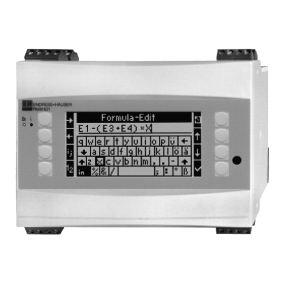
Betriebsanleitung und den zusätzlichen Anleitungen auf der mitgelieferten CD-ROM. Bestimmungsgemäße Verwendung Der RMM621 Application Manager ist ein Gerät zur Verrechnung von physikalischen Größen, die von angeschlossenen Sensoren zur Verfügung gestellt werden. Zur Verrechnung können hinterlegte Formeln, aber auch frei definierbare und eingebbare Formeln verwendet werden. -
Page 5: Rücksendung
Sicherheitshinweise Rücksendung Für eine Rücksendung, z. B. im Reparaturfall, ist das Gerät geschützt zu verpacken. Optimalen Schutz bietet die Originalverpackung. Reparaturen dürfen nur durch die Serviceorganisation Ihres Lieferanten durchgeführt werden. Hinweis! Bitte legen Sie für die Einsendung zur Reparatur eine Notiz mit der Beschreibung des Fehlers und der Anwendung bei. -
Page 6: Identifizierung
2.1.1 Typenschild Das richtige Gerät? Vergleichen Sie bitte den Bestellcode auf dem Typenschild am Gerät mit dem auf dem Liefer- schein. G09-RMM621ZZ-18-10-xx-xx-000 Abb. 1: Typenschild RMM621 Bestellcode Seriennummer Lieferumfang Der Lieferumfang des Gerätes besteht aus: • Application Manager für Hutschienenmontage •... -
Page 7: Zertifikate Und Zulassungen
Identifizierung Zertifikate und Zulassungen CE-Zeichen, Konformitätserklärung Das Gerät ist nach dem Stand der Technik betriebssicher gebaut und geprüft und hat das Werk in sicherheitstechnisch einwandfreiem Zustand verlassen. Das Gerät berücksichtigt die einschlägigen Normen und Vorschriften nach IEC 61010 "Sicher- heitsbestimmungen für elektrische Mess-, Steuer, Regel- und Laborgeräte". Das in dieser Betriebsanleitung beschriebene Gerät erfüllt somit die gesetzlichen Anforderungen der EU-Richtlinien. -
Page 8: Montage
0,5 m/s erforderlich. 3.1.1 Betriebstemperatur -20 bis 50 °C (-4 bis 122 °F) 3.1.2 Einbaumaße G09-RMM621XX-06-10-xx-xx-000 Abb. 2: Abmessungen des RMM621 3.1.3 Einbauort Hutschienenmontage nach IEC 60715 im Schaltschrank. Der Einbauort muss frei von Vibration sein. 3.1.4 Einbaulage Keine Einschränkungen. - Page 9 Montage Abb. 3: Gerätemontage auf Hutschiene 3.2.1 Einbau von Erweiterungskarten " Achtung! Bei Verwendung von Erweiterungskarten ist die Belüftung mit einem Luftstrom von mindestens 0,5 m/s erforderlich. Sie können das Gerät mit unterschiedlichen Erweiterungskarten bestücken. Es stehen hierzu maximal drei Steckplätze im Gerät zur Verfügung. Die Steckplätze für die Erweiterungskarten sind am Gerät mit B, C und D (→...
-
Page 10: Einbaukontrolle
Montage Die neue Erweiterungskarte wird vom Gerät automatisch erkannt, nachdem das Gerät korrekt verdrahtet und wieder in Betrieb genommen worden ist (siehe Kapitel ’Inbetrieb- nahme’). Hinweis! Wenn Sie eine Erweiterungskarte ausbauen und nicht durch eine andere ersetzen, müssen Sie den leeren Steckplatz mit einer Blindabdeckung verschließen. Abb. -
Page 11: Verdrahtung
Verdrahtung Verdrahtung Verdrahtung auf einen Blick Abb. 5: Slot-Belegung (Grundgerät) Klemmenbelegung Klemme Klemmenbelegung Slot Eingang (Pos.-Nr.) + 0/4...20 mA/PFM/Impuls-Eingang 1 A oben vorn (A I) Strom/PFM/Impuls-Eingang 1 Signalmasse für 0/4...20 mA/PFM/Impuls-Eingang Masse Sensorversorgung 1 24 V Sensorversorgung 1 + 0/4...20 mA/PFM/Impuls-Eingang 2 A oben hinten (A II) Strom/PFM/Impuls-Eingang 2 Signalmasse für 0/4...20... - Page 12 Verdrahtung Klemme Klemmenbelegung Slot Eingang (Pos.-Nr.) + 0/4...20 mA/PFM/Impuls-Eingang 1 E oben vorn (E I) Strom/PFM/Impuls-Eingang 1 Signalmasse für 0/4...20 mA/PFM/Impuls-Eingang Masse Sensorversorgung 1 24 V Sensorversorgung 1 + 0/4...20 mA/PFM/Impuls-Eingang 2 E oben hinten (E II) Strom/PFM/Impuls-Eingang 2 Signalmasse für 0/4...20 mA/PFM/Impuls-Eingang Masse Sensorversorgung 2 24 V Sensorversorgung 2...
- Page 13 Verdrahtung Klemmenbelegung Erweiterungskarte Digital Klemme Klemmenbelegung Slot Ein- und Ausgang (Pos.-Nr.) B, C, D oben vorn Digitaleingänge E1...3 (B I, C I, D I) Signalmasse E1...3 B, C, D oben hinten Digitaleingänge E4...6 (B II, C II, D II) Signalmasse E4...6 Relais 1 Common (COM) B, C, D unten vorn Relais 1...
- Page 14 Verdrahtung Klemmenbelegung Erweiterungskarte U-I-TC Klemme Klemmenbelegung Slot Ein- und Ausgang (Pos.-Nr.) -10...+10 V Eingang 1 B, C, D oben vorn U-I-TC Eingang 1 (B I, C I, D I) -1...+1 V, TC Eingang 1 0...20 mA Eingang 1 Signalmasse Eingang 1 -10...+10 V Eingang 2 B, C, D oben hinten U-I-TC Eingang 2...
-
Page 15: Anschlusskontrolle
Bedienung und Inbetriebnahme Anschlusskontrolle Führen Sie nach der elektrischen Installation des Gerätes folgende Kontrollen durch: Gerätezustand und -spezifikationen Hinweise Sind Gerät oder Kabel beschädigt (Sichtkontrolle)? Elektrischer Anschluss Hinweise Stimmt die Versorgungsspannung mit den Angaben auf dem Typenschild überein? 90 bis 250 V AC (50/60 Hz) 20 bis 36 V DC 20 bis 28 V AC (50/60 Hz) Sind alle Klemmen in ihrem richtigen Steckplatz fest eingerastet? Stimmt die Codie-... - Page 17 Table of contents Table of contents Safety instructions ........18 Designated use .
-
Page 18: Safety Instructions
Operating Instructions and the additional instructions on the supplied CD-ROM. Designated use The RMM621 Application Manager is a device for calculating physical variables made available by connected sensors. Stored formulae and also formulae which can be defined and entered freely can be used for calculation. These formulae which can be entered freely can be edited ®... -
Page 19: Return
Safety instructions Return For a return, e.g. in case of repair, the device must be sent in protective packaging. The original packaging offers the best protection. Repairs must only be carried out by your supplier's service organization. Note! When sending for repair, please enclose a note with a description of the error and the applica- tion. -
Page 20: Identification
2.1.1 Nameplate The correct device? Please compare the order code on the nameplate of the device to the code on the delivery note. G09-RMM621ZZ-18-10-xx-xx-000 Fig. 1: RMM621 nameplate Order code Serial number Scope of delivery The scope of delivery of the device comprises: •... -
Page 21: Certificates And Approvals
Identification Certificates and approvals CE mark, declaration of conformity The device has been constructed and tested to state-of-the-art operational safety standards and left the factory in perfect condition as regards technical safety. The device meets the relevant standards and directives as per IEC 61010 "Safety requirements for electrical equipment for measurement, control and laboratory use". -
Page 22: Installation
3.1.1 Operating temperature -20 to 50 °C (-4 to 122 °F) 3.1.2 Dimensions G09-RMM621XX-06-10-xx-xx-000 Fig. 2: Dimensions of the RMM621 3.1.3 Mounting location Top-hat rail mounting as per IEC 60715 in the cabinet. The mounting location must be free from vibrations. - Page 23 Installation Fig. 3: Mounting device on top-hat rail 3.2.1 Installing extension cards " Caution! When using extension cards, venting with an air current of at least 0.5 m/s is necessary. You can equip the device with various extension cards. A maximum of three slots are available in the device for this.
-
Page 24: Post-Installation Check
Installation Note! If you remove an extension card and do not replace it with another card, you must seal the empty slot with a blanking cover. Fig. 4: Installing an extension card (example) Item 1: catch on the rear of the device Item 2: catches on the bottom of the device Items A - E: identifier for slot assignment Post-installation check... -
Page 25: Wiring
Wiring Wiring Quick wiring guide Fig. 5: Slot assignment (basic unit) Terminal assignment Terminal Terminal assignment Slot Input (item no.) + 0/4 to 20 mA/PFM/pulse input 1 A top, front (A Current/PFM/pulse input 1 Ground for 0/4 to 20 mA/PFM/pulse input Sensor power supply ground 1 24 V sensor power supply 1 + 0/4 to 20 mA/PFM/pulse input 2... - Page 26 Wiring Terminal Terminal assignment Slot Input (item no.) + 0/4 to 20 mA/PFM/pulse input 1 E top, front (E Current/PFM/pulse input 1 Ground for 0/4 to 20 mA/PFM/pulse input Sensor power supply ground 1 24 V sensor power supply 1 + 0/4 to 20 mA/PFM/pulse input 2 E top, rear (E Current/PFM/pulse input 2...
- Page 27 Wiring Terminal assignment of extension card, digital Terminal Terminal assignment Slot Input and output (item no.) B, C, D top, Digital inputs E1 to 3 front (B I, C I, D I) Signal ground E1 to 3 B, C, D top, Digital inputs E4 to 6 rear (B II, C II, D...
- Page 28 Wiring Terminal assignment for expansion card, U-I-TC Terminal Terminal assignment Slot Input and output (item no.) -10 to +10 V Input 1 B, C, D top, U-I-TC Input 1 front (B I, C I, -1 to +1 V, TC Input 1 D I) 0 to 20 mA Input 1 Signal ground Input 1...
-
Page 29: Post-Connection Check
Operation and commissioning Post-connection check After completing the device's electrical installation, carry out the following checks: Device status and specifications Notes Is the device or cable damaged (visual inspection)? Electrical connection Notes Does the supply voltage match the information on the nameplate? 90 to 250 V AC (50/60 Hz) 18 to 36 V DC 20 to 28 V AC (50/60 Hz) - Page 31 Sommaire Sommaire Conseils de sécurité ........32 Utilisation conforme .
-
Page 32: Conseils De Sécurité
CD-ROM. Utilisation conforme Le RMM621 "Application Manager" est un appareil destiné au calcul de grandeurs physiques mises à disposition par les capteurs raccordés. Pour le calcul on peut utiliser les formules mémo- risées, mais également des formules librement définissables ou à... -
Page 33: Retour De Matériel
Conseils de sécurité Retour de matériel Dans le cas d'un retour, par ex. pour réparation, il convient de bien emballer l'appareil. Une protection optimale est assurée par l'emballage d'origine. Les réparations ne doivent être effectuées que par le service après-vente de votre fournisseur. Remarque ! Lors d'un retour pour réparation, joindre une note avec une description du défaut et de l'appli- cation. -
Page 34: Identification
S'agit-il du bon appareil ? Comparez la structure de commande sur la plaque signalétique de l'appareil avec celle sur le bulletin de livraison. G09-RMM621ZZ-18-10-xx-xx-000 Fig. 1: Plaque signalétique RMM621 Structure de commande Numéro de série Livraison L'ensemble livré comprend : •... -
Page 35: Certificats Et Agréments
Identification Certificats et agréments Marquage CE, déclaration de conformité L'appareil est construit de manière sûre d'après les derniers progrès techniques et a quitté nos établissements dans un état parfait. L'appareil tient compte des normes et directives en vigueur selon CEI 61010 "Directives de sécurité... -
Page 36: Montage
3.1.1 Température de service -20 à 50 °C (-4 à 122 °F) 3.1.2 Dimensions G09-RMM621XX-06-10-xx-xx-000 Fig. 2: Dimensions du RMM621 3.1.3 Point d'implantation Montage sur rail profilé selon CEI 60715 en armoire électrique. Le point d'implantation doit être exempt de vibrations. - Page 37 Montage Fig. 3: Montage d'appareil sur rail profilé 3.2.1 Montage de cartes d'extension " Attention ! Si vous utilisez des cartes d'extension, il faut une ventilation avec un flux d'air d'au moins 0,5 m/s. Vous pouvez équiper l'appareil avec différentes cartes d'extension. L'appareil dispose à cet effet de trois emplacements.
-
Page 38: Contrôle De L'implantation
Montage La nouvelle carte d'extension est automatiquement reconnue par l'appareil après que ce dernier a été correctement câblé et à nouveau mis en service (voir chapitre "Mise en service"). Remarque ! Si vous démontez une carte d'extension et si vous ne la remplacez pas par une autre, il convient d'occulter l'emplacement vide avec un cache. -
Page 39: Câblage
Câblage Câblage Câblage en bref Fig. 5: Occupation des slots (appareil de base) Occupation des bornes Borne Occupation des bornes Slot Entrée (N° pos.) + 0/4...20 mA/PFM/entrée impulsion 1 A en haut devant (A Courant/PFM/entrée impulsion 1 Masse du signal pour 0/4...20 mA/PFM/entrée impulsions Masse alimentation de capteur 1 24 V alimentation de capteur 1... - Page 40 Câblage Borne Occupation des bornes Slot Entrée (N° pos.) + 0/4...20 mA/PFM/entrée impulsion 1 E en haut devant (E Courant/PFM/entrée impulsion 1 Masse du signal pour 0/4...20 mA/PFM/entrée impulsions Masse alimentation de capteur 1 24 V alimentation de capteur 1 + 0/4...20 mA/PFM/entrée impulsions 2 E en haut derrière (E Courant/PFM/entrée impulsions 2...
- Page 41 Câblage Occupation des bornes carte d'extension digitale Borne Occupation des bornes Slot Entrée et sortie (N° pos.) B, C, D en haut Entrées digitales E1...3 devant (B I, C I, D I) Masse signal E1...3 B, C, D en haut der- Entrées digitales E4...6 rière (B II, C II, D II)
- Page 42 Câblage Occupation des bornes carte d'extension U-I-TC Borne Occupation des bornes Slot Entrée et sortie (N° pos.) -10...+10 V Entrée 1 B, C, D en haut Entrèe U-I-TC 1 devant -1...+1 V, Entrèe TC 1 (B I, C I, D I) 0...20 mA Entrée 1 Masse signal Entrée 1 -10...+10 V Entrée 2...
-
Page 43: Contrôle Du Raccordement
Utilisation et mise en service Contrôle du raccordement Après l'installation électrique de l'appareil, procéder aux contrôles suivants : Etat et spécifications de l'appareil Remarques L'appareil ou le câble sont-ils endommagés (contrôle visuel) ? Raccordement électrique Remarques La tension d'alimentation correspond-elle aux indications sur la plaque signaléti- 90 à... - Page 45 Indice Indice Note sulla sicurezza ........46 Uso corretto .
-
Page 46: Note Sulla Sicurezza
CD-ROM incluso nella fornitura. Uso corretto Il dispositivo RMM621 Application Manager è un sistema per la contabilizzazione delle variabili fisiche, fornite dai sensori connessi. Per la contabilizzazione possono essere impiegate delle formule predefinite e, anche, liberamente impostabili. Queste ultime possono essere immesse ®... -
Page 47: Resi
Note sulla sicurezza Resi In caso di reso, ad es. in conto riparazione, il dispositivo deve essere perfettamente imballato. L'imballaggio originale garantisce una sicurezza ottimale. Le riparazioni possono essere eseguite solo dal servizio di assistenza del fornitore. Nota! Si prega di allegare alla riparazione una nota con la descrizione del guasto e dell'applicazione. Caratteri e simboli di sicurezza Le indicazioni per la sicurezza, riportate in questo Manuale, sono evidenziate con i seguenti caratteri e simboli:... -
Page 48: Identificazione
Il dispositivo è quello richiesto? Confrontare il codice d'ordine inciso sulla targhetta del dispositivo con quello riportato sui documenti di consegna. G09-RMM621ZZ-18-10-xx-xx-000 Fig. 1: Targhetta del RMM621 Codice d'ordine Numero di serie Contenuto della fornitura La fornitura del sistema di gestione e controllo comprende: •... -
Page 49: Certificati Ed Approvazioni
Identificazione Certificati ed approvazioni Marchio CE, dichiarazione di conformità Il dispositivo è stato prodotto e collaudato con le tecniche più avanzate e ha lasciato la fabbrica in condizioni che garantiscono un impiego sicuro. Il dispositivo rispetta le normative e le direttive vigenti secondo IEC 61010 "Requisiti di sicurezza per dispositivi elettrici di misura, controllo, regolazione e di laboratorio". -
Page 50: Installazione
Condizioni di montaggio 3.1.1 Temperatura operativa -20 ... 50 °C 3.1.2 Dimensioni di montaggio G09-RMM621XX-06-10-xx-xx-000 Fig. 2: Dimensioni del RMM621 3.1.3 Luogo d'installazione Installazione a fronte quadro su rotaia secondo IEC 60715. L'area d'installazione non deve essere soggetta a vibrazioni. 3.1.4 Orientamento Nessuna limitazione. - Page 51 Installazione Fig. 3: Installazione del dispositivo su rotaia 3.2.1 Installazione di schede d'espansione " Attenzione! In caso di impiego di schede di espansione il flusso d'aria della ventilazione deve essere di almeno 0,5 m/s. Il dispositivo può essere dotato di diverse schede di espansione. A questo scopo sono disponibili tre slot.
-
Page 52: Verifica Dell'installazione
Installazione La nuova scheda d'espansione è riconosciuta automaticamente dal dispositivo non appena collegato e riavviato (v. cap. ’Messa in servizio’). Nota! Nel caso in cui la scheda d'espansione smontata non debba essere sostituita con una nuova, chiudere lo slot libero con una piastra di chiusura. Fig. -
Page 53: Cablaggi
Cablaggi Cablaggi Schema di cablaggio Fig. 5: Assegnazione degli slot (dispositivo base) Assegnazione dei morsetti Morsetto Assegnazione dei morsetti Slot Ingresso (pos. n.) Ingresso 1 impulsi/PFM, + 0/4 ... 20 mA A, in alto, Ingresso 1 in anteriore (A I) corrente/PFM/impulsi Terra del segnale per ingresso impulsi/PFM, 0/4...20 mA Terra dell'alimentazione Sensore 1... - Page 54 Cablaggi Morsetto Assegnazione dei morsetti Slot Ingresso (pos. n.) Ingresso 1 impulsi/PFM, + 0/4 ... 20 mA E, in alto, Ingresso 1 in cor- anteriore (E I) rente/PFM/impulsi Massa del segnale per ingresso impulsi/PFM, 0/4...20 mA Massa dell'alimentazione Sensore 1 Alimentazione 24 V Sensore 1 Ingresso 2 impulsi/PFM, + 0/4 ...
- Page 55 Cablaggi Assegnazione dei morsetti Scheda di espansione digitale Morsetto Assegnazione dei morsetti Slot Ingresso e uscita (pos. n.) B, C, D in alto, Ingressi digitali E1...3 anteriore (B I, C I, D I) Massa del segnale E1...3 B, C, D in alto, Ingressi digitali E4...6 posteriore (B II, C II, D...
- Page 56 Cablaggi Assegnazione dei morsetti Scheda di espansione U-I-TC Morsetto Assegnazione dei morsetti Slot Ingresso e uscita (pos. n.) Ingresso 1 -10...+10 V B, C, D in alto, Ingresso 1 U-I-TC anteriore (B I, Ingresso 1 -1...+1 V, TC C I, D I) Ingresso 1 0...20 mA Ingresso 1 massa del segnale Ingresso 2 -10...+10 V...
-
Page 57: Verifica Dei Collegamenti
Configurazione e messa in servizio Verifica dei collegamenti Terminato il cablaggio del dispositivo, eseguire i seguenti controlli: Stato del dispositivo Indicazioni Il dispositivo o il cavo è danneggiato (controllo visivo)? Collegamento elettrico Indicazioni La tensione di alimentazione coincide con i dati riportati sulla targhetta? 90 ... - Page 59 Índice de contenidos Índice de contenidos Indicaciones de seguridad ........60 Uso conforme a las disposiciones .
-
Page 60: Indicaciones De Seguridad
CD-ROM que se entrega. Uso conforme a las disposiciones El RMM621 Application Manager es un aparato para el cálculo de magnitudes físicas, las cuales son puestas a disposición por sensores conectados. Para el cálculo, pueden usarse fórmulas alma- cenadas, pero también fórmulas libremente definibles que pueden ser introducidas. -
Page 61: Devolución
Indicaciones de seguridad Devolución En caso de devolver la unidad, p. ej. en caso de reparación, ésta debe protegerse para el envío. El embalaje original le ofrece una protección óptima. Las reparaciones únicamente las podrá rea- lizar el servicio de asistencia técnica de su empresa distribuidora. ¡Nota! Al enviar la unidad a reparar, coloque una nota indicando el fallo y la aplicación. -
Page 62: Identificación
¿El aparato correcto? Compare el código de pedido de la placa de características del aparato con el que aparece en el albarán de entrega. G09-RMM621ZZ-18-10-xx-xx-000 Fig. 1: Placa de características RMM621 Código de pedido Número de serie Alcance de suministro El alcance de suministro del aparato consta de: •... -
Page 63: Certificados Y Homologaciones
Identificación Certificados y homologaciones Distintivo CE, declaración de conformidad El aparato ha sido fabricado y controlado conforme al estado de la técnica a prueba de fallos y ha salido de fábrica en un estado perfecto en cuanto a la técnica y seguridad. El aparato respeta las normas y prescripciones pertinentes conforme a IEC 61010 "Requisitos de seguridad de equipos eléctricos de medida, control y uso en laboratorio". -
Page 64: Instalación
-20 hasta 50 °C (-4 hasta 122 °F) 3.1.2 Dimensiones de instalación G09-RMM621XX-06-10-xx-xx-000 Fig. 2: Dimensiones del RMM621 3.1.3 Lugar de instalación Montaje en rieles de perfil de sombrero conforme a IEC 60715en el armario de distribución. El lugar de instalación deber estar libre de vibraciones. - Page 65 Instalación Fig. 3: Montaje de la unidad sobre riel de perfil de sombrero 3.2.1 Instalación de tarjetas de expansión " ¡Precaución! Cuando se usan tarjetas de ampliación la ventilación requiere una corriente de aire de 0,5 m/s como mínimo. Puede dotar la unidad de diferentes tarjetas de expansión. Para ello dispone de un máximo de tres lugares de inserción en la unidad.
-
Page 66: Control De Instalación
Instalación La nueva tarjeta de expansión es reconocida automáticamente por la unidad una vez que esté bien conectada y haya sido puesta de nuevo en funcionamiento (véase capítulo "Puesta en servicio"). ¡Nota! Al extraer una tarjeta de expansión y no restituirla por otra, debe tapar el lugar de inserción con la correspondiente protección. -
Page 67: Cableado
Cableado Cableado Cableado a simple vista Fig. 5: Conexión slot (equipo básico) Ocupación de terminales Terminal Ocupación de terminales Slot Entrada (n.° de pos.) + 0/4...20 mA/PFM/entrada de pulso 1 A frontal supe- Entrada corriente/PFM/pulso 1 rior (A I) Masa de señal para 0/4...20 mA/PFM/entrada de puso Masa alimentación del sensor 1 Alimentación del sensor 1: 24 V + 0/4...20 mA/PFM/entrada de pulso 2... - Page 68 Cableado Terminal Ocupación de terminales Slot Entrada (n.° de pos.) + 0/4...20 mA/MFP/entrada de pulso 1 E frontal Corriente/MFP/entrada pulso 1 superior (E I) Masa de señal para 0/4...20 mA/MFP/entrada de pulso Masa alimentación del sensor 1 Alimentación del sensor 1: 24 V + 0/4...20 mA/MFP/entrada de pulso 2 E superior Corriente/MFP/entrada pulso 2...
- Page 69 Cableado Ocupación de terminales tarjeta de ampliación digital Terminal Ocupación de terminales Slot Salida y entrada (n.° de pos.) B, C, D fron- Entradas digitales E1...3 tal superior (B I, C I, D I) Masa de señal E1...3 B, C, D supe- Entradas digitales E4...6 rior trasero (B II, C II, D...
- Page 70 Cableado Ocupación de terminales tarjeta de ampliación U-I-TC Terminal Ocupación de terminales Slot Salida y entrada (n.° de pos.) -10...+10 V entrada 1 B, C, D frontal U-I-TC entrada 1 superior (B I, -1...+1 V, TC entrada 1 C I, D I) 0...20 mA entrada 1 Masa de señal entrada 1 -10...+10 V entrada 2...
-
Page 71: Control De Conexión
Manejo y puesta en servicio Control de conexión Realice el siguiente control tras la instalación de la unidad: Estado y especificaciones de la unidad Indicaciones ¿Están dañados la unidad o los cables (control visual)? Conexión eléctrica Indicaciones ¿Coincide la tensión de alimentación con los datos de la placa de características? 90 hasta 250 V AC (50/60 Hz) 18 hasta 36 V DC 20 hasta 28 V AC (50/60 Hz) ¿Están en su posición correcta todos los terminales? ¿Es correcta la codificación... - Page 73 Inhoudsopgave Inhoudsopgave Veiligheidsinstructies ........74 Correct gebruik .
-
Page 74: Veiligheidsinstructies
CD-ROM. Correct gebruik De RMM621 Application Manager is een instrument voor het berekenen van fysische grootheden, die door aangesloten sensoren ter beschikking worden gesteld. Voor de berekening kunnen voorgeprogrammeerde formules worden gebruikt, maar ook kunnen formules vrij worden gedefinieerd en ingevoerd. -
Page 75: Retour Zenden
Veiligheidsinstructies Retour zenden In geval van retour zenden, bijv. ter reparatie, moet het instrument goed worden verpakt. De originele verpakking biedt de beste bescherming. Reparaties mogen alleen door de service-organisatie van uw leverancier worden uitgevoerd. Opmerking! Voeg bij het verzenden ter reparatie altijd een notitie toe met de beschrijving van de fout en de toepassing. -
Page 76: Identificatie
Benaming instrument 2.1.1 Typeplaat Het juiste instrument? Vergelijk s.v.p. de bestelcode op de typeplaat van het instrument met die op de pakbon. G09-RMM621ZZ-18-10-xx-xx-000 Fig. 1: Typeplaat RMM621 Bestelcode Serienummer Leveringsomvang De levering van het instrument bestaat uit: • Application Manager voor DIN-railmontage •... -
Page 77: Certificaten En Toelatingen
Identificatie Certificaten en toelatingen CE-markering, conformiteitsverklaring Het instrument is volgens de laatste stand van de techniek bedrijfsveilig gebouwd en getest en heeft onze fabriek in een veiligheidstechnisch optimale toestand verlaten. Het instrument voldoet aan de geldende normen en voorschriften conform IEC 61010 'Sicherheitsbestimmungen für elektrische Mess-, Steuer-, Regel- und Laborgeräte' (Veiligheidsbepalingen voor elektrische meet-, besturings-, regel- en laboratoriumapparatuur). -
Page 78: Montage
3.1.1 Bedrijfstemperatuur -20 ... 50 °C (-4 ... 122 °F) 3.1.2 Inbouwmaten G09-RMM621XX-06-10-xx-xx-000 Fig. 2: Afmetingen van de RMM621 3.1.3 Inbouwplaats DIN-railmontage conform IEC 60715 in de schakelkast. De inbouwplaats moet vrij zijn van trillingen. 3.1.4 Inbouwpositie Geen beperkingen. - Page 79 Montage Fig. 3: Montage instrument op DIN-rail 3.2.1 Inbouw van uitbreidingskaarten " Opgelet! Bij gebruik van uitbreidingskaarten is ventilatie met een luchtstroom van minimaal 0,5 m/s noodzakelijk. U kunt het instrument met verschillende uitbreidingskaarten uitrusten. Hiervoor staan maximaal drie steekplaatsen in het instrument ter beschikking. De steekplaatsen voor de uitbreidingskaarten zijn op het instrument met B, C en D (→...
-
Page 80: Controle Inbouw
Montage De nieuwe uitbreidingskaart wordt door het instrument automatisch herkend, nadat het instrument correct is bedraad en weer in bedrijf is genomen (zie hoofdstuk "inbedrijf- name"). Opmerking! Wanneer u een uitbreidingskaart demonteert en niet door een andere vervangt, dan moet u de lege steekplaats afsluiten met een blindplaat. -
Page 81: Bedrading
Bedrading Bedrading Overzicht bedrading Abb. 5: Slot-bezetting (basisapparaat) Klembezetting Klem Klembezetting Slot Ingang (pos.-nr.) + 0/4 ... 20 mA/PFM/impulsingang 1 A boven voor Stroom/PFM/impulsingang 1 (A I) Signaalmasse voor 0/4 ... 20 mA/PFM/impulsingang Massa sensorvoeding 1 24 V sensorvoeding 1 + 0/4 ... - Page 82 Bedrading Klem Klembezetting Slot Ingang (pos.-nr.) + 0/4 ... 20 mA/PFM/impulsingang 1 E boven voor Stroom/PFM/impulsingang 1 (E I) Signaalmasse voor 0/4 ... 20 mA/PFM/impulsingang Massa sensorvoeding 1 24 V sensorvoeding 1 + 0/4 ... 20 mA/PFM/impulsingang 2 E boven achter Stroom/PFM/impulsingang 2 (E II) Signaalmasse voor 0/4 ...
- Page 83 Bedrading Klembezetting uitbreidingskaart digitaal Klem Klembezetting Slot In- en uitgang (pos.nr.) B, C, D boven Digitale ingangen E1...3 voor (B I, C I, D I) Signaalmassa E1...3 B, C, D boven Digitale ingangen E4...6 achter (B II, C II, D Signaalmassa E4...6 Relais 1 Common (COM) B, C, D onder...
- Page 84 Bedrading Klembezetting uitbreidingskaar U-I-TC Klem Klembezetting Slot In- en uitgang (pos.nr.) -10...+10 V ingang 1 B, C, D boven U-I-TC ingang 1 voor (B I, C I, -1...+1 V, TC ingang 1 D I) 0...20 mA ingang 1 Signaalmassa ingang 1 -10...+10 V ingang 2 B, C, D boven U-I-TC ingang 2...
-
Page 85: Controle Aansluiting
Bediening en inbedrijfname Controle aansluiting Voer na de elektrische installatie van het instrument de volgende controles uit: Toestand en specificaties instrument Opmerking Is het instrument of de kabel beschadigd (visuele controle)? Elektrische aansluiting Opmerking Komt de voedingsspanning overeen met de specificaties op de typeplaat? 90 ... - Page 88 www.endress.com/worldwide BA228R/09/a6/07.07 71020750 FM+SGML6.0 ProMoDo...