
Related Manuals for Endress+Hauser memo-graph RSG10


Summary of Contents for Endress+Hauser memo-graph RSG10
- Page 1 BA 153R/09/en/04.04 Visual Data Manager No.: 510 06012 memo-graph Operating manual...
- Page 2 Endress+Hauser...
- Page 3 Visual Data Manager Visual Data Manager (VDM) Deutsch Betriebsanleitung 1 . . . 58 (Bitte lesen, bevor Sie das Gerät in Betrieb nehmen) Gerätenummer:......Visual Data Manager (VDM) English Operating instructions 59 . . . 114 (Please read before installing the unit) Unit number:........
-
Page 4: Table Of Contents
Contents CONTENTS Page 1. General 2. Check before installing! 3. Safety notes/correct use 4. Installation/connection/setting up 4.1 Installation 4.2 Ambient conditions 4.3 Connections/terminal layout 4.4 Front mounted RS 232 serial interface/ serial operating cable 4.5 Ethernet connection 5. Setting up unit 5.1 Setting up directly on the unit - Start parameter change - The main menu... -
Page 5: General
1. General / 2. Check before installing! 1. General Your new Visual Data Manager (VDM) is constructed with a built-in operating manual! The simple operating concept of the unit enables a large number of applications to be set up easily almost without the need for paper. Your VDM displays operating hints on screen at the touch of a button! However, this operating manual is still important - it is an extension to the instructions built into the unit. -
Page 6: Safety Notes/Correct Use
3. Safety notes/correct use 3. Safety notes/correct use Please take note of the following characters: “Hint”: Hints for better installation/operation. “Attention”: Ignoring this note can lead to damage of the device or faulty operation. “Danger”: Ignoring this warning can lead to personal injury. Correct use/ This unit is constructed for panel and cabinet installation. -
Page 7: Installation/Connection/Setting Up
4. Installation/connection/setting up 4. Installation/connection/setting up 4.1 Installation Prepare the required panel cut-out to 138+1 x 138+1 mm (to DIN 43700). Please take note of the asymmetrical form of the unit front bezel to the casing. The unit installation depth is approx. 211 mm. 1. -
Page 8: Connections/Terminal Layout
4. Installation/connection/setting up 4.3 Connections/ terminal layout Hint: The two central slots can be used by either 8 channel analogue or 15 channel digital boards (incl. 6 relay outputs). Dependent on application or order. - Page 9 4. Installation/connection/setting up Connection plan: Attention: Should there be a possibility of high energy transients on long signal cables it is recommended that an overvoltage protector be connected. Screened signal cables are recommended on the following: • RTDs, thermo-couples, ranges <1 V. •...
- Page 10 4. Installation/connection/setting up Digital board I Digital board II 194 Digital input 11 Digital input 26 195 Digital input 12 Digital input 27 196 Digital input 13 Digital input 28 197 Digital input 14 Digital input 29 198 Digital input 15 Digital input 30 199 Digital input 16 Digital input 31...
-
Page 11: Front Mounted Rs 232 Serial Interface/Serial Operating Cable
4. Installation/connection/setting up Digital board I Digital board II Relay 9, Contact 1 Relay 15, Contact 1 Relay 9, Contact 2 Relay 15, Contact 2 Relay 10, Contact 1 Relay 16, Contact 1 Relay 10, Contact 2 Relay 16, Contact 2 Relay 11, Contact 1 Relay 17, Contact 1 Relay 11, Contact 2... -
Page 12: Ethernet Connection
4. Installation/connection/setting up 4.5 Ethernet connection An IEEE 802.3 compatible connector on a screened RJ45 plug on the rear side of the device is available as a network connection. The device can be connected to a hub or switch via this connection. The pin assignment corresponds to a standard MDI interface (AT&T258), so that a 1:1 cable with a maximum length of 100 metres can be used here. -
Page 13: Setting Up Unit
5. Set-up unit 5. Set-up unit The push button functions are displayed on screen directly above the respective 5.1 Set-up direct on push button. the unit: • Using “ð..” and “...ï” push buttons, other functions of these push buttons can be selected. -
Page 14: Selection/Change Push Buttons
5. Set-up unit Parameters, for combining/displaying single channels into groups. Hint: Only channels that are allocated to a group can be displayed or saved, (internal memory and on diskette). Make groups Channels that are not allocated to groups can however be monitored for limit infringements or be automatically analysed (select this in order to utilise the memory to its best). -
Page 15: Pc Software Installation
5. Set-up unit PC software installation 1.Install the PC software delivered with the unit on the computer. If required the programme operating instructions can be printed out after installation. 2.Initiate the programme. 3.Attention: First connect the stereo plug to the socket on the unit then connect the interface plug to the PC. - Page 16 5. Set-up unit Actual date Format: DD.MM.YY Format: hh:mm, 24 h display Actual time Summer time change Function of the summer/normal time change over. over mode “Automatic”: Changeover to valid EU recommendations. “Manual”: Changeover times can be set up in the following addresses. “OFF”: No changeover.
-
Page 17: Analogue Inputs
5. Set-up unit When warning message “Change diskette” is displayed a relay or open collector Switch output output can be switched. The respective terminal numbers are indicated in brackets. See “Installation/connection/set-up”. “Yes”: The warning message “Change diskette” remains actively displayed until it is Acknowledge message acknowledged by push button. - Page 18 5. Set-up unit Range end point The same as range starting point. Here, however, the end value of the range must be set up e.g. “14“ on a transmitter with 0-14 pH. If the total range of the transmitter is not to be displayed the lower starting value of the Zoom start “Zoomed”...
- Page 19 5. Set-up unit Set-up only required if a PROFIBUS measurement point is to be used by this channel. Option: Profibus DP (Monitor) • Slave address Select the address of the respective sensor. Every sensor “slave” must have an individual address. The measured value (the digital bus signal) is handled the same as any conventional analogue measurement point.
- Page 20 5. Set-up unit Limits Set-up only required if limits are to be monitored on this channel. It is also possible to see if the alarm set point is active without haveing to open this menu point (“Limit X active u“). Type Select set point type.
-
Page 21: Mathematics Channels (Option)
5. Set-up unit Switches the respective relay (or open collector output). The terminal numbers are Switch output indicated in brackets. Please take note of the connection notes (see “Safety notes/correct use” or “Connections/terminal layout”). Hint: The relay is deactivated in the case of an alarm condition. Factory setting means that the relay contact closes (relay 1)/(relays 2-5) or the open collector is switched. - Page 22 5. Set-up unit Formula Individual channels can be mathematically combined and calculated using functions (g) / factors (a or b) and constants (c). The calculated mathematics channels are handled the same as “real” analogue channels. This is independent of whether conventional or PROFIBUS systems are connected (limits, display etc.).
-
Page 23: Digital Inputs (Option)
5. Set-up unit Copies the settings of the actual channel to the selected channel (including alarm set Copy set up points). The last two characters of the channel identifier of the target channel are substituted by the channel number. Set-up only required if the result of the mathematics calculation is to be integrated, Integration >... - Page 24 5. Set-up unit Description Description of the function for this input or measurement point name. 10 characters. Only when used as a control input: When active releases the allocated control Type of control input function. “External intermediate analysis”: The analysis of this measurement point into min, max.
- Page 25 5. Set-up unit Condition description when the control input is active. 5 characters. Description “H” Logic high = +12...+30 V. Condition description when the control input is not active. 5 characters. Description “L” Logic low = -3...+5 V. Description of condition change from low (-3...+5 V) to high (+12...+30 V). Event text L ->...
- Page 26 5. Set-up unit Switch output An alarm set point infringement switches the respective set up relay or open collector. The terminal numbers are indicated in brackets. Please take note of the connection hints (see “Safety notes/correct use” or “Connections/terminal layout”). Hint: The relay is active on alarm condition.
- Page 27 5. Set-up unit Selection of how two or more digital channels can be combined with each other Task “Addition/subtraction”: For impulse counters. “Sum/averages”: Of impulse counters or operational time counters. “Logical combination: For on/off events. Hint: Only the channels that could be combined can be selected. All combinations are handled in the same way as real signals, this means that they are updated every second, can be monitored for alarm set point infringements and be allocated to groups etc.
- Page 28 5. Set-up unit Constant “c” Constant ‘c’ is added to the result of the combination of the two signals ‘y1’ and ‘y2’. Factory default: 0. Input is in the engineering units for this combination. Technical (physical) unit of the combination, e.g. “Units” when summing units Engineering units produced.
-
Page 29: Make Groups
5. Set-up unit Make groups: • Only channels that are allocated to groups are displayed and stored! Combine analogue and digital channels in such a way that important information can be called up at the touch of a button (e.g. temperatures, signal in plant 1, ...). A maximum of 8 channels can be allocated in any group.Up to 8 groups can be created. -
Page 30: Signal Analysis
5. Set-up unit Amplitude grid Sets into how many sections the screen is divided when using the “Curve” display mode. Example: Display of 0...100 %: 10 divisions required Display of 0...14 pH: 14 divisions required Display (colour) Select a signal/measurement point. This will be displayed in the respective colour. Signal analysis: •... -
Page 31: Sundries
5. Set-up unit Sundries: • Interface values, operation modes when using PROFIBUS, modem connection, test operation using simulation (using preset unit parameters) and information of memory capacity using the actual storage cycles. • RS 232/RS 422/RS 485: Set-up is only required when the serial interface of the unit is used (setting up via PC, serial data read out, modem operation, etc.). - Page 32 5. Set-up unit • PROFIBUS DP: Monitor operation mode Set-up is only required if PROFIBUS measurement points are to be used. See “Analogue inputs - Signal” and “Analogue inputs - PROFIBUS DP”. Operating mode “Measured value monitor”: The (Bus) measurement signals are interrogated by a superior control system.
- Page 33 5. Set-up unit • Memory/Operating mode Information to memory capacity and selection of Normal/simulation operating modes. “Normal operation”: The unit operates normally using the actual connected input Operating mode signals. “Simulation”: The unit operates using simulated signals. The active unit settings are used for this feature.
-
Page 34: Service
5. Set-up unit • Game: Lock the built-in game and reset the high score. Lock game If “Yes” is selected the game will no longer appear in the selection bar and can therefore no longer be used. High score value Display or setting the maximum points reached in playing the game. - Page 35 5. Set-up unit Enables selection “Mono-Master” under “Miscellaneous - PROFIBUS DP”. As the only Mono-Master master the unit requests the signals from the PROFIBUS measurement point. No further masters are allowed! Attention: Faulty function when using unknown slaves! • Relay operation mode/OC: Defining the operation mode of the integrated relays or open collector output.
-
Page 36: Programme/Software Update Using Programme Diskette At The Unit
5. Set-up unit 5.5 Programme/software 1. Save the unit set up at the PC using the commands “Display/change unit update using programme settings/create new unit/Set up data carrier (diskette/ATA flash card)” on a new diskette at the unit diskette. 2. Switch the unit off. 3. -
Page 37: Handling In Operation
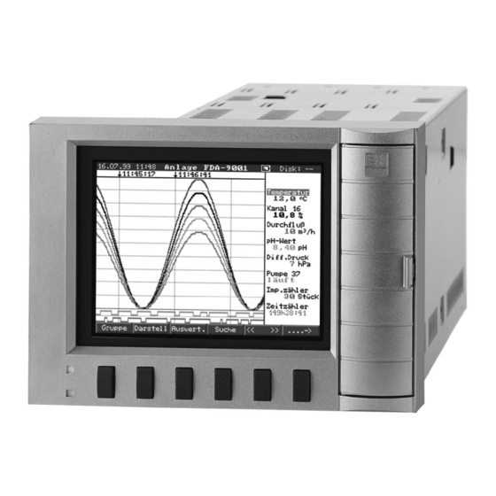
6. Handling in operation 6. Handling in operation 1.Colour screen 2.Header 3.Diskette memory display 4.Operating push buttons 5.Softkeys 6.Function LED´s 7.Diskette drive door 8.Diskette/ATA-Flash drive 9.Diskette/ATA flash card release lever 10.Write LED for data carrier Diskette ATA-Flashdisk drive Function keys/softkeys in normal operation Individual functions of the push buttons are displayed on the screen in windows directly above the respective push button: - Further push button functions can be selected by operating “..ð”... - Page 38 6. Handling in operation Group: Selection of measurement point group to be displayed. - Measurement point (analogue and digital) can be combined into groups (see “Set up - make groups”). This makes fast access to plant areas/ signals that need to be displayed together possible. - All relevant measurement points are seen together (e.g.
- Page 39 6. Handling in operation Digital display: The channels are shown as digital value displays on screen. The selected zoom range is displayed in grey. Events: Lists the last 30 alarm conditions and power failures. The required event can be high- lighted (using the arrow push buttons “Enter”), then the memory is searched if found the event is then displayed in...
- Page 40 6. Handling in operation < > (Memory page forwards/ backwards): Enables paging within the internal memory. - Displays the history of the signal sequence of the measurement points. - By changing the time base (“Select time base”) the time axis can be compressed up to 5 times.
- Page 41 6. Handling in operation Text: Possibility to enter text during operation, this text will be stored in the ring memory as well as the events list. For example text to describe the actual situation on plant can be entered. This rext will be stored including an actual time stamp.
-
Page 42: Functions Of The Leds
6. Handling in operation Memory information Information regarding size and availability of the internal memory and the changeable data carrier. Indicates the maximum time the memory will last at the actual unit settings. Hint: The memory information takes the actual unit settings into account (see “Technical information - memory”) If changes have just been made that have not been stored, the... -
Page 43: Serial Interface/Modem/Ethernet
6. Handling in operation Hint: • Always use formatted labelled diskettes. • All data on diskette is overwritten once it has been placed into the unit. • In normal operation the amount of diskette memory used is displayed in the top right hand corner of the screen (“Disk: xx %”... -
Page 44: Setting Up A Modem Link
7. Serial interfaces/Modem Operation mode “Monitor”: A Master (e.g. available computer system) interrogates the connected slaves without influencing the system. The measured data of the slaves is analysed. For this the setting of the slave address and data format for each channel is required (see “Set up - analogue inputs - channel xx - PROFIBUS DP”). -
Page 45: Ethernet Connection (Tcp/Ip)
7. Serial interfaces/Modem In the delivered PC software select “Unit - Display/change unit settings/create new unit” - Select unit, select serial connection (COM, Baudrate, number of data bits, parity) - Activate modem operation - Set up modem - Set up dial selection, line number and telephone number for the selected unit. - OK In principle, all devices equipped with an internal Ethernet interface can be integrated 7.5 Ethernet connection... - Page 46 7. Serial interfaces/Modem Menu: SETUP - Miscellaneous All parameters that affect the device’s operating system are configured in the setup - miscellaneous menu. The system parameters are input in the RS232 / Ethernet menu Hint: This menu only appears if the device is equipped with an internal Ethernet interface MAC address...
- Page 47 7. Serial interfaces/Modem Hint: Changes to the system parameters are not activated until the SETUP menu is closed and the settings accepted. Only then the device will work with the new settings. After the device has been configured and connected to the PC network, a connection Communication in the to one of the PCs in the network can be established.
-
Page 48: For Experienced Users: Serial Interface Rs 232/Rs422/Rs 485 Transmission Protocols
8. For experienced users: Serial interface RS 232/RS 422/RS 485 transmission protocols 8. For experienced users: Serial interface RS 232/RS 422/RS 485 transmission protocols General Data bits: 8 Parity: even, odd, mark, space Stop bits: 1, 2 Protocol: SOH Unit address STX Message ETX BCC Unit address: ‘0’’0’..’9‘’9’... - Page 49 8. For experienced users: Serial interface RS 232/RS 422/RS 485 transmission protocols CODE-Open command (CO) The serial operation is opened with the CO command. (Compare to code input on hand operation). This command must always precede the first WRITE command! Answer codes: 0..2: o.k.
-
Page 50: Command For Measured Data Read Out And Delete
8. For experienced users: Serial interface RS 232/RS 422/RS 485 transmission protocols Using the W command the operating parameters transmitted are the same as shown in the display. Attention: After the last WRITE command a CODE-CLOSE (CC) command must be transmitted.! Example for changing the time of the screen saver: To unit: SOH 01 STX W12E0 0010 ETX BCC... -
Page 51: Read Out Configuration Data (Dk)
8. For experienced users: Serial interface RS 232/RS 422/RS 485 transmission protocols Data restore command (DR) This command delivers all measured data stored in the memory. For further details see the data read out command (DA). Data delete (DD) This command deletes data from the measured data memory. It is to be used after the DA command when all data has been correctly received by the PC. -
Page 52: Read Out Actual Process Data
8. For experienced users: Serial interface RS 232/RS 422/RS 485 transmission protocols 8.4 Read out actual Process data is read out using the read command followed by an ASCII zero (R0): process data R0bcd Channel number (1..9, A..Z) Channel type (0=analogue (or BUS), 1=mathematic analogue, 2=digital) Type of measured value: instantaneous value Answer: Answer code measured value... -
Page 53: Technical Data
9. Technical data 9. Technical data Measurement component Reference conditions Power supply Nominal voltage: U = 115 to 230 V +10%,-15%, 50/60 Hz Warm up time > hour Ambient 25 °C +/- 5 °C temperature Humidity 55 +/- 10 % r. h. Presettable measurement ranges per channel: 4...20 mA / 1 µA (with switchable cable open circuit monitor <... - Page 54 9. Technical data Technical data Maximum (continued) allowable Channel to channel: DC 60 V, AC 60 Vp (only safe low voltages) potential Channel to Ground: AC60 Vp (only safe low voltages) difference Presettable time constant: 0...999.9 Seconds, per analogue Damping input, System base damping: can be ignored Influence effects To EN 60654-1:B1 (10% to 75% rh without condensation)
- Page 55 9. Technical data Technical data Data security (continued) 1s/2s/3s/5s/10s/15s/30s/1min/2min/3min/6min ≥ 4 year buffer for programme/measured value memory Selectable (internal memory chip: 1024 k / 2048 k, SRAM) using integrated Memory memory-cycle lithium battery (operational life cycle approx. 6 years).Cyclic per group copy of measured data for archiving onto 3 1/2", 1.44 MB (standard or diskette or ATA-flash memory-card (max.
- Page 56 9. Technical data ATA flash card 32 MB Storage Storage Storage Storage Storage Analogue cycle 6 min. cycle 1 min. cycle 30 s cycle 10 s cycle 1 s inputs 22752 days, 3792 days, 1896 days, 63 days, 632 days 19 h 11376 days, 1896 days,...
- Page 57 9. Technical data Technical data EN 61010-1, class I, overvoltage category II Safety (continued) Environment < 2000 m altitude Electrical safety Installation depth: approx. 211 mm incl. terminals, panel cut-out: x 138 Housing/installation Panel thickness: 2...40 mm, Fixing to DIN 43834 stainless steel casing, weight approx.
- Page 58 9. Technical data Technical data Physical peak: (continued) RS 485, Cable length 1000 m screened cable Baudrate: 93.75 kBaud, fixed, alternatively 45.5 kBaud PROFIBUS DP Function ”Bus-monitor" (no influence on the PROFIBUS system) connection, as with conventionally connected components: operation as Presettable slave address data format (DP/V1 formats): Integer Monitor 8, Integer 16, Integer 32, Unsigned 8, Unsigned 16, Unsigned...
- Page 59 Endress+Hauser...
- Page 60 Tel. (09) 8 35 70 90, Fax (09) 8 35 06 19 ❑ Endress+Hauser Ges.m.b.H. Wien Poland Chile Japan ❑ Endress+Hauser Polska Sp. z o.o. ❑ Endress+Hauser Chile Ltd. ❑ Sakura Endress Co. Ltd. Tel. (01) 8 80 56-0, Fax (01) 8 80 56-335 Wroclaw Santiago...