Table of Contents
Advertisement
Quick Links
Advertisement
Table of Contents
Troubleshooting

Related Manuals for Bosch Rexroth WGM


Summary of Contents for Bosch Rexroth WGM
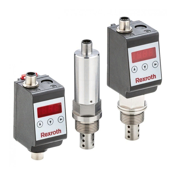
- Page 1 Oil humidity sensor WGM Operating instructions English RE 51550-B/09.2019...
- Page 2 Our products are subject to a natural process of wear and aging. © All rights with Bosch Rexroth AG, also in case of applications for industrial property protection. It may not be reproduced or given to third parties without consent of Bosch Rexroth AG.
-
Page 3: Table Of Contents
5.1.7.2 Switching output x: Upper switching limit (switching point) 5.1.7.3 Switching output x: Lower switching limit (switch-back point) 5.1.7.4 Switching output x: Switch-on delay 5.1.7.5 Switching output x: Switch-back delay 5.1.7.6 Switching output x: Testing the switching output 5.1.7.7 Change display function of the status LED RE 51550-B/09.2019, Bosch Rexroth AG... - Page 4 General technical data Technical data WGM-B Technical data WGM-R / WGM-D Outputs WGM-B Outputs WGM-R / WGM-D Pin assignment WGM-B Pin assignment WGM-R / WGM-D Indication ranges Current settings 9.10 Overview menu sequence Appendix: EU Declaration of Conformity Bosch Rexroth AG, RE 51550-B/09.2019...
-
Page 5: Introduction
The sensor options offer the possibility of an analog output of the relative humidity. The threshold value of the switching point is pre-set and can only be configured ex works or via the digital interface. RE 51550-B/09.2019, Bosch Rexroth AG... -
Page 6: Temperature Monitoring
The sensor options are available with a digital interface. Here, the sensor uses the standardized technology IO-Link, a powerful point-to-point communication. It is based on the previous and proven connection technology. Compatibility with the previous technology is guaranteed. Bosch Rexroth AG, RE 51550-B/09.2019... -
Page 7: Type Key
Connecting cable Connecting cable for remote Sensor without display WGM-B-1X/2A1S-G34-V R928057041 R928058031 – WGM-B-1X/1D0S-G34-V R928057042 R928058030 – Sensor with display WGM-D-1X/2A2S-G34-V R928057045 R928058031 – WGM-D-1X/1D1S-G34-V R928057046 R928058030 – Remote display WGM-R-1X/2A2S-0-0 R928057043 R928058031 R928058029 WGM-R-1X/1D1S-0-0 R928057044 R928058030 R928058029 RE 51550-B/09.2019, Bosch Rexroth AG... -
Page 8: Scope Of Delivery
Indicates a dangerous situation which may cause death or WARNING severe injury if not avoided. Indicates a dangerous situation which may cause minor or CAUTION medium personal injury if not avoided. NOTICE Damage to property: The product or the environment could be damaged. Bosch Rexroth AG, RE 51550-B/09.2019... -
Page 9: Warning Signs And Symbols
Warning – Inhalation hazard: toxic gas Warning – Corrosive liquids General information Disconnect mains plug Wear respiratory protection Wear face shield Wear gloves If this information is not observed, the product cannot be used and/or operated optimally. ▶ Individual, independent action RE 51550-B/09.2019, Bosch Rexroth AG... -
Page 10: Safety Instructions
Bosch Rexroth AG accepts no liability for unauthorized modifications to the device, ▶... -
Page 11: Transport And Storage
The products should only be transported in their original packaging or a suitable replacement. When not in use, the operating equipment must be protected against humidity and heat. They must be kept in a covered, dry and dust-free room at room temperature. RE 51550-B/09.2019, Bosch Rexroth AG... -
Page 12: Set-Up And Connection
When connecting the devices, the maximum admissible voltages and currents (see technical data) must be observed and the required wire cross-sections and circuit breakers must be dimensioned accordingly. When selecting the connecting cables, the maximum admissible operating temperatures of the devices must also be observed. Bosch Rexroth AG, RE 51550-B/09.2019... -
Page 13: Installation Recommendations
Fig. 1: Circuitry of switching outputs Notice: When measuring the switching output with high-impedance measuring device inputs or using it as a frequency output, a 10 kΩ resistor must be connected between the output and the ground (GND) to prevent incorrect measurements. RE 51550-B/09.2019, Bosch Rexroth AG... -
Page 14: Operation
Description 2 switching outputs LED 1 - yellow Humidity Status switching output 1 LED 2 - red Temperature Status switching output 2 The switching behavior of the LEDs (illuminated with closed or open switching contact) can be changed. Bosch Rexroth AG, RE 51550-B/09.2019... -
Page 15: General Key Functions
▶ Exit the submenu by selecting the EXIT menu item and confirming with the key. The device returns to the superior menu or to the measured value display. RE 51550-B/09.2019, Bosch Rexroth AG... -
Page 16: Active Key Lock
Here the 4 digits mean tsav: t: Type h= humidity and temperature measurement 2 or 4 s: Number of switching outputs 0 or 2 a: Number of analog outputs i = standard assembly (tank installation) v: Assembly type of the device r = remote installation Bosch Rexroth AG, RE 51550-B/09.2019... - Page 17 The structure of the main menus Humidity ( ) and Temperature ( ) is hUMi TeMp identical. The settings for the switching outputs or the analog outputs (if available) are made here. RE 51550-B/09.2019, Bosch Rexroth AG...
-
Page 18: Changing The Basic Settings
Before using this option, check the hazard potential within your process. Bosch Rexroth AG is not liable for any health or material damage that may occur as a result of this setting. - Page 19 Version with 2 switching outputs: Switching outputs Basic settings h.UNI 55 c T.UNI .OUi hUMi .OU2 TeMp fasT Version with analog outputs: Analog outputs ai.hI ai.lO a.OUi a2.hI a2.lO a.OU2 Diagnostic settings: Diagnosis sj.OU OUTi Dh.MM DT.MM RE 51550-B/09.2019, Bosch Rexroth AG...
-
Page 20: Switching Off The Normal Troubleshooting
Here the displayed unit symbol for the temperature is defined: The following options are available: Degrees Degrees Celsius Fahrenheit Notice: The measured value conversion and the adjustment of the measurement range take place automatically. Nevertheless, the corresponding switching and switch-back points must be checked. Bosch Rexroth AG, RE 51550-B/09.2019... -
Page 21: Defining The Switching Outputs
The update rate of the display can be set depending on the application. The display can also be switched off completely. The function of the LED remains unchanged. The following options are available: quick medium slow display off Notice: Error messages are displayed even if the display is switched off. RE 51550-B/09.2019, Bosch Rexroth AG... -
Page 22: Activate / Deactivate Key Lock
Basic settings advanced functions. In the submenu Advanced functions, further settings can be made for each individual switching output that e.g. influence the switching behavior of the output. Testing the output is also possible here. Bosch Rexroth AG, RE 51550-B/09.2019... -
Page 23: Switching Output X: Definition Of The Switching Characteristic
T and frequency f: 1 Hz and 100 Hz is output proportional to the measured value. Notice: To increase the edge steepness of the rectangular signal, it is recommended to fit the switching output with a 10 kΩ resistor. RE 51550-B/09.2019, Bosch Rexroth AG... -
Page 24: Switching Output X: Upper Switching Limit (Switching Point)
If the switching output OUT x has been assigned the window function, is displayed. The set value corresponds to the lower window limit. If the switching output OUT x has been assigned the frequency ▶ output function, is displayed. The set value corresponds to the frequency 1 Hz. Bosch Rexroth AG, RE 51550-B/09.2019... -
Page 25: Switching Output X: Switch-On Delay
If the switching output OUT x has been assigned the window function, the set value corresponds to the switch-on delay which detects a valid leaving of the measuring window. If the switching output OUT x has been assigned the frequency ▶ output function, this value has no effect. RE 51550-B/09.2019, Bosch Rexroth AG... -
Page 26: Switching Output X: Testing The Switching Output
It is possible that the logic function of the display shall be different from the physical signal on the switching output. You can therefore also reverse this display in this menu item (switching output open - LED illuminated). Bosch Rexroth AG, RE 51550-B/09.2019... -
Page 27: Analog Outputs
Setting range: 0% to 100% Notice: ▶ The set output range must not be smaller than 10% of the measurement range: > = 10% * ( ai.hI ai.lO ▶ If the selected range is too small, the analog value output may have increments. RE 51550-B/09.2019, Bosch Rexroth AG... -
Page 28: Analog Output X: Assignment Of The Lower Limit
Setting range: -20 °C to 120 °C [-4 °F to 248 °F] Notice: ▶ The set output range must not be smaller than 10% of the measurement range: > = 10% ai.hI ai.lO ▶ If the selected range is too small, the analog value output may have increments. Bosch Rexroth AG, RE 51550-B/09.2019... -
Page 29: Analog Output X: Determining The Signal Type
Open the menu with the u key. Now you can change or call up the diagnosis settings. Important notice: Only one switching output can be logged. The switching output to be logged is selected in the menu item Set Journal Out ( sj.OU RE 51550-B/09.2019, Bosch Rexroth AG... -
Page 30: Calling The Log Book
If an error occurs, the error number is displayed here (see table in chapter Troubleshooting and remedy [> page 35]). Press the u key to return to the submenu or use q to select the display Confirm the display with the u key to reset the error messages. Bosch Rexroth AG, RE 51550-B/09.2019... -
Page 31: Maximum And Minimum Humidity
, key p; u = delete Press the u key to return to the submenu or use q, p to select the next log entry. Pressing the u key to confirm the display clears the event list and returns to the submenu. RE 51550-B/09.2019, Bosch Rexroth AG... -
Page 32: Defining The Switching Output To Be Logged
The following options are available: Setting range: 0…100 seconds ▶ Open the value list with the u key. ▶ Set the value with the q and p keys and confirm with the ukey (e.g. 5 seconds). The device returns to the submenu. Bosch Rexroth AG, RE 51550-B/09.2019... -
Page 33: Wgm-B
By default, the relative humidity is represented at the analog output from 0% to 100%. The temperature is represented at the analog output from -20 °C to 120 °C. RE 51550-B/09.2019, Bosch Rexroth AG... -
Page 34: Maintenance And Cleaning
In case an error occurs during operation, this chapter contains information on troubleshooting and remedy. Repair works on the operating equipment may only be carried out by personnel authorized by Bosch Rexroth AG. If you have any questions, please contact our service department:... -
Page 35: Troubleshooting And Remedy
Load too high Reduce load to admissible value (current output) Analog output does not Incorrect configuration In the submenu caNx change the output of the analog output "Testing the analog output", signal with changed input ensure normal operation signal RE 51550-B/09.2019, Bosch Rexroth AG... -
Page 36: Disposal
-20 °C to + 80 °C Threaded connection G 3/4" pipe thread, Eolastic seal Max. tightening torque 20 Nm Sensor length from sealing 36 mm surface Max. flow velocity at sensor 5 m/s Media resistance Fluids based on mineral oil (other fluids on request) Bosch Rexroth AG, RE 51550-B/09.2019... -
Page 37: Technical Data Wgm-B
Permanently set to 80% relative humidity Switching current max. 0.2 A Others on request Temperature measurement Measurement range -20 °C to +120 °C Accuracy ± 1.5 % FS Analog output 4 - 20 mA (-20 to +120 °C) Tolerance ± 0.5% FS Load Ω = (U - 8 V) / 0.02 A RE 51550-B/09.2019, Bosch Rexroth AG... -
Page 38: Technical Data Wgm-R / Wgm-D
IP65* (display) * with fitted plug-in connector Ø 16 G 3/4 IO-Link IO-Link Revision 1.1 Baud rate COM3 (230.4 k) SIO mode Min. cycle time 10 ms Humidity measurement Measurement range 0 - 100% rel. humidity Accuracy ± 3 % FS Bosch Rexroth AG, RE 51550-B/09.2019... -
Page 39: Outputs Wgm-B
9.5 Outputs WGM-R / WGM-D Version 2A2S 1D1S Connector (base) 1 x M12 – 8-pin 1 x M12 – 4-pin Display & remote Sensor connection 1 x M12 – 8-pin 1 x M12 – 8-pin socket (bottom) remote Switching outputs IO-Link Analog output for humidity Analog output for temperature RE 51550-B/09.2019, Bosch Rexroth AG... -
Page 40: Pin Assignment Wgm-B
9.7 Pin assignment WGM-R / WGM-D Connector A Sensor connection socket WGM-D/ WGM-R WGM-D/ WGM-R WGM-R 2A2S 1D1S Male/female connector 8-pin 4-pin 8-pin Standard IO-Link DO/S2 S1 humidity I2 temp. I1 humidity I1 humidity I2 temp. I2 temp. Bosch Rexroth AG, RE 51550-B/09.2019... -
Page 41: Indication Ranges
Humidity Percent – -100% 999% Temperature °C -100 °C 999 °C °F -100 °F 999 °F 9.9 Current settings Switching outputs Basic settings Diagnosis sj.OU h.UNI Dh.MM T.UNI DT.MM .OUi .OU2 .OU3 .OU4 Analog outputs ai.hI ai.lO a.OUi a2.hI a2.lO a.OU2 RE 51550-B/09.2019, Bosch Rexroth AG... -
Page 42: Overview Menu Sequence
____ HuMi- tEMP ____ di 5 ____ FASt - off FASt Medi ____ 0 - 999 di A Bosch Rexroth AG, RE 51550-B/09.2019 ____ J . o ut ____ Jor I - --- JorX ____ J . E r r ____ E___ ____ H. - Page 43 ____ _ ; _ ____ t . M M ____ _ ; _ ____ SJ . o u out _ Out1 - Out_ ____ DH. M M 0 - 100 ____ dt . M M 0 - 100 RE 51550-B/09.2019, Bosch Rexroth AG...
- Page 44 Bosch Rexroth AG, RE 51550-B/09.2019...
- Page 45 45/46 RE 51550-B/09.2019, Bosch Rexroth AG...
- Page 46 Bosch Rexroth AG Zum Eisengießer 1 97816 Lohr a. Main Germany Phone +49 (0) 9352 18-0 info@boschrexroth.de www.boschrexroth.com Subject to change without notice Printed in Germany RE 51550-B/06.2019...