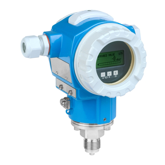
Endress+Hauser Cerabar S PMC71 Functional Safety Manual
Process pressure and level measurement with 4-20 ma output signal
Hide thumbs
Also See for Cerabar S PMC71:
- Operating instructions manual (238 pages) ,
- Technical information (136 pages) ,
- Manual (96 pages)

Related Manuals for Endress+Hauser Cerabar S PMC71


Summary of Contents for Endress+Hauser Cerabar S PMC71
- Page 1 Products Solutions Services SD00190P/00/EN/16.17 71385812 Special Documentation Cerabar S PMC71, PMP71, PMP75 Functional Safety Manual Process pressure and level measurement with 4-20 mA output signal...
-
Page 2: Table Of Contents
"Pressure" operating mode ......37 Form for standard device configuration - Pressure . 41 Form for standard device configuration - Level ..43 Endress+Hauser... -
Page 3: Sil Declaration Of Conformity
Cerabar S SIL Declaration of Conformity The binding document forms part of the scope of delivery when the Cerabar S is ordered with the "SIL 2/ SIL 3 IEC 61508 Declaration of Conformity" option. SIL_Cerabar S Endress+Hauser... -
Page 4: Safety-Related Parameters
If the average temperature during continuous operation is in the region of +50 °C (+122 °F), a factor of 1.3 should be taken into account. During this time, all diagnostic functions are executed at least once. Time between fault detection and fault reaction. Step response time as per DIN EN 61298-2. Endress+Hauser... - Page 5 If the average temperature during continuous operation is in the region of +50 °C (+122 °F), a factor of 1.3 should be taken into account. During this time, all diagnostic functions are executed at least once. Time between fault detection and fault reaction. Step response time as per DIN EN 61298-2. Endress+Hauser...
- Page 6 If the average temperature during continuous operation is in the region of +50 °C (+122 °F), a factor of 1.3 should be taken into account. During this time, all diagnostic functions are executed at least once. Time between fault detection and fault reaction. Step response time as per DIN EN 61298-2. Endress+Hauser...
- Page 7 If the average temperature during continuous operation is in the region of +50 °C (+122 °F), a factor of 1.3 should be taken into account. During this time, all diagnostic functions are executed at least once. Time between fault detection and fault reaction. Step response time as per DIN EN 61298-2. Endress+Hauser...
- Page 8 If the average temperature during continuous operation is in the region of +50 °C (+122 °F), a factor of 1.3 should be taken into account. During this time, all diagnostic functions are executed at least once. Time between fault detection and fault reaction. Step response time as per DIN EN 61298-2. Endress+Hauser...
- Page 9 If the average temperature during continuous operation is in the region of +50 °C (+122 °F), a factor of 1.3 should be taken into account. During this time, all diagnostic functions are executed at least once. Time between fault detection and fault reaction. Step response time as per DIN EN 61298-2. Endress+Hauser...
- Page 10 If the average temperature during continuous operation is in the region of +50 °C (+122 °F), a factor of 1.3 should be taken into account. During this time, all diagnostic functions are executed at least once. Time between fault detection and fault reaction. Step response time as per DIN EN 61298-2. Endress+Hauser...
- Page 11 If the average temperature during continuous operation is in the region of +50 °C (+122 °F), a factor of 1.3 should be taken into account. During this time, all diagnostic functions are executed at least once. Time between fault detection and fault reaction. Step response time as per DIN EN 61298-2. Endress+Hauser...
- Page 12 If the average temperature during continuous operation is in the region of +50 °C (+122 °F), a factor of 1.3 should be taken into account. During this time, all diagnostic functions are executed at least once. Time between fault detection and fault reaction. Step response time as per DIN EN 61298-2. Endress+Hauser...
-
Page 13: Useful Lifetime Of Electric Components
The established failure rates of electrical components apply within the useful lifetime as per IEC components 61508-2: 2010 section 7.4.9.5 note 3. According to DIN EN 61508-2:2011 section 7.4.9.5 national footnote N3 appropriate measures taken by the manufacturer and operator can extend the useful lifetime. Endress+Hauser... -
Page 14: Certificate
Cerabar S Certificate TUEV_EN Endress+Hauser... -
Page 15: General Information
The document is part of the Operating Instructions and serves as a reference for application-specific parameters and notes. • General information about functional safety: SIL • General information about SIL is available: In the Download Area of the Endress+Hauser Internet site: www.de.endress.com Search Functional safety Symbols used Safety symbols... -
Page 16: Supplementary Device Documentation
Control Drawings or instructions for devices suitable for use in approval by means of feature 10 Certificates hazardous areas or as overfill prevention "Approval" in the order code. (German Water Resources Act). The corresponding documentation is provided with the device. Endress+Hauser... -
Page 17: Permitted Device Types
In the event of device modifications, a modification process compliant with IEC 61508 is applied. Devices with a firmware version 02.0x and higher which are already in use can still be operated if the suitable DTM or DD is used. Endress+Hauser... -
Page 18: Sil Label On The Nameplate
The operator is responsible for assessing the suitability of the overall system, consisting of the basic device and the diaphragm seal, for safety-related operation. ‣ Observe the Technical Information ("Supplementary device documentation", ä 16) SIL label on the nameplate SIL certified devices bear the following symbol on the nameplate: Endress+Hauser... -
Page 19: Safety Function
(MTTR) of 8 hours. Safety-related Explanation Implications for the Implications for error safety-related measuring uncertainty (position, see Fig. ä 20) output signal No device error Safe: SD None 1 Is within the specification No error (see TI, BA, ...) Endress+Hauser... - Page 20 C LO-Alarm ≤ 3.6 mA Dangerous undetected failures in this scenario An incorrect output signal that deviates from the real measured value by more than 1%, but is still in the 4-20 mA range, is considered a dangerous, undetected failure. Endress+Hauser...
-
Page 21: Use In Protective Systems
Do not use the SAFETY CONFIRM. sequence if the device is operated outside the set current or measuring range in applications. ‣ Standard device configuration and software/hardware locking is recommended in such applications. The error codes are listed in the Operating Instructions. Endress+Hauser... - Page 22 (3.8to20.5 mA) Process pressure/current above set range limit E620 > URV E115 (URL +10 %) Process pressure above sensor measuring range limit E727 (>> URL +10 %) The output current depends on the message setting as alarm or warning. Endress+Hauser...
-
Page 23: Confirmation And Locking Methods
Do not use the SAFETY CONFIRM. sequence if the device is operated outside the set current or measuring range in applications, Table ä 22. Configuring E727 as a warning or alarm affects the SIL parameters, Table ä 4 ff. Endress+Hauser... -
Page 24: Field Communicator Or Fieldcare/Devicecare
MEASURING MODE PRESSURE EMPTY BASIC SETUP EMPTY CALIB. BASIC SETUP PRESSURE FULL BASIC SETUP FULL CALIB. BASIC SETUP SET LRV BASIC SETUP SET URV BASIC SETUP DAMPING VALUE BASIC SETUP OUTPUT FAIL MODE OUTPUT SET MIN. CURRENT OUTPUT Endress+Hauser... - Page 25 If reset correctly, the OUTPUT CURRENT parameter displays "LinMaxNorm/22/3.8/0s". Factory values: – CURR. CHARACT.: linear – OUTPUT FAIL MODE: max. alarm – ALT. CURR. OUTPUT: normal – SET MAX. ALARM: 22 mA – SET MIN. CURRENT: 3.8 mA – ALARM DELAY: 0.0 s Endress+Hauser...
- Page 26 CONF. PASSWORD parameter. Afterwards, the device is locked for the safe measuring mode. The SAFETY LOCK parameter displays the status "Locked". This locking has the highest priority and can only be disabled via the SAFETY LOCK and SAFETY PASSWORD parameters. ä 31, "Locking/unlocking" section. Endress+Hauser...
- Page 27 "Form for device configuration" ( ä 41ff). The "Offline" operating option is not allowed for functional safety applications. Make sure that no messages such as "Device disconnected" occur during the configuration. Endress+Hauser...
-
Page 28: Standard Device Configuration Via Onsite Display, Field Communicator Or Fieldcare/Devicecare
Read out the specified parameters and compare them to the "Form for device configuration" ä 41ff. Lock the device via software and/or hardware. Operating Instructions BA00271P/00/EN, section "Locking/unlocking operation". Read out and log the CONFIG. COUNTER parameter. Menu path: (GROUP SELECTION ) OPERATING MENU TRANSMITTER INFO TRANSMITTER DATA Endress+Hauser... -
Page 29: Conditions For Safe Measuring Mode
CALIBRATION MODE parameter. You can read out the corresponding values for the PRESSURE EMPTY and PRESSURE FULL parameters here. • The sensor can only be recalibrated by Endress+Hauser Service. All parameters, except the parameters for a sensor recalibration, are reset with the "7864"... - Page 30 • When operating via the DTM, locking via the SAFETY LOCK menu is only possible in the online mode. • The sensor can only be recalibrated by Endress+Hauser Service. All parameters, except the parameters for a sensor recalibration, are reset with the "7864"...
-
Page 31: Checks
They differ in terms of the percentage rate of detection. If the device has assumed a fault condition, i.e. an alarm is output and the current output assumes the set value, the cause of the fault must first be eliminated. Endress+Hauser... - Page 32 After this procedure, the current value is output correctly. The value displayed, e.g. on the onsite display, and the digital value via HART can deviate from the pressure actually present. If the dis- play value and digital value are also to be corrected, please contact Endress+Hauser Service. Endress+Hauser...
-
Page 33: Life Cycle
Repair Repair means a one-to-one replacement of components. Repairs on the devices must always be carried out by Endress+Hauser. Safety functions cannot be guaranteed if repairs are carried out by anybody else. Exceptions:... -
Page 34: Modification
The replaced component must be sent to Endress+Hauser for the purpose of fault analysis if the device has been operated in a protective system. In the event of the failure of a SIL-labeled Endress+Hauser device that has been operated in a protective function, the "Declaration of Contamination and Cleaning" with the corresponding note "Used as SIL device in protective system"... -
Page 35: Appendix
Safety Manual version Changes Valid from firmware Valid from version hardware version SD00190P/00/EN/10.04 First edition 02.00 02.00 SD00190P/00/EN/07.06 New FW 02.10 02.00 02.00 SD00190P/00/EN/04.08 SW version with SIL3 02.00 02.00 changes regarding 700 bar SD00190P/00/EN/13.13 New FW 02.11 02.00 02.00 Endress+Hauser... - Page 36 Cerabar S Safety Manual version Changes Valid from firmware Valid from version hardware version SD00190P/00/EN/14.13 New FW 02.20 02.00 02.00 SD00190P/00/EN/15.16 Edition 2 02.00 02.00 SD00190P/00/EN/16.17 New FW 02.30.zz 02.00 02.00 Endress+Hauser...
-
Page 37: Parameter Description
• Valid: Select this option if the factory values displayed correspond to the desired values. • Not valid: Select this option if the factory values displayed do not correspond to the desired values. In this case, operation of the device in the safe measuring mode is not possible. Endress+Hauser... - Page 38 • Valid: Select this option if the selected and desired value is displayed. • Not valid: Select this option if an incorrect value or a value that was not selected is displayed. In this case, operation of the device in the safe measuring mode is not possible. Endress+Hauser...
-
Page 39: Pressure
In this case, operation of the device in the safe measuring mode is not possible. You can also configure the lower-range value via the GET LRV parameter and a pressure present at the device. The SET LRV parameter displays the pressure value that was assigned to the lower-range value. Endress+Hauser... -
Page 40: Set Urv
Once the safety-related parameters have been successfully interrogated, the (856) password "7452" must be entered again via the CONF. PASSWORD parameter. Afterwards, the device is locked for the safe measuring mode. The SAFETY LOCKSTATE parameter displays the status "Locked". Endress+Hauser... -
Page 41: Form For Standard Device Configuration - Pressure
726 Sens. temp. error overrange Warning/ Alarm alarm 727 Sens. pres. error overrange Warning Alarm or Warning 620 Current output out of range Warning Alarm or Warning Alarm Delay 0.0 s 0.0 s Alarm Displ. Time 0.0 s 0.0 s Endress+Hauser... - Page 42 Within sensor range According to ordering specifications Depending on the "Press. Sens. Hilim (485)" parameter Alarm setting from firmware version ≥ 02.30.zz Setting influences SFF Only for software version ≥ 02.20 Onsite display and FieldCare HART handheld terminal Company: Date: Signature: Endress+Hauser...
-
Page 43: Form For Standard Device Configuration - Level
Setup (025) Output Curr. Charact. Linear Linear Output Fail Mode Max. Alarm Max. Alarm Min. Alarm Alt. Current Output Normal Normal Max. Alarm Current 22 mA 22 mA Set Min. Current 3.8 mA 3.8 mA Simulation Simulation None None Endress+Hauser... - Page 44 According to ordering specifications Depending on the "Press. Sens. Hilim (485)" parameter Alarm setting from firmware version ≥ 02.30.zz Setting in influences SFF Only for software version ≥ 02.20 Onsite display and FieldCare HART handheld terminal Company: Date: Signature: Endress+Hauser...
- Page 45 Cerabar S Endress+Hauser...
- Page 46 Cerabar S Endress+Hauser...
- Page 47 Cerabar S Endress+Hauser...
- Page 48 71385812 www.addresses.endress.com...