Endress+Hauser Cerabar S PMC71 Brief Operating Instructions
Process pressure measurement
Hide thumbs
Also See for Cerabar S PMC71:
- Operating instructions manual (238 pages) ,
- Technical information (136 pages) ,
- Manual (96 pages)
Table of Contents
Advertisement
Quick Links
KA01025P/00/EN/19.22-00
71565953
2022-04-05
Products
Brief Operating Instructions
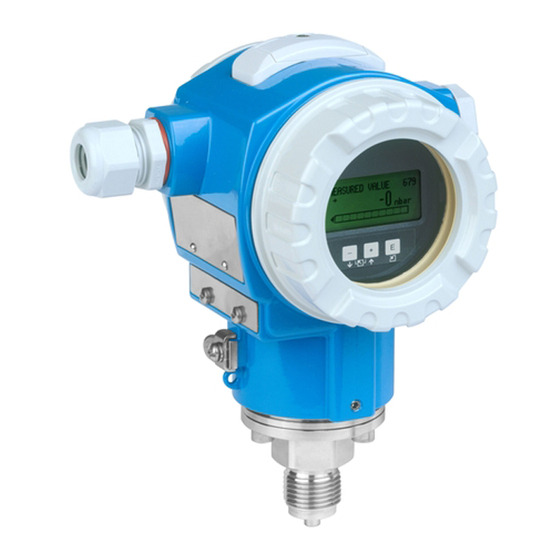
Cerabar S PMC71, PMP71,
PMP75
Process pressure measurement
These Brief Operating Instructions are not a substitute for the
Operating Instructions pertaining to the device.
Detailed information about the device can be found in the
Operating Instructions and the additional documentation.
Available for all device versions via
• Internet:
www.endress.com/deviceviewer
• Smartphone/tablet: Endress+Hauser Operations app
Solutions
Services
Advertisement
Table of Contents

Related Manuals for Endress+Hauser Cerabar S PMC71


Summary of Contents for Endress+Hauser Cerabar S PMC71
- Page 1 Services KA01025P/00/EN/19.22-00 71565953 2022-04-05 Brief Operating Instructions Cerabar S PMC71, PMP71, PMP75 Process pressure measurement These Brief Operating Instructions are not a substitute for the Operating Instructions pertaining to the device. Detailed information about the device can be found in the Operating Instructions and the additional documentation.
-
Page 2: Associated Documentation
Associated documentation Cerabar S PMC71, PMP71, PMP75 Associated documentation Order code: XXXXX-XXXXXX Ser. no.: XXXXXXXXXXXX Ext. ord. cd.: XXX.XXXX.XX Serial number www.endress.com/deviceviewer Endress+Hauser Operations App A0023555 About this document Document function The Brief Operating Instructions contain all the essential information from incoming acceptance to initial commissioning. - Page 3 Cerabar S PMC71, PMP71, PMP75 About this document Symbols 2.2.1 Safety symbols DANGER This symbol alerts you to a dangerous situation. Failure to avoid this situation will result in serious or fatal injury. WARNING This symbol alerts you to a dangerous situation. Failure to avoid this situation can result in serious or fatal injury.
-
Page 4: Registered Trademarks
The manufacturer is not liable for damage caused by improper or non-intended use. Verification for borderline cases: ‣ For special fluids and fluids for cleaning, Endress+Hauser is glad to provide assistance in verifying the corrosion resistance of fluid-wetted materials, but does not accept any warranty or liability. -
Page 5: Workplace Safety
It meets the general safety standards and legal requirements. It also complies with the EC directives listed in the device-specific EC Declaration of Conformity. Endress+Hauser confirms this by affixing the CE mark to the device. Functional safety SIL3 (optional) The Functional Safety Manual must be strictly observed for devices that are used in functional safety applications. -
Page 6: Incoming Acceptance And Product Identification
• Do the data on the nameplate correspond to the order specifications and the delivery note? • Is the documentation available? • If required (see nameplate): are the Safety Instructions (XA) provided? If one of these conditions is not fulfilled, please contact your Endress+Hauser sales office. Storage and transport 4.2.1 Storage conditions Use original packaging. -
Page 7: Mounting Requirements
Cerabar S PMC71, PMP71, PMP75 Mounting Mounting Mounting requirements 5.1.1 General installation instructions • Devices with a G 1 1/2 thread: When screwing the device into the tank, the flat seal has to be positioned on the sealing surface of the process connection. To avoid additional strain on the process membrane, the thread should never be sealed with hemp or similar materials. - Page 8 Mounting Cerabar S PMC71, PMP71, PMP75 A0031804 • Keep the pressure compensation and GORE-TEX® filter (1) free from contamination and water. • Cerabar S devices without diaphragm seals are mounted in accordance with the same guidelines as a manometer (DIN EN 837‑2). We recommend the use of shutoff devices and water pocket pipes.
- Page 9 Cerabar S PMC71, PMP71, PMP75 Mounting 5.2.1 Pressure measurement in gases Mount the Cerabar S with shutoff device above the tapping point so that any condensate can flow into the process. 5.2.2 Pressure measurement in vapors For pressure measurement in vapors, use water pocket pipes. The water pocket pipe reduces the temperature to almost ambient temperature.
-
Page 10: Electrical Connection
Electrical connection Cerabar S PMC71, PMP71, PMP75 NOTICE In order to obtain more precise measurement results and to avoid a defect in the device, mount the capillaries as follows: ‣ Mount capillaries vibration-free (in order to avoid additional pressure fluctuations) ‣... -
Page 11: Connecting The Measuring Unit
Cerabar S PMC71, PMP71, PMP75 Electrical connection A0047210 1 FOUNDATION Fieldbus electrical connection Housing Internal ground terminal External ground terminal Minimum supply voltage, for version in the non-hazardous area = 9 to 32 V DC Devices with integrated overvoltage protection are labeled "OVP" (overvoltage protection) here. - Page 12 (20 to 12 AWG) 6.2.4 Cable specification • Endress+Hauser recommends using twisted, shielded two-wire cables. • Cable diameter: 5 to 9 mm (0.2 to 0.35 in) For further information on the cable specifications, see Operating Instructions BA00013S "FOUNDATION Fieldbus Overview", FOUNDATION Fieldbus Guideline and IEC 61158-2 (MBP).
-
Page 13: Operation Options
Cerabar S PMC71, PMP71, PMP75 Operation options Operation options Operation without an operating menu Operation options Explanation Graphic Local operation without The device is operated using the operating keys and device display DIP switches on the electronic insert. Display Zero... - Page 14 Operation options Cerabar S PMC71, PMP71, PMP75 Zero S D A 0 1 2 3 4 5 6 7 8 Address A0020032 DIP switch for locking/unlocking parameters relevant to the measured value DIP switch for switching damping on/off Green LED to indicate value is accepted...
- Page 15 Cerabar S PMC71, PMP71, PMP75 Operation options display once you have started the FF configuration program and integrated the device into the network. The blocks available are displayed under the device name. If the device description has not yet been loaded, the blocks report "Unknown" or "(UNK)".
- Page 16 Operation options Cerabar S PMC71, PMP71, PMP75 – A0016498 The following table illustrates the symbols that can appear on the local display. Four symbols may appear at the same time. Symbol Meaning Alarm symbol • Symbol flashing: warning, device continues measuring •...
- Page 17 Cerabar S PMC71, PMP71, PMP75 Operation options Operating key(s) Meaning Contrast setting of local display: darker Contrast setting of local display: brighter ESC functions: • Exit the editing mode without saving the modified value • You are in the menu within a function group: the first time you press the keys simultaneously, you go back one parameter in the function group.
- Page 18 Operation options Cerabar S PMC71, PMP71, PMP75 Set URV Operation Press or to enter the edit mode. 1 0 0 . 0 0 0 mbar The first digit is highlighted in black. Use the key to change "1" to "5".
-
Page 19: Configuring Messages
Cerabar S PMC71, PMP71, PMP75 Commissioning Commissioning The device is configured for the "Pressure" measuring mode as standard. The measuring range and the unit in which the measured value is transmitted correspond to the data on the nameplate. WARNING The permitted process pressure is exceeded! Risk of injury if parts burst! Warnings are displayed if the pressure is too high ‣... - Page 20 Commissioning Cerabar S PMC71, PMP71, PMP75 • Menu path on local display: GROUP SELECTION → OPERATING MENU → SETTINGS → POSITION ADJUST. • Menu path in FieldCare: OPERATING MENU → SETTINGS → POSITION ADJUST Endress+Hauser...
- Page 21 Cerabar S PMC71, PMP71, PMP75 Commissioning 8.3.1 Performing position adjustment via the local display or FieldCare The parameters listed in the following table can be found in the POSITION ADJUST. group (menu path: OPERATING MENU → SETTINGS → POSITION ADJUST).
- Page 22 Commissioning Cerabar S PMC71, PMP71, PMP75 Quick Setup menu for the "Pressure" measuring mode Local operation FieldCare Measured value display Measured value display Switch from the measured value display to the GROUP Select the QUICK SETUP menu. SELECTION with .
- Page 24 *71565953* 71565953 www.addresses.endress.com...