Table of Contents
Advertisement
Quick Links
Advertisement
Table of Contents

Related Manuals for CDA HG9321SS


Summary of Contents for CDA HG9321SS
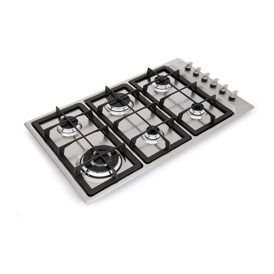
- Page 1 HG9321SS Built-in Cooking Hob Installation, Use and Maintenance www.cda.eu...
-
Page 2: Declaration Of Ce Conformity
The CDA Group Ltd cannot be held responsible for injuries or losses caused by incorrect use or installation of this product. Please note that CDA reserve the right to invalidate the guarantee supplied with this product following incorrect installation or misuse of the appliance. -
Page 3: Important Safety Precautions And Recommendations
IMPORTANT SAFETY PRECAUTIONS AND RECOMMENDATIONS IMPORTANT: This appliance is designed and manufactured solely for the cooking of domestic (household) food and is not suitable for any non domestic application and therefore should not be used in a commercial environment. The appliance guarantee will be void if the appliance is used within a non domestic environment i.e. - Page 4 CAUTION: this appIiance must only be installed in a permanently • ventilated room in compliance with the applicable regulations. Do not carry out cleaning or maintenance operations on the appliance • without having previously disconnected it from the electric power supply.
- Page 5 WARNING: Unattended cooking on a hob with fat or oil can be • dangerous and may result in fire. NEVER try to extinguish a fire with water, but switch off the appliance and then cover flame e.g. with a lid or a fire blanket.
- Page 7 ADVICE ADVICE for the for the INSTALLER INSTALLER...
-
Page 8: Tips For Installation
TIPS FOR INSTALLATION Location – The appliance may be installed in a kitchen, Kitchen/diner or a bed sitting room, but not in a room or space containing a bath or a shower. – The appliance must not be installed in a bed-sit room of less than 20m 3 . –... -
Page 9: Installation
Installation Technical Information for the Installer In order to install the hob into the kitchen fixture, a hole with the dimensions shown in fig. 1 has to be made, bearing in mind the following: – within the unit, between the bottom of the hob and the upper surface of a shelf there must be a clearance of at least 30 mm. - Page 10 Fastening the Installation Brackets (fig. 4) • Each hob is provided with an installation kit including brackets and screws for fastening the top to fixture panels from 2 to 4 cm thick. • Turn the hob upside down and fasten the brackets “A” to the appropriate socket holes, without tightening the screws “B”...
-
Page 11: Provision For Ventilation
PROVISION FOR VENTILATION The appliance should be installed into a room or space with an air supply in accordance with • the current version of BS 5440-2: 2000. For rooms with a volume of less than 5m - permanent ventilation of 100 cm free area must •... -
Page 12: Gas Supply Requirements
Gas supply requirements Important Note This appliance is supplied for use on NATURAL GAS or LPG (check the gas regulation label attached on the appliance). • Appliances supplied for use on NATURAL GAS: they are adjusted for this gas only and cannot be used on any other gas (LPG) without modification. -
Page 13: Gas Connection
37 mbar is required. The installation must conform to the relevant British Standards. CDA are not legally able to provide any assistance in the installation of gas appliances except to suitably qualified and registered installers. Any suitably qualified and registered fitter requiring help must provide name, address and registration number. - Page 14 Gas connection Cat: II 2H3+ The fitting (fig. 6) is made up of: – 1 nut “A” – 1 elbow fitting “C” – gasket “F” Connection to the Gas Supply – Be careful when flexible pipes are used that they do not come into contact with moving parts. –...
-
Page 15: Lubrication Of The Gas Taps
GAS MAINTENANCE TABLE FOR THE CHOICE OF THE INJECTORS G30/G31 Cat: II 2H 3+ 28-30/37 mbar 20 mbar Nominal Reduced Ø injector Ø injector BURNERS Power Power [1/100 mm] [1/100 mm] [kW] [kW] Auxiliary (A) 1,00 0,40 Semi-rapid (SR) 1,75 0,45 Rapid (R) 3,00... - Page 16 REPLACEMENT OF THE INJECTORS Auxiliary, Semi-rapid Fig. 8 If the injectors are not supplied they can be and Rapid obtained from the “Service Centre”. burner Select the injectors to be replaced according to the “TABLE FOR THE CHOICE OF THE INJEC- TORS”.
-
Page 17: Mains Electricity Connection
Mains Electricity Connection Incorrect installation may be dangerous and the manufacturer can not be held responsible. Warning! This appliance must be earthed The manufacturer declines all responsibility for any problem caused by failure to observe this rule. THIS APPLIANCE MUST BE CONNECTED TO THE MAINS SUPPLY BY A COMPETENT PERSON, USING FIXED WIRING VIA A DOUBLE POLE SWITCHED FUSE SPUR OUTLET AND PROTECTED BY A 3A FUSE. - Page 19 ADVICE ADVICE for the for the USERS USERS...
-
Page 20: Features And Technical Data
Features and Technical Data Fig. 1 This appliance is class 3 Cooking Points 1. Auxiliary burner (A) - 1,00 kW 2. Semi-rapid burner (SR) - 1,75 kW Caution! 3. Rapid burner (R) - 3,00 kW Do not cover the hob with aluminium 4. - Page 21 How to use the hob Gas burners Gas flow to the burners is adjusted by turning the knobs (illustrated in fig.2) which control the valves. Turning the knob so that the indicator line points to the symbols printed on the panel achieves the following functions: Symbol : Tap closed (burner off )
-
Page 22: Choice Of The Burner
CHOICE OF THE BURNER On the control panel, near every knob there is a diagram that indicates which burner is controlled by that knob. The suitable burner must be chosen according to the diameter and the capacity used. The burners and pans must be used in accordance with the following instructions: Burner Size Minimum Pan Diameter (cm) Maximum Pan Diameter (cm) - Page 23 CORRECT USE OF THE TRIPLE-RING BURNER- OPTIONAL Only flat bottom pans of the correct size are to be placed on the pan support above the Triple-ring burner. When using a WOK, the supplied wok stand must be placed onto the pan stand to avoid any faulty operation of the triple-ring burner (fig.
-
Page 24: Cleaning And Maintenance
Cleaning and Maintenance GENERAL ADVICE However special care should be taken around the rear or the underneath of the Before you begin cleaning, you must • appliance as these areas are not designed ensure that the appliance is switched or intended to be touched and may contain off at the cooker switch. -
Page 25: Control Knob
GAS TAPS Do not let cleaning products come into contact with the valves. • Periodic lubrication of the gas taps must be carried out by specialist personnel only. • In the event of operating faults in the gas taps, call the Service Department. •... - Page 26 Fig. 10 Fig. 11 Fig. 12 Fig. 14 Fig. 13...
-
Page 27: Appliance Servicing
Appliance Servicing CDA provide a quality and effective after-sales service to cover all your servicing needs. Please attach your receipt to this page for safekeeping. Please help us to help you by having the following information available when booking a service- call: 1. - Page 28 Please contact our Customer Care Department for Service on the details below Customer Care Department Group Ltd. • Harby Road • Langar • Nottinghamshire • NG13 9HY T : 01949 862 012 F : 01949 862 003 E : customer.care@cda.eu www.cda.eu Copyright © CDA 2017...