
Related Manuals for GEM 4241


Summary of Contents for GEM 4241
- Page 1 GEMÜ 4241 Combi switchbox Operating instructions further information webcode: GW-4241...
- Page 2 All rights including copyrights or industrial property rights are expressly reserved. Keep the document for future reference. © GEMÜ Gebr. Müller Apparatebau GmbH & Co. KG 04.03.2020 GEMÜ 4241 2 / 27 www.gemu-group.com...
-
Page 3: Table Of Contents
Information ............Symbols used ............. Warning notes ............ 2 Safety information ............ 3 Product description ........... 4 GEMÜ CONEXO ............5 Correct use ............... 6 Order data ..............7 Technical data ............10 8 Dimensions ............... 12 9 Manufacturer's information ........12 Delivery ............... -
Page 4: General Information
Potentially dangerous situation! ▶ Non-observance can cause moderate to light injury. NOTICE Potentially dangerous situation! ▶ Non-observance can cause damage to property. The following symbols for the specific dangers can be used within a warning note: GEMÜ 4241 4 / 27 www.gemu-group.com... -
Page 5: Safety Information
13. Maintain the product correctly. 14. Do not carry out any maintenance work and repairs not described in this document without consulting the manufacturer first. In cases of uncertainty: 15. Consult the nearest GEMÜ sales office. www.gemu-group.com 5 / 27 GEMÜ 4241... -
Page 6: Product Description
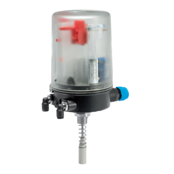
3.3 Function The GEMÜ 4241 combi switchbox indicates the current position of the valve. When the valve is opened, the spindle in the combi switchbox moves upwards and indicates that the valve is OPEN using the communication interface. When the valve is closed, the spring in the mounting kit presses the spindle in the combi switchbox downwards and indicates that the valve is CLOSED using the communication interface. -
Page 7: Gemü Conexo
4 GEMÜ CONEXO 4 GEMÜ CONEXO Order variant In the corresponding design with CONEXO, this product has an RFID chip (1) for electronic identification purposes. The posi- tion of the RFID chip can be seen below. The CONEXO pen helps read out information stored in the RFID chips. The CONEXO app or CONEXO portal is required to view this information. -
Page 8: Correct Use
Special conditions of use 1. The special conditions of the Ex components used must be observed. 2. The housing must be installed protected against mechanical influences. 3. Layers of dust > 5 mm must be avoided. GEMÜ 4241 8 / 27 www.gemu-group.com... -
Page 9: Order Data
9 Connection diagram NAMUR terminals OPEN/CLOSE 8 V NAMUR sensor; 24 V DC pilot valve 10 Travel sensor version Potentiometer, 75 mm length 11 Special version ATEX (2014/34/EU), IECEx 9 / 27 9 / 27 www.gemu-group.com www.gemu-group.com GEMÜ 4241 GEMÜ 4241... -
Page 10: Technical Data
7.5 Mechanical data Installation position: Optional Weight: 420 g Protection class: IP 65 acc. to EN 60529 IP 67 acc. to EN 60529, is reached with piped air outlet Stroke: 5 to 75 mm GEMÜ 4241 10 / 27 www.gemu-group.com... - Page 11 Ci = 30 nF 7.7.2 Pilot valve Pilot valve, code N1: Ui = 30 V Ii = 330 mA Li negligible Ci negligible Pilot valve, code N2: Ui = 30 V Li negligible Ci negligible www.gemu-group.com 11 / 27 GEMÜ 4241...
-
Page 12: Dimensions
2. Avoid UV rays and direct sunlight. 3. Do not exceed the maximum storage temperature (see chapter "Technical data"). 4. Do not store solvents, chemicals, acids, fuels or similar fluids in the same room as GEMÜ products and their spare parts. GEMÜ 4241 12 / 27 www.gemu-group.com... -
Page 13: Assembly And Installation
1. Lay cables and pipework so that no condensate or rain water that remains on the pipework / cables can enter the cable glands or plugs of the product. 2. Check that all cable glands or plugs are positioned correctly 3. Check the sealing ring 1 for any damage and correct positioning before tightening the cover. www.gemu-group.com 13 / 27 GEMÜ 4241... - Page 14 1 using the spring 2 and fix it in place using the operating bush 3. 3. Tighten the operating bush 3 by turning it 4. Affix the O-ring 5 and the adapter 6. clockwise. GEMÜ 4241 14 / 27 www.gemu-group.com...
- Page 15 NOTICE ▶ For some valves (e.g. GEMÜ 650 and GEMÜ 687) it is necessary to fit a pressure disc between the threaded adapter and the actuator head. This is included in the required mounting kits, sometimes with an additional O-ring (only GEMÜ 650 with normally open and double-acting control function –...
- Page 16 Operating bush Distance piece Spindle Actuator spindle Travel sensor 1) Only available for valves with the NO and DA control functions. 2) Only included in required mounting kits. The design depends on the valve. GEMÜ 4241 16 / 27 www.gemu-group.com...
- Page 17 4. Turn the housing clockwise to align the pneumatic or electrical connections. 5. Set the switch on the product. CAUTION Incorrect installation of the product. ▶ Damage to the housing. Only tighten the product using the spanner flats provided for this purpose. ● www.gemu-group.com 17 / 27 GEMÜ 4241...
- Page 18 11. Release red levers 5. ð Switch 4 engages. ð Switch 6 engages. ð The upper switching position is set. ð The lower switching position is set. 12. Make the electrical connection (see “Electrical connection“, page 20). GEMÜ 4241 18 / 27 www.gemu-group.com...
- Page 19 17. To check that everything is working correctly, open and close the valve and observe the signalling. 18. If the settings need to be readjusted, switch off power to the product again and repeat the steps in "Setting the switching positions". www.gemu-group.com 19 / 27 GEMÜ 4241...
-
Page 20: Pneumatic Connection
Do not disconnect the device until the power has been switched off or the area has been classified as non- ● hazardous. DANGER Danger of explosion ▶ Risk of severe injury or death. Danger from sparking. Never disconnect the connection cables when live. ● GEMÜ 4241 20 / 27 www.gemu-group.com... - Page 21 12. Only connect the product to intrinsically safe electric circuits that are approved with an EC type examination certificate and which do not exceed the maximum values of the respective sensors for Ui, Ii, Pi, Ci and Li. www.gemu-group.com 21 / 27 GEMÜ 4241...
- Page 22 12 V DC, control input 12.5 12 V DC pilot valve, ordering option Connection diagram, code P5 12.5.1 Connection diagram Signal name L+, CLOSED switch L-, CLOSED switch 12 V DC, control input GND, control input n. c. GEMÜ 4241 22 / 27 www.gemu-group.com...
-
Page 23: Manual Override
Use a flathead screwdriver (maximum slot width of 6 mm) to unscrew the manual override screw 3 anticlockwise as far as it will go. NOTICE ▶ Control air and the minimum pressure must be available to use the manual override. www.gemu-group.com 23 / 27 GEMÜ 4241... -
Page 24: Troubleshooting
7. Carry out inspection and servicing for products in the potentially explosive area to DIN EN 60079-17. 15.1 Spare parts No spare parts are available for this product. If it is faulty, please return it to GEMÜ for repair. 15.2 Cleaning the product... -
Page 25: Disassembly
Returned goods can be processed only when this note is completed. If no return delivery note is included with the product, GEMÜ cannot process credits or repair work but will dispose of the goods at the op- erator's expense. -
Page 26: Eu Declaration Of Conformity In Accordance With 2014/34/Eu (Atex)
19 EU Declaration of conformity in accordance with 2014/34/EU (ATEX) EU Declaration of Conformity in accordance with 2014/34/EU (ATEX) GEMÜ Gebr. Müller Apparatebau GmbH & Co. KG Fritz-Müller-Straße 6-8 74653 Ingelfingen-Criesbach, Germany declare that the product listed below complies with the requirements of directive 2014/34/EU for intended use in potentially explosive areas. - Page 27 GEMÜ Gebr. Müller Apparatebau GmbH & Co. KG Subject to alteration Fritz-Müller-Straße 6-8, 74653 Ingelfingen-Criesbach, *88611053* Germany 03.2020 | 88611053 Phone +49 (0)7940 123-0 · info@gemue.de www.gemu-group.com...